Impact of a Liquid Drop on a Granular Medium: inertia, viscosity and surface tension effects on the drop deformation
Abstract
An experimental study of liquid drop impacts on a granular medium is proposed. Four fluids were used to vary physical properties: pure distilled water, water with glycerol at concentrations and v/v and water with Tween at the concentration of g.l-1. The drop free fall height was varied to obtain a Weber number () between and . Results showed that obtained crater morphologies highly depend on the impacting drop kinetic energy (). Different behaviours during the drop spreading, receding and absorption are highlighted as function of the fluids viscosity and surface tension. Experimental absorption times are also commented and compared with a simplified theoretical model. Drops maximal extensions and craters diameters were found to scale as and respectively. In both cases, found dependencies are smaller than those reported in literature: for drop impacts on solid or granular surfaces and for spherical solid impacts on granular media.
1 Introduction
The phenomenon of droplet impact on non-cohesive granular media is present in various industrial processes as food engineering, candy coated pills fabrication, starch wetting…(Vaclavik and Christian, 2008). It is also of great importance in environmental sciences: water erosion of soil, pollution of rivers and lakes, rainfall simulations (van Dijk et al., 2002; Ries et al., 2009) …However, studies of this phenomenon are very scarce. (Holman et al., 2002) studied the micro-metric drop impact on micro-metric grains of same sizes. Besides, authors used a very particular fluid, an aqueous polymer solution in this case. Others studied drops imbibition into powder beds with no impact. The drops were deposited on the granular surface with no kinetic energy (Hapgood et al., 2002). Very recently, the problem has been investigated by (Katsuragi, 2010) where the author only focused on the granular medium deformation, in particular the resulting craters morphologies for different drops velocities and granular media (grains sized between and m). Moreover, he reported the existence of different craters types depending on the drop free fall height and that water drop maximal extensions , that he assumes equal to the crater diameter, scales as . However, (Nefzaoui and Skurtys, 2009) reported that, for water drops impact on coarser grains (average particle diameter m), and that the crater diameter is not equal to .
On the other side, the drop impact phenomenon onto thin liquid films or dry solid surfaces has been thoroughly studied for over a century (Yarin, 2006). The drop behaviour after collision with the surface is very complex since it depends on the physico-chemical characteristics of the drop and of the impact surface. The drop impact phenomenon can be divided in several sub-processes identified as spreading, receding, splashing and bouncing (Rioboo et al., 2002; Wal et al., 2006; Yarin, 2006). In recent years more attention has been shown to study the role of the surface roughness on the drop impact process (Kannan and Sivakumar, 2008; Xu, 2007). In particular, it has been shown that the splashing of impacting drops is promoted by increasing the mean surface roughness.
Spherical solid impact into granular media were investigated to some extent decades ago (Nelson et al., 2008; Caballero et al., 2007; Walsh et al., 2003; Zheng et al., 2004; Lohse et al., 2004). For impact energies ranged between and J, the morphology of the craters was reported in detail by (Walsh et al., 2003). In particular, the scaling of crater dimensions has been studied, and a power-law relationship between crater diameter and the energy of impact can be derived in certain limits: . The process of crater formation is complex since the resistance of the granular medium to the projectile penetration depends on the medium intrinsic properties, its packing mode and the applied force. Indeed, impacting sphere penetration dynamics and grain ejection have been shown to be very different whether the granular material is loose or dense (Lohse et al., 2004). Another type of experiments concerns a bead impact on a granular target made of similar beads (Beladjine et al., 2007).
In this paper, an experimental study of drop impacts on a granular medium (glass beads) is proposed. Four different liquids were used in order to study the effect of viscosity and surface tension on the drop deformation for different impact velocities and try to determine the relevant parameters that governs the phenomenon. Different behaviours are highlighted depending on the receding magnitude and occurrence of splashing. The impact dynamics are also described through the spreading drop diameter temporal evolution obtained by high speed video. Maximal spreading drop diameters are compared to the case of drop impacts on solid surfaces (Clanet et al., 2004; Rein, 1996). Crater morphologies obtained by varying the drop kinetic energy at impact over more than three orders of magnitude are also presented and discussed. A power law for craters diameters dependence on the drop kinetic energy at impact is proposed and compared to solid projectiles impacts on granular media results.
2 Material and methods
2.1 Fluids and drop generation
In our experiments, liquid drops were generated by a precision flat tipped syringe needle (Sigma-Aldrich, USA, St. Louis) connected to a digitally controlled syringe pump (Model 1000, New Era Pump System Inc., Farmingdale, NY, USA). Liquid flow rate was sufficiently low to get a nil drop initial velocity (0.05 ml.min-1). Four fluids were used: pure distilled water, water with glycerol at 2 concentrations 1:1 and 1:2 v/v and water with Tween at the concentration of g.l-1. Their physical properties were measured and are presented in Table 1. Three flat tipped needles (gauge , , ) were used to obtain various drop diameters , between and mm. Drops are assumed with some assurance to maintain a spherical shape through the free fall since their radius were lower than the capillary length defined by (Landau and Lifshitz, 1959). This was verified on the captured images for the biggest drops. Different impact velocities within the range of to m.s-1 were obtained changing the drop release height up to mm. For each impact, was measured from captured images. The kinetic energy of the drop at impact, given by was varied between and J. Surface energy of the free drop surface, was varied between and J.
2.2 Granular medium
Target surface was composed of a circular container which was mm in diameter and mm deep. The container was filled with glass beads (G8893, Sigma-Aldrich, USA, St. Louis) which had an effective average particle diameter m and a density about kg.m-3. Granular medium compaction had a great effect on the crater formation. It was thus important to have the same initial beads bed state in general, and compaction in particular, for each drop impact. For this purpose, the same protocol was respected for each sample preparation. Beads were gently rolled into the container using a glass funnel. The container was overfilled and the surface was levelled using a straight-edge. There is no doubt that this operation introduced local compaction non-homogeneities. Finally, samples were weighed and the same mass of beads was used for each. Packing fractions of about were deduced from the granular material measurements of the mass and volume of the bulk.
| Fluid | (kg.m-3) | (mPa.s) | (mJ.m-2) | (mm) | |
| Water | 996 | 1 | 72.2 | 2.88 - 3.25 - 3.65 | - |
| Water-glycerol 1:1 | 1121 | 6 | 66.9 | 3.47 | 11.8 |
| Water-glycerol 1:2 | 1162 | 19 | 65.1 | 3.39 | 37.5 |
| Water-tween (g.l-1) | 996 | 1 | 36 | 3 | 3 |
2.3 Fluid-granular contact angle
The contact angle of water over the granular media was measured through a capillary suction experiment as detailed by (Xue et al., 2006). The method consists in observing the velocity of a fluid rising in a granular column due to capillary forces. Taking into account hydrostatic, viscous and capillary effects (only inertial effects are not considered here) leads to the following relation between the contact angle and the other physical parameters and variables (Xue et al., 2006):
| (1) |
where , , and are the fluid surface tension, density, dynamic viscosity and the fluid-granular advancing contact angle respectively. Moreover, and are time and the rising fluid front position and is the fluid front velocity given by . The only unknown is and can easily be deduced from Eq. (1) since other parameters are measured experimentally.
2.4 Granular medium pore diameter
The granular medium mean pore diameter is needed to estimate the drop absorption times. According to (Xue et al., 2006), Washburn equation with hydrostatic effects leads to the following expression of the pore average radius :
| (2) |
This relation leads to consistent results when inertial effects are negligible, thus not at early times when and are too small.
2.5 Images acquisition
The impacting drop and the granular medium evolution, e.g. the drop spreading and receding, crater formation, were observed experimentally with a high-speed video Pulnix TM-6740GE (Pulnix, Inc., San Jose, CA , USA) with a pixel resolution of . It could capture frames per second (fps) in full frame and fps with a reduced matrix resolution. The camera was mounted on a boom stand which provided easy vertical or horizontal movement and stable support for the camera. A zoom video lens ( mm f/D, Edmund Optics, NJ, USA) was mounted on the video camera. Resulting frames were processed using ImageJ software (National Institutes of Health, USA).
3 Results and discussion
A mathematical formulation of the impact leads to consider the equation of continuity and the momentum equations both in the radial and in the axial directions. Three dimensionless numbers can be considered after the adimensionalization procedure: Reynolds (), Weber (), Froude (). In all tests, gravitational effect was negligible compared to inertia (). Thus, only the Weber number, which compares the inertial forces to surface tension and the Reynolds number (), ratio of inertial to viscous forces were retained as parameters of the problem. Thus, the dynamics at impact was driven by an interplay between the kinetic energy, viscosity and the droplet surface tension. The adimensional number can also be used to take simultaneously into account the three parameters () Fedorchenko et al. (2005). The three typical phases observed after the drop impact on the granular medium, i.e. the spreading, receding and absorption, are detailed in the next paragraphs.
3.1 Drop spreading dynamics
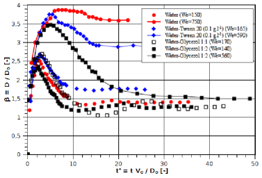
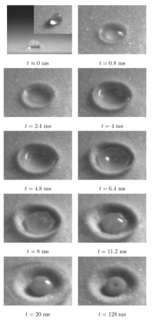
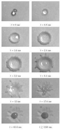
In Fig. 1, the temporal evolution of the spreading factor after impact is presented for high and low Weber numbers and different considered fluids. In a usual manner for inertia governed impacts, time is made nondimensional using the impact velocity and the initial spherical drop diameter . In all cases, three phases can be observed: drop spreading (), receding () and absorption. Spreading was the first stage of drop deformation after impact. The droplet initially flattens and spreads out horizontally into a pancake shape. Even if the description of the drop deformation before ms was beyond our experimental capacities, it is tantalizing to say that in the first instants, the drop was not deformed and just penetrates into the granular medium like a spherical ball for early times as shown in Fig. 3 (for ). Indeed, in almost all first impact pictures, non-deformed spherical drops partially penetrating the granular medium were observed. This is not the case for a drop impacting on a solid surface where the drop deformation starts at impact time and its diameter evolution scales as (Rioboo et al., 2002).
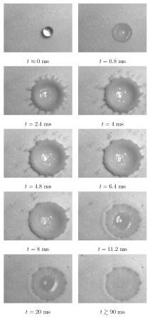
Receding was the second stage of drop deformation after impact (see Fig. 1). In the case of water and Tween drops, the receding behaviour was considerably different at intermediate (and at low all the more) and high . For , a "total receding" was observed, the drop final spreading factor is relatively small: (water) and (tween). Besides, when it reaches its final diameter, the fluid recovers a drop-like shape (see Fig. 3). Actually, at low and intermediate , the drop spherical shape recovery let think that receding was governed by capillary forces. Whilst for higher kinetic energy, (water) and (tween), final drop spreading factor was closer to : (water) and (tween). In contrast with the previous situation, we can talk about "partial receding" (see Fig. 4, for ms). In this case, the kinetic energy of the spreading fluid dominated the drop surface energy therefore the fluid groups into fingers along the outer rim of the droplet which had sufficient energy to overcome the surface tension and pinch off into smaller droplets. It is interesting to notice that a lower surface tension permits to increases surface area and hence . In fact, for an impact at , a Tween drop reached the same maximal extension than a water drop impacting at around higher () (see Fig. 1). On the other hand, for highly viscous fluids (water-glycerol mixtures) with a surface tension close to water, the impacting drop receded to . Unlike water and Tween drops, no significative difference on the final drop diameter (after receding) was observed between high and low impacts (see Fig. 1). However, increases with . Besides, oscillations of the spreading drop diameter were observed for low .
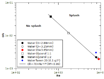
For the different considered fluids, splashing occurs at very high kinetic energy. To delineate the boundary between splashing and non-splashing regions a power-law relation based on and numbers can be established: where is a real coefficient. Figure 2 shows and values corresponding to the appearance of splashing. The boundary between splash-no splash then follows the relation: . This correlation can be compared with those reported by (Kannan and Sivakumar, 2008) for a drop impinging upon a dry solid surface or upon a thin fluid film where , respectively. As , both exponents can be compared. To splash, the same drop impacting on a granular medium needs higher kinetic energy than those impacting upon a thin fluid film since .
3.2 Maximum drop deformation
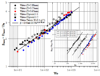
In Fig. 6, the maximal spreading factor of drops impacting with different kinetic energies, is plotted versus . All data were found to collapse in a power law: in spite of the surface tension and viscosity differences. A law of the type leads to since . Our results do not concord with the models describing the drop impact on a solid surface reported by (Clanet et al., 2004) and (Rein, 1996), and , respectively. Recently, (Katsuragi, 2010) reported that after the impact of a free-falling water drop onto a granular layer (where the grain size is varied between and m), scales as . In the case of a unique drop and even for drops of different diameters among values considered in this work (), we can write . The insert of Fig. 6 confirms our relation between the maximum spreading factor and the Reynolds number for the four fluids with a high coefficient of determination ().
3.3 Drop absorption
Figures 3 and 4 show time sequences of a mm and mm diameter water drop impact for and , respectively. Absorption is considered to be achieved when no visible difference between two and more consecutive frames can be observed. An absorption time of ms was obtained in the first case and ms in the second. It was surprising at first sight to find that the biggest drop took less time to be absorbed (an average bulk flow almost three times higher). After observing thoroughly the detailed frames sequences (which can not be shown here due to the high frames number), it has been found out that the mechanisms were not the same in the two cases. In the first case in particular, and for all impacts at in general, the majority of drop absorption takes place after the drop spreading and receding and while the fluid is at rest. A fluid in a drop-like shape is then absorbed. Absorption and receding are quite independent and the latter is governed by capillary forces. In the second case, absorption is observed to start relatively early and before the drop starts receding. This was observed for almost all impacts at where a flat film is absorbed instead of a spherical drop. In fact, the higher the impact kinetic energy, the bigger the drop maximal extension and the thinner the spreading film. Besides, the fluid film absorption does not start at the periphery, where the film thickness may be thought to be the lowest. Actually, the fluid film thickness decreases from the center to periphery at first spreading stages (Clanet et al., 2004)(Roisman et al., 2002). However, when the spreading lamella reaches its maximal extension, a blob appears at the rim. While there is no global fluid motion ( in Fig. 1), a local flow from the center to the periphery still exists, feeding the blob and thinning the fluid film at its center (Roisman et al., 2002). Fluid central sucking induces lamella receding. Therefore absorption is not the last stage of drop deformation. Absorption and receding are tightly coupled and we talk about an absorption induced receding.
Table 2 reports measured absorption times for different fluids and for different release heights. A few interesting remarks can be made.
First, these figures confirm that absorption times are systematically (except for very viscous fluids) higher for low release heights as explained above. Second, this difference of absorption times for different release heights decreases when the fluid viscosity increases. Finally, it vanishes for very viscous fluids (Fig. 5). In fact, for glycerol-water 1:2 (19 times more viscous than water and water-tween mixture), no difference in absorption times is observed for different release heights while it can vary from one to 5 for water or water-tween mixture.
| Fluid | D(mm) | We | (s) | (s) |
|---|---|---|---|---|
| Water | 2.88 | 150 | 0.12 | 0.128 |
| Water | 3.65 | 750 | 0.09 | 0.09 |
| Water-tween | 3 | 164 | 0.27 | 1.25 |
| Water-tween | 3 | 549 | 0.05 | 1.25 |
| Water-Glycerol 1:1 | 3.47 | 114 | 1.68 | 6.3 |
| Water-Glycerol 1:1 | 3.47 | 570 | 1.06 | 6.3 |
| Water-Glycerol 1:2 | 3.39 | 119 | 2.29 | 14.1 |
| Water-Glycerol 1:2 | 3.39 | 546 | 2.43 | 14.1 |
It can be interesting to calculate theoretically absorption times and to compare them with the experimental results. The method presented and confirmed in some particular cases by (Hapgood et al., 2002) was adopted. In (Hapgood et al., 2002) experiments, the drop was deposited with a syringe on the surface of the granular medium with no kinetic energy. With this method, the drop absorption was assumed to take place over a constant drop-granular medium contact surface (constant drawing area). Absorption time is then given by:
| (3) |
where is the initial drop volume, is the porous medium porosity, is the pore radius, , and are the fluid surface tension, viscosity and the fluid-granular medium contact angle respectively.
In our case, calculated times corresponded to experimental times in very few cases (See Table 2), for water drops falling from very low heights for example (experimental conditions very close to those of Hapgood) and no concluding results were obtained for water-tween and water-glycerol mixtures. The calculated times depended very highly on contact angles which were quite difficult to determine with a good precision. Besides, using this model implies the implicit assumption that no absorption occurs during spreading and receding which is obviously not true.
3.4 Crater morphologies
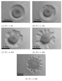
In Figure 7, for different Weber numbers, examples of crater morphologies observed by impacting into a container of glass beads a mm diameter water drop are shown. The granular medium keeps a memory of the fluid shape at its maximal extension, thanks to its deformability and wettability. Similar craters were also observed with the different fluids. At low , e.g. (Fig. 7-A), a crater with in its centre a circular agglomeration of glass beads was formed. A rotationally symmetric rim was raised above the original target surface level. Glass beads driven by the receding drop formed a central agglomeration where the surface energy is sufficiently strong to join glass beads by capillary cohesion forces. This crater morphology was observed for . As was increased the first irregularities appeared inside the crater and the agglomeration in the centre was less circular (Fig. 7-B). These irregularities became more marked at higher (Fig. 7-C-D). They can be associated with the fingering instability at the rim of the expanding water drop like reported in the previous studies of the water drop on a solid surface (Allen, 1975; Mehdizadeh et al., 2004). This crater morphology occurred in the range . This kind of crater was not reported by (Katsuragi, 2010). In its work, finer grains were used and lower numbers were considered which may explain these differences. At higher kinetic energy, a layer of wet glass beads appears instead of the central agglomeration previously described (Fig. 7-E). It is due to the water drops splashing.
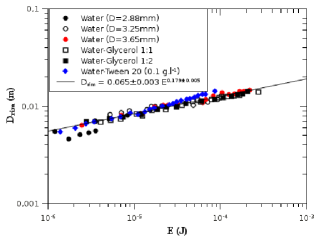
In Figure 8, the crater rim diameter , measured at the top of the crater rim, is plotted against kinetic energy of drops at impact. As expected, for different drop diameters and fluids, the measured diameter increased with increasing . Moreover, the data are well described by a power law over more than three orders of magnitude in . However, this law is slightly different of those reported for the impact of a solid projectile where scales as (Walsh et al., 2003; Uehara et al., 2003) and the water drop impact reported by (Katsuragi, 2010).
4 Conclusion
An experimental study of liquid drop impacts on a granular medium has been presented for Weber numbers () in the range . Four liquids were used to vary either the viscosity (between and mPa.s) or the surface tension (between and mJ.m-2). Different crater morphologies have been observed depending on the Weber number. The crater rim diameter was found to scale as a power-law of the kinetic energy of drops at impact . This law was slightly different of those reported for the impact of a solid projectile where scales as .
The temporal evolution of the spreading factor () was presented. The effects of viscosity, surface tension and inertia on the spreading, receding and absorption were commented. A power-law smaller than those recently reported by Katsuragi (2010) has been deduced for the different fluids.
The boundary between splash-no splash was found to follow the relation: . In particular, to splash, the same drop impacting on a granular medium needs higher kinetic energy than those impacting upon a thin fluid film.
Measured absorption times depended highly on and the fluid viscosity. Calculated times according to the simplified model reported by Hapgood et al. (2002) were not in agreement with experiments. A better prediction of absorption times must be achieved taking into account absorption during spreading and receding.
Finally, more imagery acquisition is necessary to understand the fluid granular interactions (crater formation mechanisms) and to develop an energetic model that details the initial drop kinetic energy dissipation during the drop deformation (viscous dissipation, …) and crater formation (granular dissipation).
Acknowledgements
The authors thank F. Melo for discussions and help, the CONICYT sponsor of the Bicentenario Grant (PBCT PSD-) and Dicyt (project ).
References
- Allen [1975] R.F. Allen. The role of surface tension in splashing. J. Colloid Interface Sci., 51:350, 1975.
- Beladjine et al. [2007] D. Beladjine, M. Amni, A. Valance, and L. Oger. Collision process between an incident bead and a three-dimensional granular packing. Phys. Rev. E, 75:061305, 2007.
- Caballero et al. [2007] G. Caballero, R. Bergmann, D. Van der Meer, A. Prosperetti, and D. Lohse. Role of air in granular jet formation. Phys. Rev. Lett., 99:018001, 2007.
- Clanet et al. [2004] C. Clanet, C. Beguin, D. Richard, and D. Quere. Maximal deformation of an impacting drop. J. Fluid Mech., 517:199, 2004.
- Fedorchenko et al. [2005] A. I. Fedorchenko, A.B. Wang, and Y.H. Wang. Effect of capillary and viscous forces on spreading of a liquid drop impinging on a solid surface. Phys. Fluids, 17(9):093104, 2005.
- Hapgood et al. [2002] K.P. Hapgood, J.D. Litster, S.R. Biggs, and T. Howes. Drop penetration into porous powder beds. J. Colloid Interface Sci., 253(2):353, 2002.
- Holman et al. [2002] K.R. Holman, M.J. Cima, S.A. Uhland, and E. Sachs. Spreading and infiltration of inkjet-printed polymer solution droplets on a porous substrate. J. Colloid Interface Sci., 249(2):432, 2002.
- Kannan and Sivakumar [2008] R. Kannan and D. Sivakumar. Impact of liquid drops on a rough surface comprising microgrooves. Exp. Fluids, 44:927, 2008.
- Katsuragi [2010] H. Katsuragi. Morphology scaling of drop impact onto a granular layer. Phys. Rev. Lett., 104:218001, 2010.
- Landau and Lifshitz [1959] L.D. Landau and E.M. Lifshitz. Fluid Mechanics, Course of Theoretical Physics Vol. 6. Addison-Wesley, Reading, 1959.
- Lohse et al. [2004] D. Lohse, R. Bergmann, R. Mikkelsen, C. Zeilstra, D. Van der Meer, M. Versluis, K. Van der Weele, M. Van der Hoef, and H. kuipers kuipers. Impact on soft sand: Void collapse and jet formation. Phys. Rev. Lett., 93:198003, 2004.
- Mehdizadeh et al. [2004] N.Z. Mehdizadeh, S. Chandra, and J. Mostaghimi. Formation of fingers around the edges of a drop hitting a metal plate with high velocity. J. Fluid Mech., 510:353, 2004.
- Nefzaoui and Skurtys [2009] E. Nefzaoui and O. Skurtys. Water drop impact on granular medium. In Book of Abstracts. Southern Workshop on Granular Materials - SWGM09, Nov. 30 to Dec.s 4, 2009 - Viña del Mar, Chile, 2009.
- Nelson et al. [2008] E.L. Nelson, H. Katsuragi, P. Mayor, and D.J. Durian. Projectile interactions in granular impact cratering. Phys. Rev. Lett., 101:068001, 2008.
- Rein [1996] M. Rein. The transitional regime between coalescing and splashing drops. J. Fluid Mech., 306:145, 1996.
- Ries et al. [2009] J.B. Ries, M. Seeger, T. Iserloh, S. Wistorf, and W. Fister. Calibration of simulated rainfall characteristics for the study of soil erosion on agricultural land. Soil and Tillage Research, 106(1):109, 2009.
- Rioboo et al. [2002] R. Rioboo, M. Marengo, and C. Tropea. Time evolution of liquid drop impact onto solid, dry surfaces. Exp. Fluids, 33:112, 2002.
- Roisman et al. [2002] Ilia V. Roisman, Romain Rioboo, and Cameron Tropea. Normal impact of a liquid drop on a dry surface: model for spreading and receding. Proc. R. Soc. London, Ser. A, 458(2022):1411, 2002.
- Uehara et al. [2003] J.S. Uehara, M.A. Ambroso, R.P. Ojha, and D.R. Durian. Low-speed impact craters in loose granular media. Phys. Rev. Lett., 90:194301, 2003.
- Vaclavik and Christian [2008] V.A. Vaclavik and E.W. Christian. Essentials of Food Science. Springer, third edition, 2008.
- van Dijk et al. [2002] A. I. J. M. van Dijk, L. A. Bruijnzeel, and C. J. Rosewell. Rainfall intensity-kinetic energy relationships: a critical literature appraisal. J. Hydrol. (Amsterdam, Neth.), 261(1-4):1, 2002.
- Wal et al. [2006] R.L. Vander Wal, G.M. Berger, and S.D. Mozes. The splash / non-splash boundary upon a dry surface and thin fluid film. Exp. Fluids, 40:53, 2006.
- Walsh et al. [2003] A.M. Walsh, K.E. Holloway, P. Habdas, and J.R. de Bruyn. Morphology and scaling of impact craters in granular media. Phys. Rev. Lett., 91:104301, 2003.
- Xu [2007] L. Xu. Liquid drop splashing on smooth, rough, and textured surfaces. Phys. Rev. E, 75:056316, 2007.
- Xue et al. [2006] H.T. Xue, Z.N. Fang, Y. Yang, J.P. Huang, and L.W. Zhou. Contact angle determined by spontaneous dynamic capillary rises with hydrostatic effects: Experiment and theory. Chem. Phys. Lett., 432:326, 2006.
- Yarin [2006] A.L. Yarin. Drop impact dynamics: Splashing, spreading, receding, bouncing …. Annu. Rev. Fluid Mech., 38:159, 2006.
- Zheng et al. [2004] X.J. Zheng, Z.T. Wang, and Z.G. Qiu. Impact craters in loose granular media. Eur. Phys. J. E: Soft Matter Biol. Phys., 13:321, 2004.