Measurement of the fractional quantum Hall energy gap in suspended graphene
Abstract
We report on magnetotransport measurements of multi-terminal suspended graphene devices. Fully developed integer quantum Hall states appear in magnetic fields as low as 2 T. At higher fields the formation of longitudinal resistance minima and transverse resistance plateaus are seen corresponding to fractional quantum Hall states, most strongly for . By measuring the temperature dependence of these resistance minima, the energy gap for the 1/3 fractional state in graphene is determined to be at 20 K at 14 T.
pacs:
73.63.-b, 73.22.-f, 73.43.-fIn the low magnetic field regime, the integer quantum Hall (IQH) effect of graphene is marked by an anomalous half-integer quantum Hall conductivity , where is an integer and is the Landau level (LL) degeneracy resulting from the degenerate spin and valley isospin degrees of freedom. This anomalous quantum Hall conductivity led to the observation of the filling factor sequence novo2 ; zhang1 . Subsequently, new broken-symmetry IQH states, corresponding to filling factors have been resolved in magnetic fields of 20 T, indicating the lifting of the fourfold degeneracy of the LLs zhang2 ; zhang3 . These filling factors have been suggested to be the result of various novel correlated states mediated by electron-electron (e-e) interactions eeReviews .
In the strong quantum limit, e-e interactions in 2-dimensional electron gasses (2DEGs) can lead to the fractional quantum Hall (FQH) effect tsu , many-body correlated states where the Hall conductance quantization appears at fractional filling factors. In recent investigations of transport properties in two-terminal high-mobility suspended graphene devices kiril3 ; du2 , a quantized conductance corresponding to the FQH state has been observed, suggesting the presence of strong e-e interactions in this system. However, due to the inherent mixing between longitudinal and transverse resistivities in this two-terminal measurement ab , quantitative characterization of the observed FQH states such as the FQH energy gap is only possible in an indirect way ab2 . Although multi-terminal measurements on suspended graphene samples have been reported previously kiril1 ; du1 , the mechanical gu or thermal instability ska of these samples has precluded even the observation of a fully-quantized IQH effect.
Recently, the improvement of graphene mobility up to 8 m2/Vsec has been reported for substrate-supported graphene devices fabricated on a single-crystal hexagonal boron nitride substrates Cory . Multi-terminal transport measurements performed on such devices in magnetic fields up to 35 T reveal several FQH states whose filling factors are mostly integer multiples of . The energy gaps of these states have been measured for , exhibiting an unusual hierarchy among these FQH states cory2 . However, the characterization of FQH states with , notably the FQH state, could not be reliably conducted in these samples due to inhomogeneous broadening near the charge neutrality point. As stronger e-e correlations are expected for this lower density regime, further experiments on cleaner samples are desirable.
In this letter, we report on the measurement of multi-terminal IQH and FQH effects in ultraclean suspended graphene samples in this low density regime. Filling factors corresponding to fully developed IQH states, including the broken-symmetry states and the FQH state are observed. The energy gap of the 1/3 FQH, measured by its temperature-dependent activation, is found to be much larger than the corresponding state found in the 2DEGs of high-quality GaAs heterostructures.
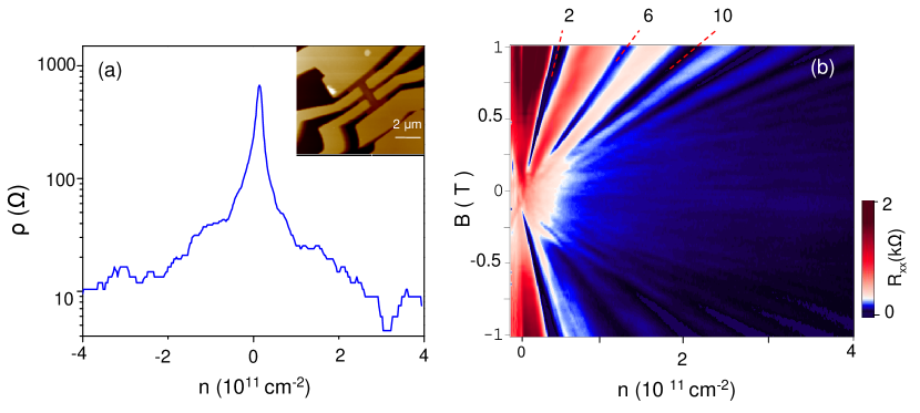
Our suspended graphene devices are fabricated using the method described in references kiril3 ; kiril1 : Mechanically exfoliated graphene samples are deposited on SiO2/Si substrates. Electrical contacts are made using electron-beam lithography followed by the thermal evaporation of Cr/Au electrodes. The SiO2 under the flake is subsequently removed via a chemical etch in buffered hydrofluoric acid. A typical multi-terminal graphene device with a lateral size 3 m, suspended 150-200 nm above the SiO2/Si substrate, is shown in the inset of Fig. 1(a).
We studied a total of three 4-terminal and one 6-terminal devices where better quality results were obtained in three of the samples, labeled S1, S2 and S3. The longitudinal resistance and transverse Hall resistance were measured as a function of the applied gate voltage on the doped Si back-gate, which tunes the carrier density in the graphene. The carrier density is determined using Hall measurements and , where is the applied magnetic field. The gate voltage is limited to less than 10 V to avoid electrostatic collapse of the suspended devices. The initial mobility of as-fabricated devices is typically less than 1.5 m2/Vs, comparable to samples on substrate. Sending a large current density (0.5 mA/m) through a device heats up the graphene samples up to C Berciaud , which typically removes many of adsorbed impurities, resulting in an extremely sharp peak in resistivity as changes from electrons to holes (Fig. 1(a)). In our study, the samples exhibit mobilities ranging from 8-15 m2/Vs at the temperature 1.7 K, where most of our data was taken. In these ultraclean suspended samples, the Shubnikov de Haas (SdH) oscillations, resulting from the quantized cyclotron orbits are observable at relatively low magnetic fields. Fig. 1(b) displays a Landau fan diagram where is plotted as a function of and in the low magnetic field regime ( 1 T). In this diagram the SdH oscillation minima (later developing to the quantum Hall minima) appear as strips fanning out from the origin point , with the slope . These strips survive in fields down to 0.1 T in our samples, in accordance with the mobility of 10 m2/Vs calculated from conductivity measurements.
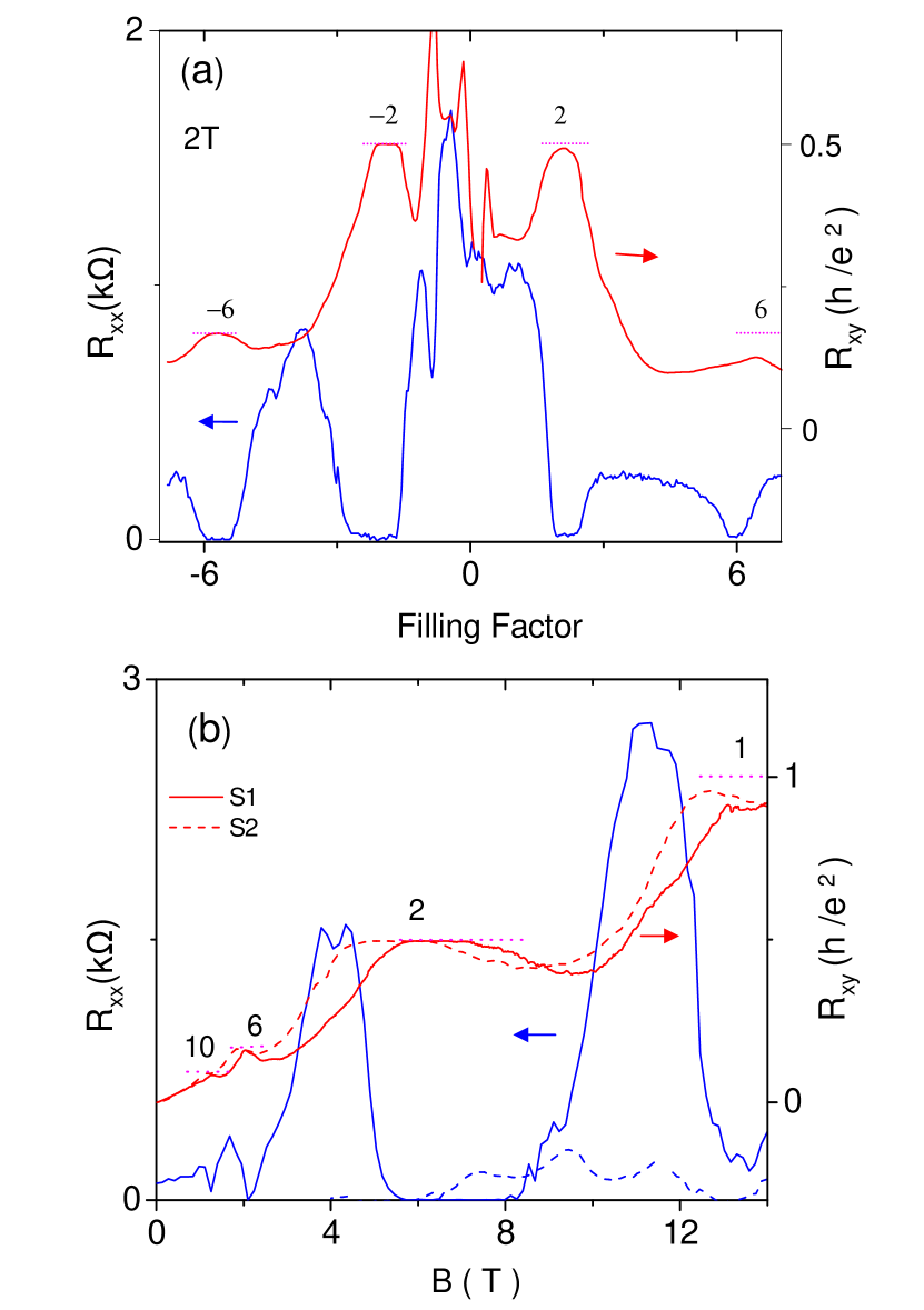
As increases, the observed SdH oscillations fully develop into the IQH effect. Fig. 2(a) shows and of device S1 as a function of filling factor (tuned by ) at a fixed magnetic field 2 T. A series of quantum Hall states, i.e., zeroes in and plateaus in , quantized to values with integer filling factors , are observed within the gate bias window. More IQH statescan be observed using a field sweep at fixed gate voltage. Fig. 2(b) shows and measured as a function of magnetic field at a fixed hole density of cm-2 for S1 and S2. At least two well-defined plateaus with values and are observed, while the broken-symmetry IQH state is being reached at 14 T. We note that the development of this Hall plateau is not complete, measuring only 95 % of the full quantization value. This deviation of the Hall resistivity from the expected quantization value may be attributable to the presence of non-ideal disordered contacts which can introduce a non-equilibrium population of edge states that perturbs the quantization for the small samples used here but . It has also been suggested that the proximity between the current leads and the voltage probes could short-circuit the hall voltage in such small samples ska .
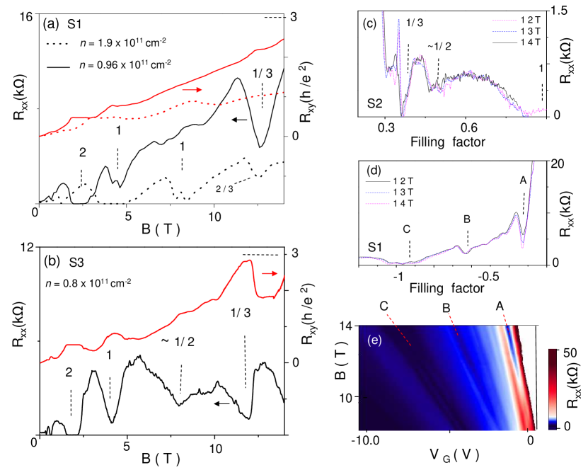
As we move to the low-density regime corresponding to , the FQH effect starts to be detected for 10 T in all three samples (S1, S2 and S3). Fig. 3(a) displays and plotted as a function of at a fixed density of 1011 cm-2 (dotted line) and 1011 cm-2 (solid line) respectively. At higher density, we notice that increases further and shows an additional dip at the field corresponding to . Upon further decreasing the density, lower filling fractions come into the observable window set by the maximum probing magnetic field (14 T), and develops even deeper local minimum at the field corresponding to with a plateau-like feature in . However, similar to the broken-symmetry IQH state, the corresponding features in are not fully quantized in this low density and high Hall voltage regime. In sample S3 (Fig. 3(b)), in addition to minimum around , another minimum is visible around , but there is no feature close to a 2/3 filling fraction.
We note that, when scaled by the filling factor, these local minima of are robust features at different magnetic fields and densities. Fig. 3(c) and Fig. 3(d) show the of S1 and S2 as a function of filling fraction at different and . The traces exhibit local minima corresponding to filling fractions 1/3, 1/2, 2/3 and 1. For all three samples, we observe strong minimum for 1 and 1/3. But 1/2 only shows up clearly for two samples S2 and S3 while 2/3 emerges only in S1, indicating that these features are rather fragile and are more sample dependent compared to 1/3. For example, in Fig. 3(d), in addition to the IQH state at (feature C) two other notable features emerge as relatively deep minima in (A and B), located at filling factors and respectively. Further confirmation on the nature of these states can be provided by means of a Landau fan diagram where is plotted as a function of and (Fig. 3(e)). From the slopes of the lines in marked A and B we estimate that features A and B follow and lines, respectively. We thus assign features A and B to be the minima corresponding to the 1/3 and 2/3 FQH states.
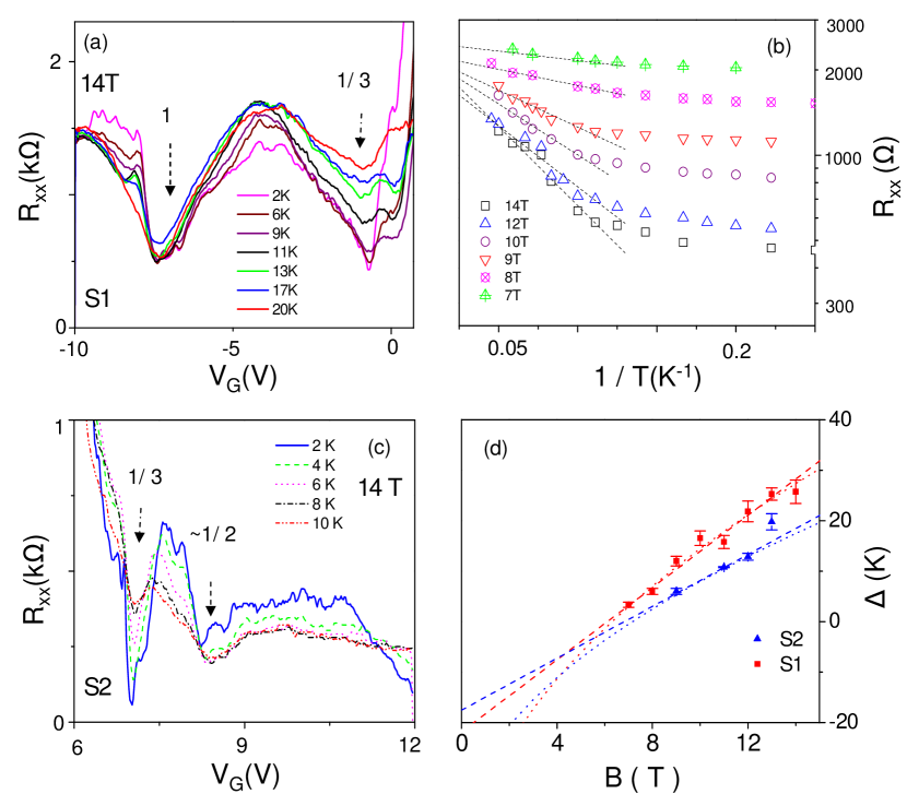
The strongly developed minima in for the 1/3 state now allows us to probe the energy gap associated with it. To quantify the energy of this FQH state, we measure the temperature dependence of . Fig. 4(a) and (c) display measured at a sequence of different temperatures at 14 T for S1 and S2, respectively. The minimum corresponding to the 1/3 FQH state, , increases as increases. An Arrhenius plot for the (Fig. 4(b)) shows an activation behavior indicated by in the temperature range between 9-22 K for S1. At lower temperatures (2-8 K) deviates from a simple activation behavior , turning into the slower temperature dependence expected for variable-range hopping behavior. Similar trends were observed in early experiments on GaAs 2DEGs boe .
From the high-temperature activation behavior, the transport gap of the 1/3 FQH state can be obtained using at a fixed magnetic field. Fig. 4(d) shows as a function of determined from the line fits in Fig. 4(b) for sample S1. A similarly determined activation energy gap for the 1/3 FQH state of sample S2 is also included in this figure (For this sample the shows an activation behavior in the temperature range between 4-13 K). For both samples, we obtained similar magnitude of the energy gap, increasing with increasing , as is expected.
Naively, the magnetic field dependence of energy gap of 1/3 FQH state would be expected to increase with , considering the e-e interaction energy scales with the Coulomb energy scale , where is the dielectric constant and is the magnetic length proportional to . As an alternative scenario, however, the activation energy gap could be linear in , if the nature of charged quasiparticle excitations of this FQH state are associated with spin-flips in skyrmion-like excitations of a spin-polarized FQH ground state deth . Given the field range and error bars of the data points, we cannot rule out either scenario at present. We remark the linear fit (dashed lines) yields a negative y-intercept 20 K, which can be interpreted as the broadening of the fractional state.This value is slightly larger than 4 K, the expected LL broadening estimated from the scattering time obtained from the mobility of the sample. However, the -fit (dotted lines) yields a negative y-intercept 60 K too large to be considered a reasonable .
Considering the LL broadening 20 K obtained from the linear fit, the intrinsic energy gap for 1/3 is estimated to be 40-45 K at 14 T. It has been predicted that the 1/3 state is both spin and valley-isospin polarized in the SU(4) configuration space apal , and calculations for this fully polarized 1/3 state have given a gap value of , with the numerical constant 0.05-0.1 apal ; toke1 . For graphene in vacuum, the dielectric constant from in-plane dynamic screening is estimated to be 5.24 gon . The predicted gap is then in the range 26-50 K at 14 T, in reasonable agreement with the gap measured in our experiment. For comparison, the observed disorder reduced in graphene is at least 3 times larger than that of the 2DEGs in the best quality GaAs heterojunctions in a similar field range deth . We further remark that obtained in this experiment is much larger than the gaps obtained for FQH states associated to considering those gaps are obtained at 35 T cory2 . This comparison thus suggests an unusual robustness of the 1/3 state in graphene, inviting further investigation to elucidate its microscopic nature Goerbig .
In conclusion, we have measured the quantum Hall effect in multi-terminal suspended graphene devices. Both the broken symmetry IQH and 1/3 FQH states emerge, as manifested by minima in and nearly quantized plateaus in . From activation behavior of the minima, the energy gap associated with the 1/3 FQH state is measured.
We thank J. K. Jain for helpful discussions. This work is supported by the DOE (DE-FG02-05ER46215).
∗ Present address: Department of Physics, Vanderbilt University, Nashville TN 37212.
References
- (1) K. S. Novoselov et al., Nature 438, 197 (2005).
- (2) Y. B. Zhang et al., Nature 438, 201 (2005).
- (3) Y. Zhang et al., Phys. Rev. Lett. 96, 136806 (2006).
- (4) Z. Jiang et al., Phys. Rev. Lett. 99, 106802 (2007).
- (5) Some reviews of recent theoretical work can be found in K. Yang, Solid State Commun. 143, 27 (2007) or; M. O. Goergig, arXiv:1004.3396
- (6) D. C. Tsui, H. L. Stormer, and A. C. Gossard, Phys. Rev. Lett.48, 1559 (1982).
- (7) X. Du et al., Nature 462, 192 (2009).
- (8) K. I. Bolotin et al., Nature 462, 196 (2009).
- (9) D. A. Abanin and L. S. Levitov, Phys. Rev. B 78, 035416(2008).
- (10) D.A. Abanin et al., Physical Review B, 81, 115410 (2010).
- (11) K. I. Bolotin et al., Solid State Commun. 146, 351 (2008).
- (12) X. Du at al., Nature Nano. 3, 491 (2008)
- (13) E. Prada et al., Phys. Rev. B 81, 161402(R) (2010); M. M. Fogler, A. H. Castro Neto, and F. Guinea, Phys. Rev. B 81, 161408(R) (2010).
- (14) I. Skachko et al., arXiv:0910.2518.
- (15) C.R.Dean et al., Nature Nanotechnology 5, 722 (2010).
- (16) C.R. Dean et al., arXiv:1010.1179.
- (17) S. Berciaud et al., Phys. Rev. Lett., 104, 227401 (2010)
- (18) M.Buttiker, Phys. Rev. B 38, 9375-9389 (1988).
- (19) G.S.Boebinger et al., Phys. Rev. Lett. 55, 1606 (1985).
- (20) A. F. Dethlefsen et al., Phys. Rev. B 74, 165325 (2006).
- (21) V. M. Apalkov and T. Chakraborty, Phys. Rev. Lett. 97, 126801(2006).
- (22) C. Toke et al., Phys. Rev.B 74, 235417 (2006).
- (23) J. Gonzalez, F. Guinea, and M. A. H. Vozmediano, Phys. Rev. B 59, R2474 (1999).
- (24) M. O. Goerbig, arXiv:1004.3396.