A unified first-principles study of Gilbert damping, spin-flip diffusion and resistivity in transition metal alloys
Abstract
Using a formulation of first-principles scattering theory that includes disorder and spin-orbit coupling on an equal footing, we calculate the resistivity , spin flip diffusion length and the Gilbert damping parameter for Ni1-xFex substitutional alloys as a function of . For the technologically important Ni80Fe20 alloy, permalloy, we calculate values of Ohm-cm, nm, and compared to experimental low-temperature values in the range Ohm-cm for , nm for , and for indicating that the theoretical formalism captures the most important contributions to these parameters.
pacs:
72.25.Rb, 71.70.Ej, 72.25.Ba, 75.40.Gb, 76.60.EsIntroduction.
The drive to increase the density and speed of magnetic forms of data storage has focussed attention on how magnetization changes in response to external fields and currents, on shorter length- and time-scales [Seethecollectionofarticles]UMS. The dynamics of a magnetization in an effective magnetic field is commonly described using the phenomenological Landau-Lifshitz-Gilbert equation
| (1) |
where is the saturation magnetization, is the Gilbert damping parameter (that is in general a tensor) and the gyromagnetic ratio is expressed in terms of the Bohr magneton and the Landé factor, which is approximately 2 for itinerant ferromagnets. The time decay of a magnetization precession is frequently expressed in terms of the dimensionless parameter given by the diagonal element of for an isotropic medium. If a non-equilibrium magnetization is generated in a disordered metal (for example by injecting a current through an interface), its spatial decay is described by the diffusion equation
| (2) |
in terms of the spin accumulation , the difference between the spin-dependent electrochemical potentials for up and down spins, and the spin-flip diffusion length van Son et al. (1987); *vanSon:prl88; Valet and Fert (1993). In spite of the great importance of and , our understanding of the factors that contribute to their numerical values is at best sketchy. For clean ferromagnetic metals Gilmore et al. (2007); *Gilmore:jap08; *Kambersky:prb07 and ordered alloys Liu et al. (2009) however, recent progress has been made in calculating the Gilbert damping using the Torque Correlation Model (TCM) Kamberský (1976) and the relaxation time approximation in the framework of the Boltzmann equation. Estimating the relaxation time for particular materials and scattering mechanisms is in general a non-trivial task and application of the TCM to non-periodic systems entails many additional complications and has not yet been demonstrated. Thus, the theoretical study of Gilbert damping or spin-flip scattering in disordered alloys and their calculation for particular materials with intrinsic disorder remain open questions.
Method.
In this paper we calculate the resistivity , spin-flip diffusion length and Gilbert damping parameter for substitutional Ni1-xFex alloys within a single first-principles framework. To do so, we have extended a scattering formalism Xia et al. (2001); *Xia:prb06 based upon the local spin density approximation (LSDA) of density functional theory (DFT) so that spin-orbit coupling (SOC) and chemical disorder are included on an equal footing. Relativistic effects are included by using the Pauli Hamiltonian.
For a disordered region of ferromagnetic (F) alloy sandwiched between leads of non-magnetic (N) material, the scattering matrix relates incoming and outgoing states in terms of reflection () and transmission matrices () at the Fermi energy. To calculate the scattering matrix, we use a “wave-function matching” (WFM) scheme Xia et al. (2001); *Xia:prb06 implemented with a minimal basis of tight-binding linearized muffin-tin orbitals (TB-LMTOs) Andersen et al. (1986); *Andersen:prb75. Atomic-sphere-approximation (ASA) potentials Andersen et al. (1986); *Andersen:prb75 are calculated self-consistently using a surface Green’s function (SGF) method also implemented Turek et al. (1997) with TB-LMTOs. Charge and spin densities for binary alloy and sites are calculated using the coherent potential approximation (CPA) Soven (1967) generalized to layer structures Turek et al. (1997). For the transmission matrix calculation, the resulting spherical potentials are assigned randomly to sites in large lateral supercells (SC) subject to maintenance of the appropriate concentration of the alloy Xia et al. (2001); *Xia:prb06. Solving the transport problem using lateral supercells makes it possible to go beyond effective medium approximations such as the CPA. Because we are interested in the properties of bulk alloys, the leads can be chosen for convenience and we use Cu leads with a single scattering state for each value of crystal momentum, . The alloy lattice constants are determined using Vegard’s law and the lattice constants of the leads are made to match. Though NiFe is fcc only for the concentration range , we use the fcc structure for all values of .
For the self-consistent SGF calculations (without SOC), the two-dimensional (2D) Brillouin zone (BZ) corresponding to the interface unit cell was sampled with a grid. Transport calculations including spin-orbit coupling were performed with a 2D BZ grid for a lateral supercell, which is equivalent to a grid in the 2D BZ. The thickness of the ferromagnetic layer ranged from to monolayers of fcc alloy; for the largest thicknesses, the scattering region contained more than 5000 atoms. For every thickness of ferromagnetic alloy, we averaged over a number of random disorder configurations; the sample to sample spread was small and typically only five configurations were necessary.
Resistivity.
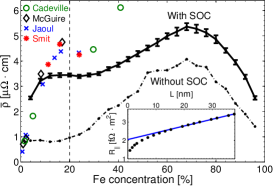
We calculate the electrical resistivity to illustrate our methodology. In the Landauer-Büttiker formalism, the conductance can be expressed in terms of the transmission matrix as Büttiker et al. (1985); Datta (1995). The resistance of the complete system consisting of ideal leads sandwiching a layer of ferromagnetic alloy of thickness is where is the Sharvin conductance of each lead with conductance channels per spin, is the interface resistance of a single NF interface, and is the bulk resistance of a ferromagnetic layer of thickness Schep et al. (1997); Xia et al. (2006). When the ferromagnetic slab is sufficiently thick, Ohmic behaviour is recovered whereby as shown in the inset to Fig. 1 for permalloy (Py = Ni80Fe20) and the bulk resistivity can be extracted from the slope of fn (2). For currents parallel and perpendicular to the magnetization direction, the resistivities are different and have to be calculated separately. The average resistivity is given by , and the anisotropic magnetoresistance ratio (AMR) is .
For permalloy we find values of Ohm-cm and AMR , compared to experimental low-temperature values in the range Ohm-cm for and for AMR Smit (1951). The resistivity calculated as a function of is compared to low temperature literature values Smit (1951); *McGuire:ieeem75; *Jaoul:jmmm77; *Cadeville:jpf73 in Fig. 1. The plateau in the calculated values around the Py composition appears to be seen in the experiments by Smit and Jaoul et al. Smit (1951); *Jaoul:jmmm77. The overall agreement with previous calculations is good Banhart and Ebert (1995); *Banhart:prb97. In spite of the smallness of the SOC, the resistivity of Py is underestimated by more than a factor of four when it is omitted, underlining its importance for understanding transport properties.
Three sources of disorder which have not been taken into account here will increase the calculated values of ; short range potential fluctuations that go beyond the single site CPA, short range strain fluctuations reflecting the differing volumes of Fe and Ni and spin disorder. These will be the subject of a later study.
Gilbert Damping.
Recently, Brataas et al. showed that the energy loss due to Gilbert damping in an NFN scattering configuration can be expressed in terms of the scattering matrix Brataas et al. (2008). Using the Landau-Lifshitz-Gilbert equation (1), the energy lost by the ferromagnetic slab is,
| (3) |
where is the unit vector of the magnetization direction for the macrospin mode. By equating this energy loss to the energy flow into the leads Avron et al. (2001); *Moskalets:prb02a; *Moskalets:prb02b associated with “spin-pumping” Tserkovnyak et al. (2002); *Tserkovnyak:prb02b,
| (4) |
the elements of the tensor can be expressed as
| (5) |
Physically, energy is transferred slowly from the spin degrees of freedom to the electronic orbital degrees of freedom from where it is rapidly lost to the phonon degrees of freedom. Our calculations focus on the role of elastic scattering in the rate-limiting first step.
Assuming that the Gilbert damping is isotropic for cubic substitutional alloys and allowing for the enhancement of the damping due to the FN interfaces Tserkovnyak et al. (2002); Zwierzycki et al. (2005); Mizukami et al. (2001); *Mizukami:jjap01, the total damping in the system with a ferromagnetic slab of thickness can be written where we express the bulk damping in terms of the dimensionless Gilbert damping parameter , where is the magnetization density and is the cross section. The results of calculations for Ni80Fe20 are shown in the inset to Fig. 2, where the derivatives of the scattering matrix in (5) were evaluated numerically by taking finite differences. The intercept at , , allows us to extract the damping enhancement Zwierzycki et al. (2005) but here we focus on the bulk properties and leave consideration of the material dependence of the interface enhancement for later study. The value of determined from the slope of is that is at the lower end of the range of values measured at room temperature for Py Mizukami et al. (2001); *Mizukami:jjap01; Bailey et al. (2001); Patton et al. (1975); *Ingvarsson:apl04; *Nakamura:jjap04; *Rantschler:ieeem05; *Bonin:jap05; *Lagae:jmmm05; *Nibarger:apl03; *Inaba:ieeem06; *Oogane:jjap06.
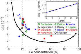
Fig. 2 shows the Gilbert damping parameter as a function of for Ni1-xFex binary alloys in the fcc structure. From a large value for clean Ni, it decreases rapidly to a minimum at and then grows again as the limit of clean fcc Fe is approached. Part of the decrease in with increasing can be explained by the increase in the magnetic moment per atom as we progress from Ni to Fe. The large values of calculated in the dilute alloy limits can be understood in terms of conductivity-like enhancement at low temperatures Bhagat and Lubitz (1974); *Heinrich:jap79 that has been explained in terms of intraband scattering Kamberský (1976); Gilmore et al. (2007); *Gilmore:jap08; *Kambersky:prb07. The trend exhibited by the theoretical is seen to be reflected by experimental room temperature results. In spite of a large spread in measured values, these seem to be systematically larger than the calculated values. Part of this discrepancy can be attributed to an increase in with temperature Bastian and Biller (1976); Bailey et al. (2001).
Spin diffusion.
When an unpolarized current is injected from a normal metal into a ferromagnet, the polarization will return to the value characteristic of the bulk ferromagnet sufficiently far from the injection point, provided there are processes which allow spins to flip. Following Valet-Fert Valet and Fert (1993) and assuming there is no spin-flip scattering in the N leads, we can express the fractional spin current densities as a function of distance from the interface as
| (6) |
where is the total current through the device, and are the currents of majority and minority electrons, respectively, is the spin-diffusion length, is the bulk resistivity and is the bulk spin asymmetry . The interface resistance , the interface resistance asymmetry and the interface spin-relaxation expressed through the spin-flip coefficient Park et al. (2000) must be taken into consideration resulting in a finite polarization of current injected into the ferromagnet. The corresponding expressions are plotted as solid lines in Fig. 3.
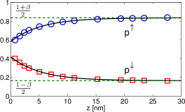
To calculate the spin-diffusion length we inject non-polarized states from one N lead and probe the transmission probability into different spin-channels in the other N lead for different thicknesses of the ferromagnet. Fig. 3 shows that the calculated values can be fitted using expressions (6) if we assume that , yielding values of the spin-flip diffusion length nm and bulk asymmetry parameter for Ni80Fe20 alloy compared to experimentally estimated values of for and in the range nm for Bass and Pratt Jr. (1999); *Bass:jpcm07.
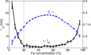
and are shown as a function of concentration in Fig. 4. The convex behaviour of is dominated by and tracks the large minority spin resistivity whose origin is the large mismatch of the Ni and Fe minority spin band structures that leads to a concentration dependence of Banhart and Ebert (1995). The majority spin band structures match well so is much smaller and changes relatively weakly as a function of . The increase of in the clean metal limits corresponds to the increase of the electron momentum and spin-flip scattering times in the limit of weak disorder.
In summary, we have developed a unified DFT-based scattering theoretical approach for calculating transport parameters of concentrated alloys that depend strongly on spin-orbit coupling and disorder and have illustrated it with an application to NiFe alloys. Where comparison with experiment can be made, the agreement is remarkably good offering the prospect of gaining insight into the properties of a host of complex but technologically important magnetic materials.
Acknowledgements.
This work is part of the research programs of “Stichting voor Fundamenteel Onderzoek der Materie” (FOM) and the use of supercomputer facilities was sponsored by the “Stichting Nationale Computer Faciliteiten” (NCF), both financially supported by the “Nederlandse Organisatie voor Wetenschappelijk Onderzoek” (NWO). It was also supported by “NanoNed”, a nanotechnology programme of the Dutch Ministry of Economic Affairs and by EC Contract No. IST-033749 “DynaMax.”References
- UMS (2005) in Ultrathin Magnetic Structures I-IV, edited by J. A. C. Bland and B. Heinrich (Springer-Verlag, Berlin, 1994-2005).
- van Son et al. (1987) P. C. van Son, H. van Kempen, and P. Wyder, Phys. Rev. Lett., 58, 2271 (1987).
- van Son et al. (1988) P. C. van Son, H. van Kempen, and P. Wyder, Phys. Rev. Lett., 60, 378 (1988).
- Valet and Fert (1993) T. Valet and A. Fert, Phys. Rev. B, 48, 7099 (1993).
- Gilmore et al. (2007) K. Gilmore, Y. U. Idzerda, and M. D. Stiles, Phys. Rev. Lett., 99, 027204 (2007).
- Gilmore et al. (2008) K. Gilmore, Y. U. Idzerda, and M. D. Stiles, J. Appl. Phys., 103, 07D303 (2008).
- Kamberský (2007) V. Kamberský, Phys. Rev. B, 76, 134416 (2007).
- Liu et al. (2009) C. Liu, C. K. A. Mewes, M. Chshiev, T. Mewes, and W. H. Butler, Appl. Phys. Lett., 95, 022509 (2009).
- Kamberský (1976) V. Kamberský, Czech. J. Phys., 26, 1366 (1976).
- Xia et al. (2001) K. Xia, P. J. Kelly, G. E. W. Bauer, I. Turek, J. Kudrnovský, and V. Drchal, Phys. Rev. B, 63, 064407 (2001).
- Xia et al. (2006) K. Xia, M. Zwierzycki, M. Talanana, P. J. Kelly, and G. E. W. Bauer, Phys. Rev. B, 73, 064420 (2006).
- Andersen et al. (1986) O. K. Andersen, Z. Pawlowska, and O. Jepsen, Phys. Rev. B, 34, 5253 (1986).
- Andersen (1975) O. K. Andersen, Phys. Rev. B, 12, 3060 (1975).
- Turek et al. (1997) I. Turek, V. Drchal, J. Kudrnovský, M. Šob, and P. Weinberger, Electronic Structure of Disordered Alloys, Surfaces and Interfaces (Kluwer, Boston-London-Dordrecht, 1997).
- Soven (1967) P. Soven, Phys. Rev., 156, 809 (1967).
- Büttiker et al. (1985) M. Büttiker, Y. Imry, R. Landauer, and S. Pinhas, Phys. Rev. B, 31, 6207 (1985).
- Datta (1995) S. Datta, Electronic Transport in Mesoscopic Systems (Cambridge University Press, Cambridge, 1995).
- Schep et al. (1997) K. M. Schep, J. B. A. N. van Hoof, P. J. Kelly, G. E. W. Bauer, and J. E. Inglesfield, Phys. Rev. B, 56, 10805 (1997).
- fn (2) The non-linearity of the resistance for in the inset to Fig. 1 has nothing to do with spin-orbit coupling. It already results when spin-dependent resistances of the form are added in parallel in the two-current series-resistor (2CSR) model; the total resistance only becomes linear for values of so large that the bulk resistances are much larger than the interface and Sharvin terms.
- Smit (1951) J. Smit, Physica, 17, 612 (1951).
- McGuire and Potter (1975) T. R. McGuire and R. I. Potter, IEEE Trans. Mag., 11, 1018 (1975).
- Jaoul et al. (1977) O. Jaoul, I. Campbell, and A. Fert, J. Magn. & Magn. Mater., 5, 23 (1977).
- Cadeville and Loegel (1973) M. C. Cadeville and B. Loegel, J. Phys. F: Met. Phys., 3, L115 (1973).
- Banhart and Ebert (1995) J. Banhart and H. Ebert, Europhys. Lett., 32, 517 (1995).
- Banhart et al. (1997) J. Banhart, H. Ebert, and A. Vernes, Phys. Rev. B, 56, 10165 (1997).
- Brataas et al. (2008) A. Brataas, Y. Tserkovnyak, and G. E. W. Bauer, Phys. Rev. Lett., 101, 037207 (2008).
- Avron et al. (2001) J. E. Avron, A. Elgart, G. M. Graf, and L. Sadun, Phys. Rev. Lett., 87, 236601 (2001).
- Moskalets and Büttiker (2002) M. Moskalets and M. Büttiker, Phys. Rev. B, 66, 035306 (2002a).
- Moskalets and Büttiker (2002) M. Moskalets and M. Büttiker, Phys. Rev. B, 66, 205320 (2002b).
- Tserkovnyak et al. (2002) Y. Tserkovnyak, A. Brataas, and G. E. W. Bauer, Phys. Rev. Lett., 88, 117601 (2002a).
- Tserkovnyak et al. (2002) Y. Tserkovnyak, A. Brataas, and G. E. W. Bauer, Phys. Rev. B, 66, 224403 (2002b).
- Zwierzycki et al. (2005) M. Zwierzycki, Y. Tserkovnyak, P. J. Kelly, A. Brataas, and G. E. W. Bauer, Phys. Rev. B, 71, 064420 (2005).
- Mizukami et al. (2001) S. Mizukami, Y. Ando, and T. Miyazaki, J. Magn. & Magn. Mater., 226–230, 1640 (2001a).
- Mizukami et al. (2001) S. Mizukami, Y. Ando, and T. Miyazaki, Jpn. J. Appl. Phys., 40, 580 (2001b).
- Bailey et al. (2001) W. Bailey, P. Kabos, F. Mancoff, and S. Russek, IEEE Trans. Mag., 37, 1749 (2001).
- Patton et al. (1975) C. E. Patton, Z. Frait, and C. H. Wilts, J. Appl. Phys., 46, 5002 (1975).
- Ingvarsson et al. (2004) S. Ingvarsson, G. Xiao, S. Parkin, and R. Koch, Appl. Phys. Lett., 85, 4995 (2004).
- Nakamura et al. (2004) H. Nakamura, Y. Ando, S. Mizukami, and H. Kubota, Jpn. J. Appl. Phys., 43, L787 (2004).
- Rantschler et al. (2005) J. O. Rantschler, B. B. Maranville, J. J. Mallett, P. Chen, R. D. McMichael, and W. F. Egelhoff, IEEE Trans. Mag., 41, 3523 (2005).
- Bonin et al. (2005) R. Bonin, M. L. Schneider, T. J. Silva, and J. P. Nibarger, J. Appl. Phys., 98, 123904 (2005).
- Lagae et al. (2005) L. Lagae, R. Wirix-Speetjens, W. Eyckmans, S. Borghs, and J. de Boeck, J. Magn. & Magn. Mater., 286, 291 (2005).
- Nibarger et al. (2003) J. P. Nibarger, R. Lopusnik, Z. Celinski, and T. J. Silva, Appl. Phys. Lett., 83, 93 (2003).
- Inaba et al. (2006) N. Inaba, H. Asanuma, S. Igarashi, S. Mori, F. Kirino, K. Koike, and H. Morita, IEEE Trans. Mag., 42, 2372 (2006).
- Oogane et al. (2006) M. Oogane, T. Wakitani, S. Yakata, R. Yilgin, Y. Ando, A. Sakuma, and T. Miyazaki, Jpn. J. Appl. Phys., 45, 3889 (2006).
- Bhagat and Lubitz (1974) S. M. Bhagat and P. Lubitz, Phys. Rev. B, 10, 179 (1974).
- Heinrich et al. (1979) B. Heinrich, D. J. Meredith, and J. F. Cochran, J. Appl. Phys., 50, 7726 (1979).
- Bastian and Biller (1976) D. Bastian and E. Biller, Phys. Stat. Sol. A, 35, 113 (1976).
- Park et al. (2000) W. Park, D. V. Baxter, S. Steenwyk, I. Moraru, W. P. Pratt, Jr., and J. Bass, Phys. Rev. B, 62, 1178 (2000).
- Bass and Pratt Jr. (1999) J. Bass and W. P. Pratt Jr., J. Magn. & Magn. Mater., 200, 274 (1999).
- Bass and Pratt Jr. (2007) J. Bass and W. P. Pratt Jr., J. Phys.: Condens. Matter, 19, 183201 (2007).