Tunable one-dimensional microwave emissions from cyclic-transition three-level atoms
Abstract
By strongly driving a cyclic-transition three-level artificial atom, demonstrated by such as a flux-based superconducting circuit, we show that coherent microwave signals can be excited along a coupled one-dimensional transmission line. Typically, the intensity of the generated microwave is tunable via properly adjusting the Rabi frequencies of the applied strong-driving fields or introducing a probe field with the same frequency. In practice, the system proposed here could work as an on-chip quantum device with controllable atom-photon interaction to implement a total-reflecting mirror or switch for the propagating probe field.
pacs:
42.50.Gy, 85.25.-j, 42.50.HzIntroduction.—Superconducting quantum circuits (SQCs) can be regarded as artificial atoms (AAs) with quantized energy levels martinis88 . Quantum mechanical behaviors in these AAs, such as spectroscopy spe1 ; spe2 ; spe3 , Rabi oscillations Rabi1 ; Rabi2 , and so forth, have already been demonstrated experimentally. Additionally, strong coupling between an AA and a single-mode microwave field in a high-Q resonator can realize a macroscopic analog of the cavity quantum electrodynamics (QED), known as circuit QED cQED1 ; cQED2 . While, when such an atom interacts with waves propagating freely along an open 1D transmission line (TL), the situation is qualitatively different. In this case, the system should be described by the continuous electromagnetic fields being scattered by a point-like AA Shen2005 ; NECscience2010 ; EITinAA ; OnChipAmplifer . Differing from the usual 3D scattering process, here the problem of spatial-mode mismatch between the incident and scattered waves can be effectively overcome as these waves are confined in the 1D space Shen2005 ; NECscience2010 . This also provides a way to demonstrate the strong interactions between the 1D microwave fields and an AA based on flux-biased superconducting circuit NECscience2010 ; EITinAA ; OnChipAmplifer . Specifically, by virtue of the tunability, controllability, and strong atom-photon coupling, these on-chip macroscopic quantum devices could be utilized to reproduce certain typical quantum optical phenomena, e.g., resonance fluorescence NECscience2010 , electromagnetically induced transparency (EIT) EITinAA , and ultimate on-chip amplifier OnChipAmplifer , etc..
In this paper, we discuss the feasibility of generating microwave with specific frequency along an open 1D TL by manipulating the strong-field-induced coherence in a coupled three-level -type AA martinis88 ; DeltaAtom1 ; DeltaAtom2 . The produced microwave emission can be controlled by introducing another weak probe field with the same frequency. Our results display some special 1D quantum optical phenomena in microwave domain and provide the potential applications in on-chip photonic quantum information processings with SQCs.
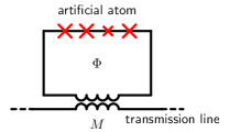
Tunable microwave emissions from a -type artificial atom.—We consider a system schematized in Fig. 1, where a superconducting loop interrupted by four Josephson junctions couples to an open 1D TL through the loop-line mutual inductance . The loop can be looked on as a multilevel AA, whose energy levels and transition elements can be tuned by adjusting the external magnetic flux . At some working points OnChipAmplifer , the desirable three-level -type transition configurations can be realized DeltaAtom1 ; DeltaAtom2 . Here we assume () and are the three selected levels and their eigenfrequenies of the -type AA. Three coherent driving fields (, ), propagating along the open 1D TL with the wave vectors and frequencies , are applied to couple the three possible transition-channels of the point-like AA located at . The Hamiltonian of this system can be written as . Here are the atomic projection or transition operators, and are the Rabi frequencies. The dipole moment matrix elements can be written as , where () are the dimensionless matrix elements, is the line-atom mutual inductance, and is the amplitude of the persistent current in the loop.
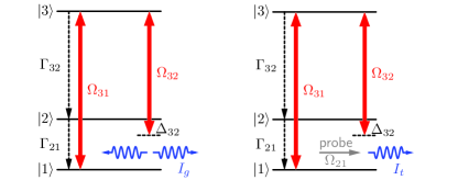
In the following, we will show that two strong-driving fields and can induce an effective magnetic flux with oscillating frequency in the AA-loop. And consequently, the AA as a point-like source, will emit microwaves with frequency in the TL. Specifically, we assume is resonantly applied between the levels and , and applied between the levels and with a detuning , as shown in Fig. 2(a). In the interaction picture, the Hamiltonian of this driven three-level system reads , and its corresponding dynamics can be described by the master equation
| (1) |
with being the density matrix. The Lindblad term is defined by .
Under the usual steady-state condition, the density matrix element (which describes the coherence between and ) can be written as
| (2) |
with , . Here can be defined as the detuning of the induced wave. Based on the experimental detections OnChipAmplifer , we have , , and , . As a consequence, the steady populations at resonant point read , , and , where . Thus (at resonant point ) can be simplified as
| (3) |
This implies that an additional magnetic flux threading the AA-loop can be induced, where is the related atomic dipole-moment operator. Note that this flux is originated from the nonzero dipole-transition elements between any pair of levels, which can only be realized in the present -type AA with the broken parity-symmetry.
Certainly, this induced oscillating flux in the AA-loop could produce mutually a microwave current along the TL, which satisfies the relevant 1D wave equation:
| (4) |
where is the phase velocity ( and are inductance and capacitance per unit length, respectively) and the dispersion relation is . The above equation describes a point-like AA located at with oscillating flux emitting microwave in the 1D TL. With the relation (with being the line impedance) NECscience2010 , the solution of Eq. (4) can be expressed as (representing the induced waves propagating in both directions) with the complex amplitude , and . Thus the intensity of the induced microwave current reads: . Specifically, at the resonant point, is determined by
| (5) |
and could be controlled via adjusting the values of the applied Rabi frequencies. For example, if and are modulated synchronously, i.e., , then is monotonically increasing with , approaching for sufficiently large . Typically, the upper limit of the produced microwave current is achieved for .
The above microwave emission could be further controlled by applying a probe field to couple the levels and , as shown in Fig. 2(b). At the resonant point and under the weak probe approximation, the according steady-state coherence term is
| (6) |
with
Clearly, the net microwave propagating along the 1D TL reads . And the amplitude of resulting current at can be expressed as , namely, a superposition of the incident probe and the wave mainly induced by the strong driving fields. Utilizing the expression for and , the intensity of the total microwave current can be written as . For strong driving fields, the second term in Eq. (6) is much smaller than the first term in Eq. (6) and sup , and can then be neglected when calculating . Note that this approximation is optimal if choosing , resulting in vanishing of the second term in Eq. (6). Consequently, at resonant point, can be rewritten as
| (7) |
with , and (where is the phase factor of ).
The above calculations indicate that: (1) For the fixed complex Rabi frequencies and , can still be modulated by changing the complex Rabi frequency of the probe . Particularly, when , , the induced microwave current at is totally switched off (i.e., ). Certainly, in this case the induced microwave current at remains unchanged and thus the relevant microwave emission from the AA is unidirectional. (2) Alternatively, if the probe is treated as a signal, the above strong-field-driven AA can be regarded as a total reflection mirror for the probe field. Originally, in the absence of the strong-driving fields, a weak probe field propagating along the 1D TL can be partially absorbed (reflected) by resonantly interacting with the AA. The reflection amplitude could be expressed as , if the atom-line coupling efficiency is unit NECscience2010 . Therefore, only when the pure dephasing () is negligible, the AA can work as the desirable reflection mirror. Our calculations show that, this shortcoming could be overcome by appropriately applying the two strong-driving fields and satisfying ; . Under this condition, despite of remarkable pure dephasing (note that is a function of ), the incident probe field can be completely canceled out because of its destructive interference with the strong-field-induced wave. Consequently, an interesting strong-field-induced absorption (reflection) phenomenon can be realized.

Experimental feasibility.— Immediately, the phenomena predicted above could be verified with the recent experimental device NECscience2010 ; EITinAA ; OnChipAmplifer , i.e., an open 1D TL couples to an AA based on superconducting flux qubit geometry. For the four-junction flux qubit proposed there, by tuning the flux bias (with being the flux quantum) slightly apart from the point , a cyclic-transition structure can be realized with the lowest three levels. Typically, if the flux bias is set as , the corresponding experimental parameters of AA are MHz, MHz, MHz, GHz, GHz OnChipAmplifer . Also, the characteristic impedance of the coplanar TL is EITinAA . Furthermore, we assume that the Rabi frequencies of the applied two strong-driving fields could be set as MHz. With these parameters, numerical simulations are carried out, and the results are presented in Figs. 3-5.
We plot the induced microwave emission spectrum in Fig. 3(a). It is seen that, around the resonant point , an obvious emission peak appears with maximal amplitude nA, which is in good agreement with the above theoretical estimation utilizing Eq. (5). In addition, Fig. 3(b) shows the influence of driving fields on (Here, ). We can see that a remarkable microwave current can be obtained when the driving fields are comparable with . It reaches nA, if the control fields are strong enough. This is in good accordance with the theoretical prediction () given above. To attain a more remarkable induced current, one can enhance either or . On one hand, a smaller decoherence rate may lead to a larger . Note that in the limit of , the upper limit of induced current is nA. On the other hand, as , one can enlarge by choosing sample with smaller line impedance and larger loop-line mutual inductance .
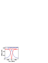
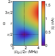
Fig. 4(a) shows that, when a probe field with , MHz (satisfying ) is applied, the original induced microwave emission peak (dashed line, repeating the spectrum in Fig. 3 (a)), will be changed into a dip with zero emission at resonant point (solid line). This indicates that the total suppression for the emission current at , which is in accordance with the above theoretical estimation. Fig. 4(b) displays as a function of and (The detuning is fixed at ). This verifies that the probe parameters used in Fig. 4(a) are optimal for implementing the desirable switch-off operation.
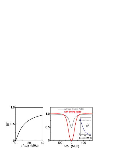
By setting , the power transmission coefficient () as a function of pure dephasing (other atom parameters are the same as previous discussion), for a resonantly incident weak probe with MHz, is shown in Fig. 5(a). One can see that, only in the ideal case of the atom can be regarded as a total reflection mirror with . However, when the pure dephasing is not negligible, only partial power can be reflected by the atom. Typically, for a probe with MHz interacting with an AA with pure dephasing MHz (gotten from AA parameters in Ref. OnChipAmplifer ), at resonant point the according power transmission coefficient is only about (gray line in Fig. 5(b)). When the two strong fields with MHz (satisfying ), are applied, at the resonant point, the power extinction for the same probe is reaching the ideal case of 100% (red line in Fig. 5(b)), displaying the phenomenon of strong-field-induced absorption (single atom total reflection mirror). Moreover, the inset in Fig. 5(b) shows by fixing other parameters and decreasing from MHz to about MHz, the resonant probe signal can be tuned from completely reflection to totally transmission, demonstrating a perfect single AA switch for propagating probe. Also, the inset verifies when , the AA will work as an on-chip amplifier OnChipAmplifer .
Conclusions.—In summary, we have proposed an approach to realize strong-field-induced microwave emission by a single AA coupled to 1D open space of a TL. Moreover, we have shown that this kind of induced microwave emission is controllable and tunable by another weak probe. Although various quantum optical effects based on multilevel structure of superconducting AAs have been demonstrated in a series of recent experiments EITinAA ; ATinSQC1 ; ATinSQC2 ; CPTinSQC , our results show certain novel effects in the 1D quantum optics at microwave regime. On the other hand, the quantum devices with these effects may have interesting applications in photonic quantum information processing utilizing SQCs. Substantially, the generation of induced microwave emission is a frequency conversion process. This indicates that the proposed device may be used to connect superconducting quantum devices operating at different frequencies in the future SQCs. Finally, the device can also be used as tunable coherent microwave source, or total reflection mirror (single AA quantum switch) controlling the propagation of 1D probe field.
Acknowledgements.
The project was supported in part by National Natural Science Foundation of China under Grant Nos. 10874142, 90921010, and the National Fundamental Research Program of China through Grant No. 2010CB923104.References
- (1) J. Clark, A. N. Cleland, M. H. Devoret, D. Esteve, and J. M. Martinis, Science 239, 992 (1988).
- (2) J. R. Friedman, V. Patel, W. Chen, S. K. Tolpygo, and J. E. Lukens, Nature (London) 406, 43 (2000).
- (3) C. H. van der Wal, A. C. J. ter Haar, F. K. Wilhelm, R. N. Schouten, C. J. P. M. Harmans, T. P. Orlando, S. Lloyd, and J. E. Mooij, Science 290, 773 (2000);
- (4) A. J. Berkley, H. Xu, R. C. Ramos, M. A. Gubrud, F. W. Strauch, P. R. Johnson, J. R. Anderson, A. J. Dragt, C. J. Lobb, and F. C. Wellstood, Science 300, 1548 (2003).
- (5) D. Vion, A. Aassime, A. Cottet, P. Joyez, H. Pothier, C. Urbina, D. Esteve, and M. H. Devoret, Science 296, 886 (2002).
- (6) Chiorescu, Y. Nakamura, C. J. P. M. Harmans, and J. E. Mooij, Science 299, 1869 (2003).
- (7) A. Wallraff, D. I. Schuster, A. Blais, L. Frunzio, R. S. Huang, J. Majer, S. Kumar, S. M. Girvin, and R. J. Schoelkopf, Nature (London) 431, 162 (2004);
- (8) A. Blais, R. S. Huang, A. Wallraff, S. M. Girvin, and R. J. Schoelkopf Phys. Rev. A 69, 062320 (2004).
- (9) J. T. Shen and S. Fan, Phys. Rev. Lett., 95, 213001 (2005).
- (10) O. Astafiev, A. M. Zagoskin, A. A. Abdumalikov Jr., Y. A. Pashkin, T. Yamamoto, K. Inomata, Y. Nakamura and J. S. Tsai, Science 327, 840 (2010).
- (11) A. A. Abdumalikov, Jr., O. Astafiev, A. M. Zagoskin, Yu. A. Pashkin, Y. Nakamura, and J. S. Tsai, Phys. Rev. Lett. 104, 193601 (2010).
- (12) O. Astafiev, A. A. Abdumalikov, Jr., A. M. Zagoskin, Yu. A. Pashkin, Y. Nakamura, and J. S. Tsai, Phys. Rev. Lett. 104, 183603 (2010).
- (13) Yu-xi Liu, J. Q. You, L. F. Wei, C. P. Sun, and F. Nori, Phys. Rev. Lett. 95, 087001 (2005).
- (14) L. F. Wei, J. R. Johansson, L. X. Cen, S. Ashhab, and Franco Nori, Phys. Rev. Lett. 100, 113601 (2008); W. Z. Jia and L. F. Wei, Phys. Rev. A 82, 013808 (2010).
- (15) With the experimental parameters in Ref. OnChipAmplifer , numerical calculation shows that if , , , then , .
- (16) M. Baur, S. Filipp, R. Bianchetti, J. M. Fink, M. Goppl, L. Steffen, P. J. Leek, A. Blais, and A. Wallraff, Phys. Rev. Lett. 102, 243602 (2009).
- (17) M. A. Sillanpa, Jian Li, K. Cicak, F. Altomare, J. I. Park, R. W. Simmonds, G. S. Paraoanu, and P. J. Hakonen, Phys. Rev. Lett. 103, 193601 (2009).
- (18) W. R. Kelly, Z. Dutton, J. Schlafer, B. Mookerji, T. A. Ohki, J. S. Kline and D. P. Pappas, Phys. Rev. Lett. 104, 163601 (2010).