Multi-mode mediated exchange coupling in cavity QED
Abstract
Microwave cavities with high quality factors enable coherent coupling of distant quantum systems. Virtual photons lead to a transverse exchange interaction between qubits, when they are non-resonant with the cavity but resonant with each other. We experimentally probe the inverse scaling of the inter-qubit coupling with the detuning from a cavity mode and its proportionality to the qubit-cavity interaction strength. We demonstrate that the enhanced coupling at higher frequencies is mediated by multiple higher-harmonic cavity modes. Moreover, in the case of resonant qubits, the symmetry properties of the system lead to an allowed two-photon transition to the doubly excited qubit state and the formation of a dark state.
pacs:
42.50.Ct, 03.67.Lx, 42.50.Pq, 85.35.GvI Introduction
Experiments on single photons coupled strongly to single (artificial) atoms Haroche and Raimond (2006) allow for in-depth studies of photon-atom interactions on a single particle level. This has first been demonstrated with individual atoms coupled to microwave Meschede et al. (1985); Raimond et al. (2001) and later optical cavity fields Miller et al. (2005); Walther et al. (2006). In solids, strong coupling has been achieved with quantum dots Reithmaier et al. (2004); Yoshie et al. (2004) and superconducting circuits Wallraff et al. (2004). Despite the diversity of physical realizations the coherent exchange of energy between photons and atoms can be described in all these systems by a generic model named after Jaynes and Cummings Jaynes and Cummings (1963).
In circuit quantum electrodynamics experiments, superconducting quantum circuits are coupled to single microwave photons in a planar transmission line cavity Blais et al. (2004). In this configuration, coupling strengths exceed decay rates by two orders of magnitude, and strong resonant coupling between a microwave cavity and a single Wallraff et al. (2004); Blais et al. (2004); Houck et al. (2007); Fink et al. (2008); Hofheinz et al. (2009) or multiple Sillanpää et al. (2007); Fink et al. (2009) superconducting qubits has been observed. In the case of finite detuning between a single qubit and a resonator mode, energy exchange between the individual systems is strongly suppressed due to energy conservation. In this dispersive regime, a residual interaction mediated via virtual photons induces a finite Lamb Fragner et al. (2008) and ac-Stark shift Schuster et al. (2005) of the energy levels. For two qubits coupled to a common cavity field, the same mechanism leads to an interaction mediated by virtual photons Gywat et al. (2006) as experimentally demonstrated Majer et al. (2007). This coupling is similar to the J-coupling of interacting nuclear spins as observed in nuclear magnetic resonance experiments (e. g. Abragam (1961); Vandersypen and Chuang (2004)). It is also a dominant interaction of double quantum dots, where the exchange splitting between spin singlet and spin triplet state can be used to control a logical qubit state encoded in a two-electron spin-state Petta et al. (2005). In contrast to these local interactions, and also opposed to the direct coupling of superconducting quantum circuits Yamamoto et al. (2003); McDermott et al. (2005); Steffen et al. (2006); Hime et al. (2006); Niskanen et al. (2007); Plantenberg et al. (2007); Neeley et al. (2010), the coupling mediated via virtual resonator photons allows for a long-range interaction between two or more distant superconducting qubits. In the context of quantum information processing, it can be used to realize two-qubit gates Blais et al. (2007) with superconducting qubits DiCarlo et al. (2009, 2010); Neeley et al. (2010).
In this paper we measure the exchange coupling as a function of detuning of two qubits from a single or multiple resonator modes and characterize the symmetry properties of the coupled system. In Section II the inter-qubit coupling mechanism and its spectroscopic measurement is outlined. In Section III the coupling near a single resonator mode is analyzed. In Section IV higher harmonic modes of the transmission line resonator are included in the analysis. Section V and VI describe the formation of a dark state at the avoided level crossing and the observation of a two-photon transition from the ground to the doubly excited state that is allowed only at qubit resonance.
II Exchange coupling mechanism
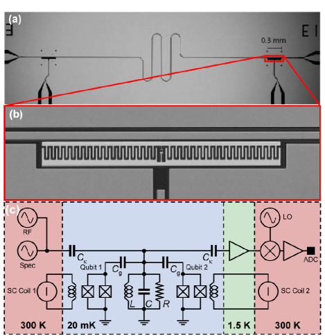
In our experiments two superconducting qubits are dispersively coupled to a microwave cavity, see Fig. 1. The quantum circuits are realized as weakly anharmonic transmon qubits Koch et al. (2007) and the cavity is formed by a coplanar-waveguide resonator supporting several harmonic modes Göppl et al. (2008).
In the dispersive regime, the detuning is larger than the coupling strength of both qubits () to each resonator mode . The relevant Hamiltonian
| (1) | ||||
is obtained by adiabatically eliminating the direct qubit-resonator interaction of the qubits for each harmonic mode in the Jaynes-Cummings Hamiltonian Blais et al. (2007). The first term denotes the qubit Hamiltonian with Lamb-shifted transition frequencies from the ground to the first excited state. Higher transmon levels do not play a role in our experiments and are therefore neglected. The second term in Eq. (1) describes the resonator modes with frequencies , integer multiples of the fundamental frequency , shifted by the cavity pulls Blais et al. (2007); Filipp et al. (2009). Finally, the third term describes the effective qubit-qubit coupling, also called J-coupling or transverse exchange coupling,
| (2) |
a flip-flop interaction mediated by virtual photon exchange.
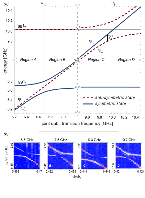
The transverse exchange coupling in Eq. (2) leads to an avoided level crossing of the excited qubit states Majer et al. (2007). At qubit-resonance, where , the size of the splitting is . The new eigenstates are the symmetric triplet states , and , as well as the anti-symmetric singlet state , see Fig. 2(a). In the maximally entangled states a single excitation is shared between the two qubits. More generally, for the eigenstates of the Hamiltonian in Eq. (1) can be parametrized as
| (3) | ||||
with the mixing angle determined by and . The separable qubit states and are asymptotically realized, and , for large qubit-qubit detunings (), as indicated in Fig. 2(b).
We have performed two sets of experiments using samples with different parameters listed in table 1. In these experiments, the energy spectrum of the coupled qubits is probed by monitoring the transmission through the resonator while applying a second spectroscopy tone Schuster et al. (2005) at frequency . For the spectroscopy measurement shown in Fig. 2(b), the first qubit is kept at a fixed frequency and the second qubit frequency is swept across the avoided crossing by changing its flux bias using external coils. The value of can be extracted from a fit of the upper and lower branch of the avoided crossing to the function
| (4) |
where is in this parameter regime an approximately linear function of the flux threading the second qubit loop. The fit parameters are the transition frequency of the first qubit and the coupling strength . Both are determined with a precision of typically better than . In this particular example we find and .
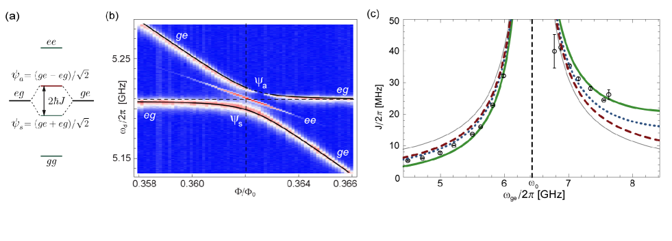
Two additional features are observed in Fig. 2(b). First, a third spectroscopic line centered between the upper and the lower branch appears at higher drive powers. This is a signature of a two-photon transition from the ground state () to the doubly excited state () of the coupled qubit system that is only allowed directly at the anti-crossing. This is discussed in Section VI. Second, the upper branch shows a transition to a dark resonance at the avoided crossing, which can be explained by the symmetry of the states with respect to the spectroscopic drive, see Section V.
III Coupling to the fundamental resonator mode
According to Eq. (2) the coupling scales inversely with the detuning , considering only a single resonator mode. We have recorded the avoided crossing between the two qubits at different detunings from the fundamental mode of the resonator using a spectroscopic measurement performed on sample A. The corresponding parameters are listed in Table 1. The measured values of shown in Fig. 2(c) are determined for each detuning from a fit as described in Section II.
| Parameter | Sample A | Sample B |
|---|---|---|
| 6.44 GHz | 3.34 GHz | |
| 1.57 MHz | 1.91 MHz | |
| 232 MHz | 148 MHz | |
| 233 MHz | 153 MHz | |
| 35 GHz | 409 GHz | |
| 38 GHz | 375 GHz | |
| 133 MHz | 43 MHz | |
| 134 MHz | 42 MHz |
Considering only one relevant resonator mode and constant , the strength of the inter-qubit coupling is expected to be symmetric about the resonator frequency (Eq. (2); thin gray line in Fig. 2(c)). The asymmetry in the data can partly be accounted for by including the frequency-dependence of the coupling , as explained in Appendix A. It follows from the transition matrix elements that scales proportional to the transition frequency of the qubits. This scaling factor leads to an asymmetry of the exchange coupling around the resonance frequency that improves the agreement with the data (dashed red line, Fig 2(c)). To check, whether the remaining discrepancy originates from the dispersive approximation, we have also done a numerical diagonalization of the full generalized Jaynes-Cummings Hamiltonian (not shown). This calculation agrees with the dispersive model within the errors of the experimentally determined values of .
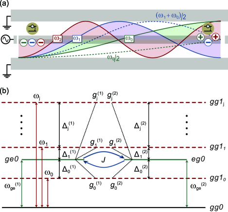
For a quantitative agreement, higher harmonics of the resonator have to be considered. The particular implementation of the resonator as an open-ended coplanar waveguide supports higher harmonics at integer multiples of the fundamental frequency Göppl et al. (2008), see Fig. 3(a). Each of these higher modes provides a channel for the exchange of virtual photons between the qubits determined by the detuning and the coupling to the harmonic mode as indicated in Fig. 3(b). Above the fundamental mode, the coupling to the first harmonic mode contributes significantly to the qubit-qubit coupling, which results in an asymmetry with respect to the detuning . Including four modes in Eq. (2) to determine the expected value of , good agreement with data is obtained (thick green line, Fig. 2(c)).
It is important to also include the alternating sign of the electric fields at the qubits’ position in the calculations. As depicted schematically in Fig. 3(a), the electric field of the fundamental and higher even modes (j=0, 2, 4,…) have always opposite sign, i. e. a relative phase of , at either end of the microwave cavity, whereas odd modes (j=1, 3, 5,…) have equal sign. Thus, higher harmonics add with different signs to the effective coupling strength. A priori, the sum in Eq. (2) has to be extended over all modes. The sum does, however, not converge, as discussed also in the context of Purcell-limited qubit decay rates in Houck et al. (2008). The proportionality of the coupling (Eq. 7) together with the same proportionality of the detuning for large leads to an non-converging series alternating between the two values
Apparently, a cut-off frequency has to be imposed to obtain physical results.
In Fig. 2(c) we have also included a plot of when terminating the sum at the fourth harmonic () (dotted blue line). It is observed that the difference between an even and odd number of modes is significant, up to of the coupling strength. We have also verified that this is not an artifact of the dispersive model by numerically diagonalizing the Jaynes-Cummings Hamiltonian.
In our measurements we observe enhancement of the exchange coupling, inversely proportional to the detuning of the qubits to the cavity mode. The asymmetry around the mode is attributed to higher harmonic modes that contribute to the measured (renormalized) . However, to compute the coupling strength the number of included modes has to be restricted by imposing a high-frequency cut-off. Physically, there are several mechanisms conceivable. The energy needed to overcome the pairing interaction of Cooper pairs sets an upper frequency of about for Niobium. The electric field across the transmon averages out when the wavelength of the photons becomes comparable to the size of the transmon at a frequency of about . Also, radiation or dielectric loss mechanisms and the photon loss rate through the coupling capacitors increase at higher frequencies Houck et al. (2008). Current experiments are, however, not designed to work at frequencies higher than approx. . The exploration of the relevant frequency range will require an elaborate circuit architecture and will be challenging with current technology.
IV Multi mode coupling
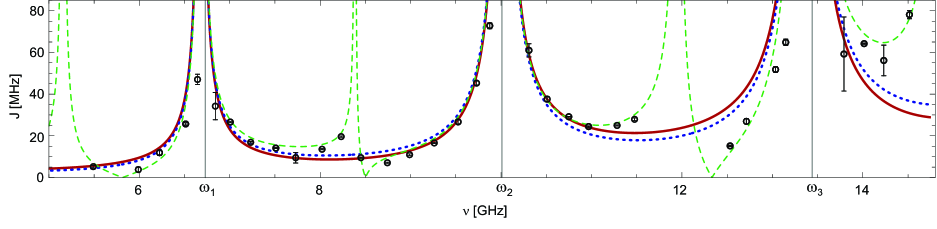
To assess the coupling to higher-order modes, we measure the qubit-qubit coupling strength as a function of qubit transition frequency in a second sample B over a broader frequency range. In this sample the frequency of the fundamental resonator mode is lower, , and the maximal Josephson energy is higher by about one order of magnitude (see Table 1 - sample B). As a result, the qubit transition frequency can be swept over several resonator modes.
The measured inter-qubit coupling strength shows an enhanced value around each harmonic mode, as well as an overall increase with frequency (Fig. 4) in agreement with the discussion in Sec. III. A calculation based on the dispersive Jaynes-Cummings Hamiltonian can explain the data qualitatively. However, including an even (, solid red line) or an odd (, dotted blue line) number of resonator modes yields again significant differences in the calculated value of , neither of the curves resulting in good quantitative agreement.
The resonator modes discussed so far cannot fully explain the measured inter-qubit coupling. Large deviations located asymmetrically around and (Fig. 4) hint at the presence of an additional coupling mechanism at these intermediate frequencies. The measurement reveals that the coupling strength is asymmetrically modified between every two resonances alluding to an anti-resonance that mediates a qubit-qubit coupling channel of similar magnitude as the coplanar waveguide resonance. This can lead to an enhancement or suppression of the qubit-qubit coupling at intermediate frequencies due to interference between multiple resonances.
To account for these spurious resonances, additional field modes are included in the model. Physically, these modes may be identified as the slotline modes of the coplanar waveguide, a differential excitation of the left and right ground plane Wolff (2006). Air-bridges or wire-bonds that connect the ground planes could effectively suppress these modes, but have not been implemented in this sample. Treating these modes equivalently to the coplanar waveguide modes in the derivation of the dispersive multi-mode Jaynes-Cummings Hamiltonian (1), an extra contribution to the exchange coupling emerges,
is then fitted to the data in Fig. 4 assuming that the coupling strengths of both qubits are equal in magnitude, , but have – like the coplanar waveguide modes – alternating sign, with . For the fit we take four extra modes into account () from which we obtain the resonance frequencies . Note, that these additional modes are not observed in simple transmission measurements Göppl et al. (2008) of the resonator and their frequencies can therefore not be determined independently. In the same fit the ratios are determined to , which shows that the coupling strengths to the spurious modes and to the coplanar waveguide modes are similar in strength. This similarity hints at a highly localized field of the spurious mode with small effective mode volume. Also, the relative sign between the couplings and of the qubits to the spurious mode alternate with the mode number . This implies that the field of the spurious modes has also either equal or opposite direction at the position of the qubits, like the coplanar waveguide mode outlined in Fig. 3. The qualitative agreement to the measured values of J is considerably improved by the inclusion of these extra modes, see dashed green line in Fig. 4.
The measured values of the exchange coupling demonstrate the sensitivity of the qubit-qubit coupling to the full mode structure of the circuit. While a single-mode model is sufficient around a single resonance, quantitative predictions require complete knowledge of designed and spurious resonances. Appropriate circuit design and use of wire-bond or air-bridge connections of ground-planes on the chip can short out spurious modes. In contrast, additional resonances can also be incorporated on purpose into the circuit design Reed et al. (2010) to modify the qubit-qubit coupling at certain frequencies.
V Dark state
A characteristic feature of the avoided level crossing is the observation of a dark resonance, where the transition from the ground state to the upper energy branch is forbidden and no signal is observed in spectroscopy measurements, see Fig. 2(b). In fact, the symmetry of the states at the avoided crossing leads to a selection rule with respect to the spectroscopic drive Blais et al. (2007); Majer et al. (2007)
| (5) |
through the resonator. To see this, we decompose the eigenvalues of the dispersive Hamiltonian (1) into triplet states and a singlet state. These are the eigenstates of the permutation operator (Eq. 8) to the eigenvalue . Explicitly, the triplet states (ground state), (doubly excited state) and the symmetric state span the symmetric subspace, whereas the singlet state is anti-symmetric under permutation of the qubits. This is equivalent to a decomposition of the system into a spin-1 and a spin-0 particle. The sign of the coupling constants determines the drive symmetry. Equal (opposite) sign of the electric field at the position of the two qubits leads to the positive (negative) sign of the second term in Eq. (5) and, consequently, to a(n) (anti-)symmetric excitation. For equal sign of the couplings, the drive term and the permutation operator commute (symmetric drive). Then, only transitions between states of same symmetry are allowed (see Appendix B) and the anti-symmetric state stays dark at zero detuning. Vice versa, for opposite sign of the couplings the now anti-symmetric drive can connect symmetric to anti-symmetric states.
In our experiments the symmetry of the drive is determined by the frequency of the microwave signal and the distance between the qubits. The relative sign of the field at the qubit positions is determined by the phase difference of the travelling wave between the qubits. Here, we have used the dispersion relation with the propagation velocity of light in the transmission line. As the qubits are located at the end of the transmission line resonator, is approximately the length of the resonator and sign changes happen at frequencies with , in between two resonances as indicated by the dotted lines in Fig. 3(a).
Whether the eigenstate with lower or higher energy is dark, depends – in the simplest model with only a single dominant resonator mode – on the qubit-resonator detuning. The higher () and lower () energy eigenstate of the Hamiltonian (1) at the avoided crossing can according to Eq. (3) be written as . Note, that in this notation the subscript denotes higher () or lower () energy and not the symmetry of the state. In Fig. 5 the energy levels of the coupled resonator-qubits system are plotted as a function of the qubit transition frequencies, which are kept equal, along with their respective symmetries. For a coupling to the first harmonic mode below the mode (, ) and above the mode (, ). Consequently, below the first harmonic the higher energy state is the anti-symmetric singlet state. This state cannot be excited from the ground state with a symmetric drive and stays dark (Fig. 5(b) - sub-panel A). At the avoided crossing with a resonator mode the lower and higher energy qubit state swap their symmetry due to the sign change of the detuning. Since the drive does not change its symmetry, also the dark and bright state energies are interchanged and the dark state appears at the lower branch (Fig. 5(b) - sub-panel B). The dark state is always closer in frequency to the resonator transition.
If the second harmonic mode dominates the coupling, the situation is reversed since the coupling constants have different signs. Below this mode, the (higher energy) state is symmetric, and (lower energy) is anti-symmetric. Still, the dark state appears at the upper branch of the avoided crossing (Fig. 5(b) - sub-panel C) and switches to the lower branch above the resonator (Fig. 5(b) - sub-panel D). The reason is that the drive symmetry changes as well in between two resonator modes as explained above, implying that the drive field changes from a symmetric (around the first harmonic mode) to an anti-symmetric drive (around the second harmonic mode). The drive can then induce transitions between the ground and an anti-symmetric state, but not to the symmetric state of the upper branch. The various conditions leading to the identification of the dark state branch are summarized in table 2. In particular, if the drive (line 4) has different symmetry than the higher energy state (line 3), remains dark.
| Region: | A | B | C | D |
|---|---|---|---|---|
| symm. | ||||
| drive symm. | ||||
| dark state |
VI Two-photon transition
The spectroscopic line between upper and lower branch of the avoided level-crossing in Fig. 2(b) is a two-photon transition from the ground state to the doubly excited state . Similarly, this transition has also been observed in a phase qubit coupled coherently to a two level fluctuator in the tunnel barrier of the Josephson junction comprising the qubit Bushev et al. (2010) and in molecular spectroscopy of two nearby molecules Hettich et al. (2002). It becomes visible only at the center of the avoided level crossing, again a manifestation of the symmetry properties of the system. The rate of the corresponding two-photon transition Loudon (2000)
is given by a sum over the intermediate states . Off the avoided crossing the qubits are effectively decoupled. In this case the intermediate states are . The transition is then prohibited due to destructive interference between the two possible paths, or , connecting the ground to the doubly excited state. Due to the opposite sign of the detunings , the two terms in the sum cancel and the transition rate . With the qubits at resonance, the intermediate states are and one term in the sum vanishes due to the forbidden transition to the dark state. With only one possible path connecting the to the state, no interference takes place and the transition becomes allowed. The enhanced transition rate can be employed for directly creating the maximally entangled state .
VII Conclusion
We have analyzed the coupling between two distant qubits mediated by the harmonic modes of a resonator. We have observed an overall increase of the exchange coupling with frequency as expected from a model including higher-harmonic modes of the coplanar waveguide resonator. Good qualitative agreement over a wide frequency range between the dispersive model and experimental data is obtained when taking spurious resonances of the coplanar waveguide in addition to the coplanar waveguide modes into account. Hence, measurements of the transverse inter-qubit coupling can be employed to detect and investigate spurious global coupling channels between distant qubits, complementary to measurements of single qubit spectra used to detect spurious local resonances Simmonds et al. (2004); Martinis et al. (2005). How many higher harmonic modes to include in the theory, i. e. where to set a high-frequency cut-off, can, however, not be decided on the basis of current measurements.
In addition, we have observed dark states and enhanced two-photon absorption at the avoided level crossing in spectroscopic measurements. These characteristic features are based on the relation between the symmetry of the drive and the singlet and triplet states formed by the coupled qubits, which also explains the dark state at either the lower or higher energy branch. These symmetries also affect decay processes of singlet and triplet states and, together with the non-trivial environment formed by the microwave resonator, dissipative dynamics of separable and entangled states can be studied. The exchange coupling can also be useful for building two-qubit gates when fast flux-pulses are applied to tune the qubits into resonance. In the context of quantum information processing, the resulting SWAP gate forms a universal two-qubit gate with short operation times. Moreover, the transverse exchange coupling mechanism described in this article mediates interaction not only between two, but an arbitrary number of distant qubits, an interesting playground for studies of collective phenomena with superconducting circuits, where the interaction is not restricted to nearest-neighbours.
The authors acknowledge useful discussions with A. Blais. Also, the group of M. Siegel is acknowledged for the preparation of Niobium films. This work was supported by Swiss National Science Foundation (SNF), Austrian Science Foundation (FWF) and ETH Zurich.
Appendix A Frequency-dependence of the qubit-resonator coupling
The coupling to the resonator is proportional to the rms voltage fluctuations of the vacuum field at the position of the -th qubit and to the off-diagonal matrix element Blais et al. (2004); Koch et al. (2007) of the charge operator ,
| (6) |
The prefactor is determined by the geometry of the circuit used in our experiments. In the large limit, realized in the devices, the matrix element is proportional to the square-root of the qubit transition frequency, . The vacuum field is proportional to the square root of the mode frequency, Blais et al. (2004); Haroche and Raimond (2006).
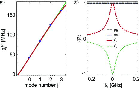
For a single qubit on resonance with the -th resonator mode, , the scaling of the qubit-resonator coupling is approximately linear in the mode number, . To verify the linearity of the coupling strength we have measured the vacuum Rabi splitting of a single qubit up to the third harmonic resonator mode (Fig. 6(a)) using qubit 2 of sample B (for the parameters, see Table 1). The simple estimate shows good agreement with the measured coupling strengths (dashed line in Fig. 6(a)). The parameter , obtained from a linear fit to the analytic model in the large limit Koch et al. (2007), agrees with the designed value within 10%. A numerical simulation of the transmon including four energy levels can explain also the slight deviations from the linear dependence at high frequencies (solid red line, Fig. 6(a)).
In the case of two resonant qubits with identical coupling strength to the -th harmonic mode, the exchange coupling strength is, according to Eq. (2), linear in the qubit transition frequency and the mode frequency ,
| (7) |
When the detuning of the qubits to the resonator mode is varied, the frequency of the -th resonator mode is constant and scales proportional to the transition frequency .
Appendix B Dark state symmetry
The spectroscopic drive Blais et al. (2007) anti-commutes with the permutation operator
| (8) |
| (9) |
This relation can be fulfilled only if the drive transforms a symmetric () to an anti-symmetric () state, or vice versa, such that
| (10) | ||||
The symmetry of the coupled qubit states (see Figure 2(a)) can be characterized by the corresponding expectation value of the permutation operator . is one for the and the -state, i. e. the and states are symmetric for all detunings. For the symmetric and anti-symmetric states and formed at zero qubit-qubit detuning, is or indicating that these states are eigenstates of with well-defined symmetry. For non-zero detuning between the qubits, , the eigenstates of the Hamiltonian (1) do not have well-defined symmetry and approaches asymptotically zero for large detunings (Fig. 6(b)). Hence, no strict selection rules are imposed off the level crossing and the transition between ground state and single excited states is allowed.
References
- Haroche and Raimond (2006) S. Haroche and J.-M. Raimond, Exploring the Quantum: Atoms, Cavities, and Photons (OUP Oxford, 2006).
- Meschede et al. (1985) D. Meschede, H. Walther, and G. Müller, Phys. Rev. Lett. 54, 551 (1985).
- Raimond et al. (2001) J. M. Raimond, M. Brune, and S. Haroche, Rev. Mod. Phys. 73, 565 (2001).
- Miller et al. (2005) R. Miller, T. E. Northup, K. M. Birnbaum, A. Boca, A. D. Boozer, and H. J. Kimble, Journal of Physics B: Atomic, Molecular and Optical Physics 38, S551 (2005).
- Walther et al. (2006) H. Walther, B. T. H. Varcoe, B.-G. Englert, and T. Becker, Reports on Progress in Physics 69, 1325 (2006).
- Reithmaier et al. (2004) J. P. Reithmaier, G. Sek, A. Loffler, C. Hofmann, S. Kuhn, S. Reitzenstein, L. V. Keldysh, V. D. Kulakovskii, T. L. Reinecke, and A. Forchel, Nature 432, 197 (2004).
- Yoshie et al. (2004) T. Yoshie, A. Scherer, J. Hendrickson, G. Khitrova, H. M. Gibbs, G. Rupper, C. Ell, O. B. Shchekin, and D. G. Deppe, Nature 432, 200 (2004).
- Wallraff et al. (2004) A. Wallraff, D. I. Schuster, A. Blais, L. Frunzio, R. S. Huang, J. Majer, S. Kumar, S. M. Girvin, and R. J. Schoelkopf, Nature 431, 162 (2004).
- Jaynes and Cummings (1963) E. Jaynes and F. Cummings, Proceedings of the IEEE 51, 89 (1963).
- Blais et al. (2004) A. Blais, R.-S. Huang, A. Wallraff, S. M. Girvin, and R. J. Schoelkopf, Phys. Rev. A 69, 062320 (2004).
- Houck et al. (2007) A. Houck, D. Schuster, J. Gambetta, J. Schreier, B. Johnson, J. Chow, L. Frunzio, J. Majer, M. Devoret, S. Girvin, et al., Nature 449, 328 (2007).
- Fink et al. (2008) J. M. Fink, M. Göppl, M. Baur, R. Bianchetti, P. J. Leek, A. Blais, and A. Wallraff, Nature 454, 315 (2008).
- Hofheinz et al. (2009) M. Hofheinz, H. Wang, M. Ansmann, R. C. Bialczak, E. Lucero, M. Neeley, A. D. O’Connell, D. Sank, J. Wenner, J. M. Martinis, et al., Nature 459, 546 (2009).
- Sillanpää et al. (2007) M. A. Sillanpää, J. I. Park, and R. W. Simmonds, Nature 449, 438 (2007).
- Fink et al. (2009) J. M. Fink, R. Bianchetti, M. Baur, M. Goppl, L. Steffen, S. Filipp, P. J. Leek, A. Blais, and A. Wallraff, Phys. Rev. Lett. 103, 083601 (2009).
- Fragner et al. (2008) A. Fragner, M. Göppl, J. M. Fink, M. Baur, R. Bianchetti, P. J. Leek, A. Blais, and A. Wallraff, Science 322, 1357 (2008).
- Schuster et al. (2005) D. I. Schuster, A. Wallraff, A. Blais, L. Frunzio, R.-S. Huang, J. Majer, S. M. Girvin, and R. J. Schoelkopf, Phys. Rev. Lett. 94, 123602 (2005).
- Gywat et al. (2006) O. Gywat, F. Meier, D. Loss, and D. D. Awschalom, Phys. Rev. B 73, 125336 (2006).
- Majer et al. (2007) J. Majer, J. M. Chow, J. M. Gambetta, J. Koch, B. R. Johnson, J. A. Schreier, L. Frunzio, D. I. Schuster, A. A. Houck, A. Wallraff, et al., Nature 449, 443 (2007).
- Abragam (1961) A. Abragam, Principles of Nuclear Magnetism (Oxford University Press, 1961).
- Vandersypen and Chuang (2004) L. M. K. Vandersypen and I. L. Chuang, Rev. Mod. Phys. 76, 1037 (2004).
- Petta et al. (2005) J. R. Petta, A. C. Johnson, J. M. Taylor, E. A. Laird, A. Yacoby, M. D. Lukin, C. M. Marcus, M. P. Hanson, and A. C. Gossard, Science 309, 2180 (2005).
- Yamamoto et al. (2003) T. Yamamoto, Y. A. Pashkin, O. Astafiev, Y. Nakamura, and J. S. Tsai, Nature 425, 941 (2003).
- McDermott et al. (2005) R. McDermott, R. W. Simmonds, M. Steffen, K. B. Cooper, K. Cicak, K. D. Osborn, S. Oh, D. P. Pappas, and J. M. Martinis, Science 307, 1299 (2005).
- Steffen et al. (2006) M. Steffen, M. Ansmann, R. McDermott, N. Katz, R. C. Bialczak, E. Lucero, M. Neeley, E. M. Weig, A. N. Cleland, and J. M. Martinis, Phys. Rev. Lett. 97, 050502 (2006).
- Hime et al. (2006) T. Hime, P. A. Reichardt, B. L. T. Plourde, T. L. Robertson, C. E. Wu, A. V. Ustinov, and J. Clarke, Science 314, 1427 (2006).
- Niskanen et al. (2007) A. O. Niskanen, K. Harrabi, F. Yoshihara, Y. Nakamura, S. Lloyd, and J. S. Tsai, Science 316, 723 (2007).
- Plantenberg et al. (2007) J. H. Plantenberg, P. C. de Groot, C. J. P. M. Harmans, and J. E. Mooij, Nature 447, 836 (2007).
- Neeley et al. (2010) M. Neeley, R. C. Bialczak, M. Lenander, E. Lucero, M. Mariantoni, A. D. O’Connell, D. Sank, H. Wang, M. Weides, J. Wenner, et al., Nature 467, 570 (2010).
- Blais et al. (2007) A. Blais, J. Gambetta, A. Wallraff, D. I. Schuster, S. M. Girvin, M. H. Devoret, and R. J. Schoelkopf, Phys. Rev. A 75, 032329 (2007).
- DiCarlo et al. (2009) L. DiCarlo, J. M. Chow, J. M. Gambetta, L. S. Bishop, B. R. Johnson, D. I. Schuster, J. Majer, A. Blais, L. Frunzio, S. M. Girvin, et al., Nature 460, 240 (2009).
- DiCarlo et al. (2010) L. DiCarlo, M. D. Reed, L. Sun, B. R. Johnson, J. M. Chow, J. M. Gambetta, L. Frunzio, S. M. Girvin, M. H. Devoret, and R. J. Schoelkopf, Nature 476, 574 (2010).
- Koch et al. (2007) J. Koch, T. M. Yu, J. Gambetta, A. A. Houck, D. I. Schuster, J. Majer, A. Blais, M. H. Devoret, S. M. Girvin, and R. J. Schoelkopf, Phys. Rev. A 76, 042319 (pages 19) (2007).
- Göppl et al. (2008) M. Göppl, A. Fragner, M. Baur, R. Bianchetti, S. Filipp, J. M. Fink, P. J. Leek, G. Puebla, L. Steffen, and A. Wallraff, J. Appl. Phys. 104, 113904 (2008).
- Bianchetti et al. (2010) R. Bianchetti, S. Filipp, M. Baur, J. M. Fink, C. Lang, L. Steffen, M. Boissonneault, A. Blais, and A. Wallraff, accepted for publication in Phys. Rev. Lett. (2010).
- Filipp et al. (2009) S. Filipp, P. Maurer, P. J. Leek, M. Baur, R. Bianchetti, J. M. Fink, M. Göppl, L. Steffen, J. M. Gambetta, A. Blais, and A. Wallraff, Phys. Rev. Lett. 102, 200402 (2009).
- Houck et al. (2008) A. A. Houck, J. A. Schreier, B. R. Johnson, J. M. Chow, J. Koch, J. M. Gambetta, D. I. Schuster, L. Frunzio, M. H. Devoret, S. M. Girvin, et al., Phys. Rev. Lett. 101, 080502 (2008).
- Wolff (2006) I. Wolff, Coplanar Microwave Integrated Circuits (Wiley Inter-Science, 2006).
- Reed et al. (2010) M. D. Reed, B. R. Johnson, A. A. Houck, L. DiCarlo, J. M. Chow, D. I. Schuster, L. Frunzio, and R. J. Schoelkopf, Applied Physics Letters 96, 203110 (2010).
- Bushev et al. (2010) P. Bushev, C. Müller, J. Lisenfeld, J. H. Cole, A. Lukashenko, A. Shnirman, and A. V. Ustinov, Phys. Rev. B 82, 134530 (2010).
- Hettich et al. (2002) C. Hettich, C. Schmitt, J. Zitzmann, S. Kuhn, I. Gerhardt, and V. Sandoghdar, Science 298, 385 (2002).
- Loudon (2000) R. Loudon, The Quantum Theory of Light (Oxford U, 2000).
- Simmonds et al. (2004) R. W. Simmonds, K. M. Lang, D. A. Hite, S. Nam, D. P. Pappas, and J. M. Martinis, Phys. Rev. Lett. 93, 077003 (2004).
- Martinis et al. (2005) J. M. Martinis, K. B. Cooper, R. McDermott, M. Steffen, M. Ansmann, K. D. Osborn, K. Cicak, S. Oh, D. P. Pappas, R. W. Simmonds, et al., Phys. Rev. Lett. 95, 210503 (2005).