Interference Alignment Through User Cooperation
for Two-cell MIMO Interfering Broadcast Channels
Abstract
This paper focuses on two-cell multiple-input multiple-output (MIMO) Gaussian interfering broadcast channels (MIMO-IFBC) with cooperating users on the cell-boundary of each BS. It corresponds to a downlink scenario for cellular networks with two base stations (BSs), and users equipped with Wi-Fi interfaces enabling to cooperate among users on a peer-to-peer basis. In this scenario, we propose a novel interference alignment (IA) technique exploiting user cooperation. Our proposed algorithm obtains the achievable degrees of freedom (DoF) of when each BS and user have transmit antennas and receive antennas, respectively. Furthermore, the algorithm requires only a small amount of channel feedback information with the aid of the user cooperation channels. The simulations demonstrate that not only are the analytical results valid, but the achievable DoF of our proposed algorithm also outperforms those of conventional techniques.
Index Terms:
Interference Alignment, User Cooperation, MIMO Interfering Broadcast ChannelsI Introduction
To increase system capacity for next generation cellular systems (e.g., [1], [2]), interference mitigation methods such as network multiple-input multiple-output (MIMO) and coordinated multipoint transmission and reception (CoMP) have been actively discussed for the multi-cell and multi-user downlink transmission. Specifically, considering the case that each base station (BS) sends two independent messages to two different users in the cell it covers, respectively, we note that each user suffers from the inter-user interference (IUI) and the inter-cell interference (ICI). To mitigate those interferences effectively in the case, a simple coordinated zero-forcing (ZF) scheme was proposed in [4]. This scheme reduces both ICI and IUI simultaneously in the multiple-input single-output interfering broadcast channels (MISO-IFBC). Since this scheme considered a user with a single antenna, it only designed the transmit beamforming vectors to remove both IUI and ICI. In addition, it was shown that the coordinated ZF scheme achieves the optimal degrees of freedom (DoF) on that channel through the converse argument. In [5], the coordinated ZF scheme for the MIMO-IFBC was extended by taking multiple receive antennas into account. Furthermore, it was shown in [5] that when there are a BS with transmit antennas and users with receive antennas in each cell, the coordinated ZF scheme achieves the DoF of in the two-cell MIMO-IFBC. In [10] and [11], a precoding scheme called the subspace interference alignment (IA) for the MIMO-IFBC was introduced by appropriately exploiting the concept of the original IA in [6]-[8]. The subspace IA is composed of two cascaded precoders. The first precoder is to put ICI vectors on a multi-dimensional subspace. The second procoder is constructed so that the IUI vectors lie on the subspace spanned by the ICI vectors. Consequently, the signal space occupied by the IUI vectors is aligned with the signal space spanned by the ICI vectors, which increases the subspace dimension for desired signal vectors especially in the symmetric antenna case. In addition, it is noted that this technique requires the same amount of feedback as a conventional single cell multi-user MIMO system.
| (1) |
Furthermore, since the Wi-Fi and the cellular network are rapidly converging for future wireless communication systems [2], it will be possible to cooperate among users in cellular systems by exploiting Wi-Fi links. For instance, an upcoming specification from the Wi-Fi Alliance, the Wi-Fi peer-to-peer [3], will support a new way for user terminals equipped with the Wi-Fi to enable to make direct connections to one another quickly and conveniently. In general, collaboration levels of user cooperative links could be classified into two categories: received-signal forwarding and channel state information (CSI) sharing scenarios. Most prior works on user cooperation have considered the received-signal forwarding cases, which act as a cooperative relay in different channel models such as broadcast channel [12]-[13], two-user interference channel [14]-[16], and one-sided interference channel [17] etc.
In this paper, we propose a novel cross-network interference alignment algorithm exploiting another channel resource available for user cooperation, i.e., a cooperation channel among cell-edge users for the two-cell MIMO-IFBC. Our algorithm jointly designs transmit and receive beamforming vectors for the two-cell MIMO-IFBC using CSI obtained by user cooperation via the Wi-Fi networks. In terms of the achievable DoF and the amount of channel feedback, we also investigate the benefits of our algorithm offered by the utilization of the Wi-Fi links to share CSI among users.
The remainder of this paper is organized as follows. Section II describes the system model considered in this paper. In Section III, we present our proposed algorithm by a simple example and derive the main result of this paper. In Section IV, we demonstrate that our proposed algorithm outperforms than the conventional techniques via simulation results. Finally, the paper is concluded in Section VII.
II System model
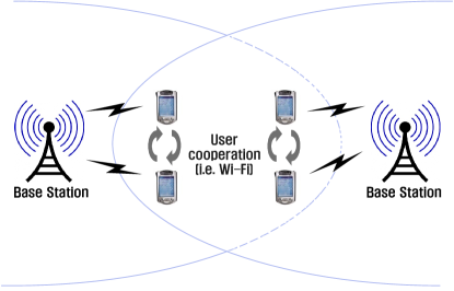
In this section, we describe a system model for the two-cell MIMO-IFBC as shown in Fig. 1. The system of the two-cell MIMO-IFBC consists of two BSs with antennas per BS and users with receive antennas per user in each cell. It is assumed that users in each cell can cooperate to share their CSI using the Wi-Fi links which offers wireless connectivity on a peer-to-peer basis without the assistance of wired network. This assumption is valid in the case where cooperating users are located in a local area, such as in a campus or a library. For notation convenience, we refer to the -th user in the -th cell as user . We assume each BS tries to convey one data stream per user to its corresponding users.
II-A BS-User Links for Cellular Networks
The received signal at the user is represented as
| (2) |
where denotes the transmitted symbol for the -th user in the -th cell, satisfying an average power constraint, , and is the linear beamforming vector for carrying the symbol, , with unit norm constraint, i.e., . In (2), is the additive white Gaussian noise (AWGN) vector with variance per entry at the -th user in the -th cell, and is the channel matrix from the BS to the user . We define as the cell index which is not equal to , and . The channel matrices for and are generated so that each entry of the matrix is independent and identically distributed (i.i.d.) according to , and it is assumed that each channel obeys a frequency flat block-fading channel model. We also suppose that perfect channel state information (CSI) is available at all users. Each user decodes the desired signals coming from its corresponding BS by multiplying the receive beamforming vector, and the signal at the user after receiver combining is given by
| (3) | |||||
where denotes the receive beamforming vector for the user , whose size is , and is the effective noise vector, each entry of which is distributed as . The notation means the conjugate transpose operator.
II-B User-Cooperative Links for Wi-Fi Networks
The user-cooperative links are connected by the Wi-Fi networks in an ad hoc mode [3] without any adverse impacts or interference caused by the cellular network. In this paper, these links are assumed to be noiseless with achievable rates which are enough to share CSI of interfering channels among cooperating users in each one cell.
II-C Degrees of Freedom (DoF)
For the given set of beamforming vectors, and , where and , the achievable rate at the user supported by the BS is written as given in equation (1).
We define the rate region to be the set of all rates that can be achieved by using the transmit and receive beamforming vectors under individual power constraints, which is given by
| (4) |
Further, we define the degrees of freedom which is the pre-log factor of the sum rate. This is one of the key metrics for assessing the performance of the system in the multiple antenna systems at the high SNR regime, which is defined as
| (5) |
where
denotes the sum rate at signal-to-noise ratio
.
III New IA scheme through user cooperation
In this section, we introduce a new IA scheme which mitigates both ICI and IUI simultaneously in the two-cell MIMO-IFBC with help of user cooperation, and investigate the benefits of user cooperation compared with existing schemes in terms of DoF and the amount of channel feedback.
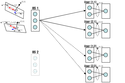
III-A Motivating example for
To explain our scheme and its benefits clearly, we start with a simple case of as shown in Fig. 2. The BS wants to deliver two symbols, and , to the user and user using the transmit beamforming vectors and , respectively. In general, for given receive beamforming vectors, the minimum number of transmit antennas is 4 so that the transmit beamforming vectors cancel out all ICI and IUI. For example, in order to transmit the symbol without causing any interference to the other users, the beamforming vector should satisfy the following condition,
| (6) |
where denotes an orthonormal basis for the null space of a matrix. However, our proposed scheme can remove both ICI and IUI with 3 transmit antennas by performing ICI channel alignment. In the following four steps, we present our transmit and receive beamfoming design method enabling the ICI channel alignment through user cooperation without the need of global CSI.
Step 1: Sharing interfering channels among users
In order to share CSI between co-located cell-edge users, user terminals perform user cooperation using the Wi-Fi network in ad-hoc mode. To be specific, the user and the user exchange CSI of interfering channels to cooperatively design receive beamforming vectors.
Step 2: Designing the receive beamforming vectors
By using CSI of interfering channels acquired in the step 1, the user and user design the receive beamforming vectors and , so that the effective ICI channels from the BS 1 are aligned with each other, which is
| (7) |
where denotes the space spanned by the column vectors of a matrix.
We can find out the intersection subspace satisfying the condition (7) above by solving the following matrix equation,
| (13) |
where implies the direction of aligned effective interference channels from the BS to the user and user after applying the receiver beamforming vectors. Since the size of the matrix is , it has one dimensional null space. Therefore, the receive beamforming vectors for ICI channel alignment can be obtained explicitly with probability one.
Step 3: Feedback the effective channels to the BS
Each user feeds back equivalent channels after applying the receive beamforming vectors determined in the step 2 instead of channels itself through uplink feedback channels for the cellular networks to its corresponding BS. To be specific, the user is required to feed back both the effective serving and interfering channel vectors after applying the receive beamforming vectors, i.e., and .
Step 4: Choosing the transmit beamforming vectors
Since the effective ICI channels are aligned with each other, the BS 1 can consider two different ICI channel vectors as a one ICI channel vector which spans one dimensional subspace as shown in Fig. 2. Therefore, if the beamforming vectors and are designed with the effective channel information in the step 3 as
| (14) |
the BS 1 can send the symbols and to the user and user without any interferences, respectively.
III-B General case for multiple user
We now generalize the proposed IA scheme explained in previous section for multiple cell-edge users in each cell, . The following theorem is the main result of this paper.
Theorem 1: For the two-cell MIMO-IFBC where each BS supports users simultaneously, we can achieve degrees of freedom if the BS and user have and antennas, respectively.
Proof ) The achievability proof is provided by using an extension of the interference alignment scheme presented in previous subsection. To prove Theorem 1, we show that , is achieved when the numbers of transmit antennas and receive antennas are equal to and , respectively. To be able to decode a single stream at each user, the interferences coming from -th cell and -th cell should be aligned within no more than dimensional in order to obtain 1 interference free dimension from a -dimensional received signal vector. Without loss of generality, the transmit and receive beamforming vectors to mitigate both ICI and IUI simultaneously in the two-cell MIMO-IFBC can be designed as in equation (10) on the top of the next page.
| (15) |
| Schemes | Achievable | Channel feedback | Channel feedback | Total channel feedback† |
|---|---|---|---|---|
| degrees of freedom | for serving cell† | for interfering cell† | ||
| CZF [5] | ||||
| Subspace IA [11] | 0 | |||
| Proposed IA | ||||
| †The number of complex valued elements needed for channel feedback. | ||||
To reduce the required number of transmit antenna satisfying (10), we design the receive beamforming vectors so that effective inter-cell interference channels (IFC) are aligned within one dimensional space through the user cooperation to share CSI of interfering channels among all users in each cell. This conditions can be rewritten into more restrict conditions as follows:
| (16) |
The equation (11) can be represented in a matrix form, i.e.,
| (17) |
From equation (12), we can find the receive beamforming vectors to satisfy (11) by equivalently calculating the null space of . It is noted that there exists a vector in the null space of only when the number of columns of is greater than the number of rows of by the number of data streams for each user, , , i.e.,
| (18) |
Moreover, if the all effective ICI channels after applying receiver beamforming vectors are aligned within a single dimension of each receiver, the minimum number of transmit antennas to remove both IUI and ICI simultaneously is necessary, i.e.,
| (19) |
These conditions (13)-(14) now take simpler forms and can be expressed as
| (20) |
To satisfy the condition (15), it is necessary to equip the numbers of transmit antennas and receive antennas at each BS and user at a minimum, respectively, which completes the proof.
III-C Discussions
In this subsection, we compare the achievable degrees of freedom and the feedback overhead for different schemes. For comparison, we focus on the system configuration of .
-
•
Degrees of Freedom: In this case, the coordinated ZF scheme proposed by [5] and the subspace IA scheme in [11] can attain and degrees of freedom, respectively, while our proposing scheme is able to achieve degrees of freedom. Interestingly, in the case of , our proposed scheme attains the optimal degrees of freedom [18], which coincides with the trivial outer bound in [9]. The reason for the increase of degrees of freedom comes from that the interference alignment can utilize the signal space efficiently rather than the coordinated ZF scheme and the subspace IA do.
-
•
Feedback Overhead: To compare the feedback overhead, we measure the amount of two different types of feedback information. The proposed IA scheme needs much smaller amount of channel feedback compared to the conventional schemes with global CSI available at the BS, i.e., [5] and [6], in the cellular networks at the expense of the user cooperation through the Wi-Fi link. For instance, the user is required to feed back the full CSI, i.e., and for performing the conventional schemes, while the proposed IA scheme only requires the effective channel vectors after applying the receive beamforming vectors explained in (8), i.e., and . Especially, the effective interference channel vectors after ICI channel alignment for all users in the same cell are perfectly aligned along with a same direction, and this implies that only one user in each cell is enough to feed back the aligned interfering channel direction, i.e., . Therefore, we can significantly diminish the total required amount of feedback information for interfering cell via uplink resources in the cellular networks with the help of user cooperation.
In conclusion, our proposed scheme has much better performance than the existing schemes while it requires much smaller amount of feedback overhead than existing schemes under full CSI assumption. The discussions above are summarized in Table I.
IV Simulation results
Through simulation results, we first demonstrate that our proposed scheme attains the degrees of freedom analytically derived in section III and access the ergodic sum rate performance of the proposed interference alignment scheme. Throughout the simulations, the transmit power of all BSs is fixed at , and noise variance of all receive antennas at a user is assumed to be the same, i.e., . The simulation results are illustrated with respect to the ratio of the total transmit power to noise variance at each receive antenna in dB scale (SNR=).
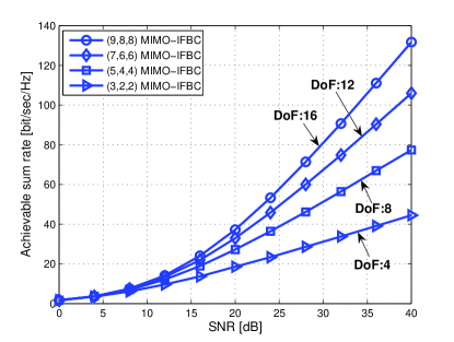
Fig. 3 illustrates the sum rate performance of the proposed interference alignment scheme according to various system configuration as a function of the SNR. As shown in this figure, the sum rate increases linearly with the slope of 4, 8, 12, and 16 in , , , and MIMO-IFBCs, respectively. It confirms that the sum rate performances exactly coincide with the DoF of which is analytically derived in Section III.
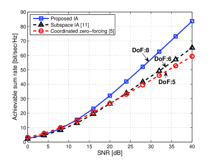
To show superiority of the proposed IA scheme, we compare the sum rate performance of the proposed scheme with those of existing coordinated beamforming schemes in the MIMO-IFBC. As presented in Fig. 4, the proposed interference alignment method exhibits superior performance to the existing schemes described above. We also observe that the sum rate of the proposed scheme grows linearly with the slope of 8 while those of the existing schemes increase linearly with the slope of 5 and 6. From these results, we can see that the efficient utilization of the signal space leads the performance enhancement by increasing degrees of freedom.
V Conclusion
In the two-cell MIMO-IFBC, we proposed a novel cross network interference alignment algorithm exploiting benefits of the heterogeneous networks consisting of Wi-Fi systems and cellular systems. By exchanging CSI among users through Wi-Fi links, our proposed algorithm does not cause any interference to cellular links as well as significantly reduces the amount of channel feedback via cellular links. The algorithm also performs a joint design of transmit and receive beamforming vectors using the shared CSI. Furthermore, our algorithm employs intersection subspace property of the vector space to utilize signal spaces efficiently, thereby achieving higher DoF gains compared to the existing techniques. Further work will consider: i) user cooperation with limited channel feedback, and ii) the extension to the MIMO-IFBC with more than two cells.
References
- [1] 3GPP TR 36.814 V9.0.0, “Further advancements for E-UTRA physical layer aspects (Release 9),” Oct. 2006.
- [2] IEEE C802.16-10/0009, “Future wireless broadband networks: challenges and possibilities,” Jan. 2010.
- [3] Wi-Fi alliance, “Wi-Fi Peer-to-Peer (P2P) technical specification: draft versioxn 0.2,” March 2009.
- [4] S.-H. Park and I. Lee, “Degrees of freedom and sum rate maximization for two mutually interfering broadcast channels,” Proc. IEEE Int. Conf. Commun. (ICC), Dresden, Germany, June 2009.
- [5] J. Kim, S.-H. Park, H. Sung, and I. Lee, “Sum rate analysis of two-cell MIMO broadcast channels: spatial multiplexing gain,” Proc. IEEE Int. Conf. Commun. (ICC), Cape Town, South Africa, May 2010.
- [6] V. R. Cadambe and S. Jafar, “Interference alignment and degrees of freedom of the -User interference channel,” IEEE Trans. Inf. Theory, vol. 54, pp. 3425-3441, Aug. 2008.
- [7] K. S. Gomadam, V. R. Cadambe, and S. A. Jafar, “Approaching the capacity of wireless networks through distributed interference alignment,” e-print, arXiv:0803.3816.
- [8] M.A. Maddah-Ali, A.S. Motahari, and A.K. Khandani, “Communication over MIMO X channels: interference alignment, decomposition, and Performance analysis,” IEEE Trans. Inf. Theory, vol. 54, pp. 3457-3470, Aug. 2008.
- [9] S. Jafar and M. Fakhereddin, “Degrees of freedom for the MIMO interference channel,” IEEE Trans. Inf. Theory, vol. 53, No. 7, pp. 2637-2642, July 2007.
- [10] C. Suh and D. Tse, “Interference alignment for cellular networks,” Proc. Communications, Control and Computing, 46th Annual Allerton Conference, Illinois, USA, Sept. 2008.
- [11] C. Suh, M. Ho, and D. Tse, “Downlink interference alignment,” e-print, arXiv:1003.3707.
- [12] R. Dabora and S. D. Servetto, “Multi-user MISO broadcast channel with user-cooperating decoder,” IEEE Trans. Inf. Theory, vol. 52, pp. 5438-5454, Dec. 2006.
- [13] H. Kwon and J. M. Cioffi, “Multi-user MISO broadcast channel with user-cooperating decoder,” Proc. IEEE Veh. Tech. Conf. (VTC), Calgary, Canada, Sept. 2008.
- [14] A. Høst-Madsen, “Capacity bounds for cooperative diversity,” IEEE Trans. Inf. Theory, vol. 52, pp. 1522-1544, Apr. 2006.
- [15] V. Prabhakaran and P. Viswanath, “Interference channels with destination cooperation,” e-print, arXiv:0907.2702.
- [16] I.-H. Wang and D.N.C. Tse, “Interference mitigation through limited receiver cooperation,” e-print, arXiv:0911.2053v1.
- [17] W. Yu and L. Zhou, “Gaussian Z-interference channel with a relay link: Achievability region and asymptotic sum capacity,” e-print, arXiv:1006.5087v1.
- [18] W. Shin, N. Lee, J.-B. Lim, C. Shin, and K. Jang, “On the design of interference alignment scheme for two-cell MIMO interfering broadcast channels,” accepted to IEEE Trans. Wireless Comm., June 2010