Plasmonic space folding: focussing surface plasmons via negative refraction in complementary media
Muamer Kadic, Sebastien Guenneau, Stefan Enoch
Institut Fresnel, CNRS, Aix-Marseille Université,
Campus universitaire de Saint-Jérôme, 13013 Marseille, France
sebastien.guenneau@fresnel.fr
S. Anantha Ramakrishna
Department of Physics, Indian Institute of Technology, Kanpur 208016, India
Résumé
We extend designs of perfect lenses to the focussing of surface plasmon polaritons (SPPs) propagating at the interface between two anisotropic media of opposite permittivity sign. We identify the role played by the components of anisotropic and heterogeneous tensors of permittivity and permeability, deduced from a coordinate transformation, in the dispersion relation governing propagation of SPPs. We illustrate our theory with three-dimensional finite element computations for focussing of SPPs by perfect flat and cylindrical lenses.
Références
- [1] V.G. Veselago, “The electrodynamics of substances with simultaneously negative values of [permittivity] and [permeability],” Soviet Physics Uspekhi 10(4), 509-514 (1968)
- [2] J.B. Pendry, “Negative Refraction Makes a Perfect Lens,” Physical Review Letters 85 (18), 3966 (2000)
- [3] S.A. Ramakrishna and T.M. Grzegorczyk, “Physics and Applications of Negative Refractive Index Materials,” CRC Press, 2008
- [4] J.B. Pendry, D. Schurig, and D.R. Smith, “Controlling Electromagnetic Fields,” Science, 312, 1780 (2006).
- [5] U. Leonhardt, “Optical Conformal Mapping,” Science 312, 1777 (2006).
- [6] F. Zolla, S. Guenneau, A. Nicolet, and J.B. Pendry, “Electromagnetic analysis of cylindrical invisibility cloaks and the mirage effect”, Opt. Lett. 32, 1069-1071 (2007).
- [7] J.B. Pendry and S. Anantha Ramakrishna, Near field lenses in two dimensions, J. Phys.: Condens. Matter 14, 8463-8479 (2002) cond-mat/0206567.
- [8] J.B. Pendry and S. Anantha Ramakrishna, Focussing light with negative refractive index, J. Phys.: Condens. Matter 15 6345 (2003). cond-mat/0310327
- [9] U. Leonhardt and T. G. Philbin, “Transformation Optics and the Geometry of Light,” Prog. Opt. 53, 69-152 (2009).
- [10] S. Guenneau and S.A. Ramakrishna, “Negative refractive index, perfect lenses and checkerboards: Trapping and imaging effects in folded optical spaces” Comptes Rendus Physique 10 (5), 352-378 (2009).
- [11] N. H. Shen, S. Foteinopoulou, M. Kafesaki, Th. Koschny, E. Ozbay, E. N. Economou, and C. M. Soukoulis, “Compact planar far-field superlens based on anisotropic left-handed metamaterials,” Phys. Rev. B 80, 115123 (2009).
- [12] D. Maystre and S. Enoch, “Perfect lenses made with left handed materials: Alice’s mirror,” J. Opt. Soc. Am. A 21, 122-131 (2004).
- [13] J.B. Pendry, “Perfect cylindrical lenses,” Opt. Express 11, 755- 760 (2003).
- [14] N.A. Nicorovici, R.C. McPhedran and G.W. Milton,“Optical and dielectric properties of partially resonant composites,” Phys. Rev. B 49, 8479-8482 (1994).
- [15] S. Guenneau, B. Gralak and J.B. Pendry, “Perfect corner reflector,” Optics Letters 30 (10), 1204-1206 (2005).
- [16] S. Guenneau, A.C. Vutha and S.A. Ramakrishna, Negative refraction in 2D checkerboards related by mirror anti-symmetry and 3D corner lenses New Journal of Physics 7, 164 (2005).
- [17] S. Chakrabarti, S.A. Ramakrishna and S. Guenneau, “Finite checkerboards of dissipative negative refractive index,” Optics Express 14 (26), 12950-12957 (2006).
- [18] S. Maier, Plasmonics: Fundamentals and Applications, Springer Verlag, 2007
- [19] A.V. Zayats, I.I. Smolyaninov, A.A. Maradudin, “Nano-optics of surface plasmon polaritons,” Phys. Rep. 408, 131-314 (2005).
- [20] T. W. Ebbesen, H. J. Lezec, H. F. Ghaemi, T. Thio, P. A. Woff, “Extraordinary optical transmission through sub-wavelength hole arrays,” Nature 391, 667 (1998).
- [21] J.B. Pendry, L. Martin-Moreno and F.J. Garcia-Vidal, “Mimicking surface plasmons with structured surfaces,” Science 305, 847 (2004).
- [22] A. Alu and N. Engheta, “Achieving transparency with plasmonic and metamaterial coatings,” Phys. Rev. E 72 016623 (2005).
- [23] F.J. Garcia de Abajo, G. Gomez-Santos, L.A. Blanco, A.G. Borisov and S.V. Shabanov, “Tunneling Mechanism of Light Transmission through Metallic Films,” Phys. Rev. Lett. 95, 067403 (2005).
- [24] B. Baumeier, T.A. Leskova and A.A. Maradudin, “Cloaking from surface plasmon polaritons by a circular array of point scatterers,” Phys. Rev. Lett. 103, 246809 (2009).
- [25] V.M. Agranovich, Y.R. Shen, R.H. Baughman, and A.A. Zakhidov, Optical bulk and surface waves with negative refraction, Journal of Luminescence 110, 167-173 (2004).
- [26] M. Kadic, S. Guenneau and S. Enoch, “Transformational plasmonics: cloak, concentrator and rotator for SPPs,” Opt. Express 18(11), 12027-12032 (2010).
- [27] P.A. Huidobro, M.L. Nesterov, L. Martin-Moreno and F.J. Garca-Vidal, “Transformation Optics for Plasmonics,” Nano Lett. 10 (6), 1985-1990 (2010).
- [28] Y. Liu, T. Zentgraf, G. Bartal and X. Zhang, “Transformational Plasmon Optics,” Nano Lett. 10 (6) 1991-1997 (2010).
- [29] J. Renger, M. Kadic, G. Dupont, S. Acimovic, S. Guenneau, R. Quidant and S. Enoch, “Hidden Progress: Broadband plasmonic invisibility,” Opt. Express 18 (15), 15757-15768 (2010).
1 Introduction
Focusing light using negative refraction is an emerging subject mixing fascinating and elusive features. It is now well known that one can reverse the flow of light with negative refractive index materials, within which light takes the “wrong” turn in accordance with inverted Snell-Descartes laws of refraction [1, 2, 3]. However, there has been a growing interest in a better control of light through transformational optics, following the recent proposals by Pendry et al. [4] and Leonhardt [5]. The former seminal paper demonstrates the possibility of designing a cloak that renders any object inside it invisible to electromagnetic radiation (using the covariant structure of Maxwell’s equations), while the latter concentrates on the ray optics limit (using conformal mappings in the complex plane). In both cases, the cloak consists of a meta-material whose physical properties (permittivity and permeability) are spatially varying as well as anisotropic.
Importantly, if one considers a point source located inside the cloak, it appears to radiate from a shifted location: Cloaking is nothing but a mirage effect [6]. If one adopts this viewpoint, complementary media [7, 8] within which focussing effects via negative refraction occur can be designed using geometric transforms by mapping the image plane back onto the source plane [9, 10]. Such lenses were coined as Alice mirrors in [12] since they exhibit certain anti-symmetric features. These make also possible perfect and poor man’s cylindrical lenses [13, 14], as well as generalized corner and checkerboard lenses [8, 15, 16, 17].
However, there are other types of electromagnetic waves well worth controlling such as surface plasmon polaritons (SPPs) that allow for fascinating applications in the emerging field of nano-optics [19, 18]. Back in 1998, Ebbesen et al. established that resonant excitation of SPPs on a metal film perforated at subwavelength periodicities leads to unusually high transmission coefficients [20]. Pendry, Martin-Moreno and Garcia-Vidal further showed in 2004 that one can manipulate SPPs by structuring perfectly conducting surfaces in a periodic manner [21]. Other plasmonic metamaterials include plasmonic shells with a suitable out-of-phase polarizability in order to compensate the scattering from the knowledge of the electromagnetic parameters of the object to hide, and external cloaking, whereby a plasmonic resonance cancels the external field at the location of a set of electric dipoles [14, 22, 23, 24].
In the present paper, we extend the design of transformation based perfect lens to the focussing of surface plasmon polaritons (SPPs). The field of plasmonics has matured to the point where an introduction to the optical properties of metals and sometimes even surface plasmons is included in many standard texts in solid-state physics and optics, with a state of the art on meta-surfaces available in [3, 18]. Interestingly, Agranovich et al. have shown in 2004 that one can obtain negative refraction for exciton-plasmon waves in organic and gyrotropic material using a surface transition layer [25].
Our main contribution here is that we explain how one can manipulate SPPs in such a way that the electromagnetic space where they live is folded back onto itself, so that we can extend the proposal of Pendry and Ramakrishna to build generalized lenses using the original concept of complementary media [7, 8] to the area of plasmonic waves. This allows for instance the design of perfect corners, corner lenses and the like [8, 15, 16, 17], using transformational plasmonics tools [26, 29, 28, 27]. Importantly, we also perform full wave computations to exemplify the imaging effects of SPPs through negative refraction in a novel class of generalised plasmonic lenses.
2 Transformational plasmonics and generalized perfect lenses in Cartesian coordinates for SPPs
Let us consider two semi-infinite regions separated by a plane interface at . The upper region () is filled with air i.e. with relative permittivity (resp. relative permeability ), while the lower region () is filled with a Drude metal i.e. with relative permittivity
| (1) |
(resp. relative permeability ): here, some gold with the plasma frequency ( THz) and characteristic collision frequency ( THz). We would like to map these two isotropic homogeneous media on two metamaterials described by anisotropic heterogeneous matrices of permittivity and permeability given by [6]
| (2) |
where is the transformation matrix constructed using the Jacobian associated with the change of coordinates. Let us emphasize here that in our numerical implementation, we make use of finite edge elements that are nothing but discrete Whitney differential forms, and behave nicely under pull-back transforms. Thus, in what follows, we always map the destination domain onto the original one (so we consider the inverse transforms).
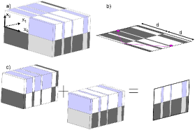
The original perfect lens presupposed a slab of material with = -1 and = -1. Let us now derive the result using the powerful tool of transformational plasmonics [26]. In order to design generalized lenses for surface plasmon polaritons, we want to fold the plasmonic space back onto itself, and this leads to negative coefficients within the permittivity and permeability matrices. The coordinate transformation is given by
where is the thickness of the generalized lens.
The above coordinate transform leads to the identity for the transformation matrix outside the lens, whereas inside the lens i.e. for , which flips the sign of , so that the material properties differ from free space only for points along the direction.
The above analysis demonstrates that SPP focussing will always occur irrespective of the medium in which the lens is embedded. This is true for any medium which is mirror antisymmetric about a vertical plane. In the plasmonic case, we can define two complementary media above the metal surface and two complementary media within the metal as
Case corresponds to the top region: , while case corresponds to the bottom region , with and as in (1),
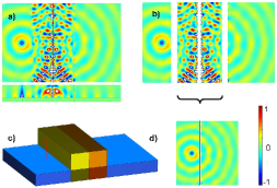
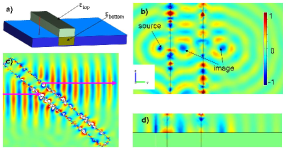
We report in Figure 2 some finite element computations showing focussing of a SPP at a wavelength of nm for two such complementary media i.e. a checkerboard lens for the special case . The cancellation of plasmonic space is noted. We further show in Figure 3 a focussing effect through a plasmonic flat lens with . The source and the perfect images indeed satisfy the inverted Snell-Descartes laws of negative refraction, as shown for a SPP beam incident upon the lens at an angle of 45 degrees.
However, in the case of anisotropic and , the transformed media are now characterized in the region by
| (3) |
We note that there is no change in the impedance of the media, since the permittivity and permeability undergo the same geometric transformation: the perfect lens is impedance-matched with its surrounding medium (air, say) so that no reflection will occur at its interfaces.
Then the resulting complementary medium (see Figure 1) is given by
| (4) |
where and are as in (1), and for and for . This is a generalization to transformational plasmonics of the result first derived in [8] and retrieved again using group theory (symmetries of Maxwell’s equations) in [16]. The entries in and can also be spatially varying along and . This covers the case of perfect corner reflectors of -fold skew-symmetry and we are therefore ensured of the cancellation of the plasmonic path. It is worth noting that the generalized lens theorem was also applied to infinite checkerboards of skew-symmetry in [16, 17].
We now extend the dispersion relation for a surface plasmon at the interface between a transformed medium and a transformed metal [26] to the case where we have four media described by diagonal tensors of relative permittivity and permeability: and with when and when , see Figure 1 (a), The SPP propagating at the metal surface has a wavenumber satisfying:
| (5) |
where denotes the transformed medium and its Drude metal counterpart. This formula also characterizes the wavenumber of an SPP propagating at a multi-layered metal surface, whereby the number of complementary regions is only constrained by the overall propagation length of the SPP.
Following the work by Shen et al. [11] on two-dimensional anisotropic perfect lenses, we report in Figure 4 some computations for an SPP (Gaussian beam) incident from the left on such a lens in the three-dimensional transformational plasmonic setting. Above the metal interface, the transformed medium is described by and for the bottom layer, the transformed metal is described by: and which is a particular case of (4). In panels (b) and (d) of Figure 4, we place a line source within the slab lens (shown by point in panel (a)), and we observe two perfect images on either sides of the anisotropic lens, in accordance with the inverted Snell-Descartes laws of refraction. We note that on the vertical sides of this lens, the following condition is met:
| (6) |
where describe the ambient medium above the surface (air) and is as in (1) and . Hence, the slab lens is perfectly matched to the surrounding medium.
We numerically check this fact by sending a Gaussian SPP beam with a waste of nanometers on this less than usual lens. The wavefront shrinks within the lens, but forward and backward scatterings do not sense the presence of the lens: the lens is indeed invisible for any SPP propagating on the metal surface.
3 Transformational plasmonics and generalized perfect lenses in cylindrical coordinates for SPPs
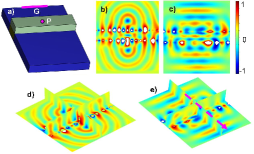
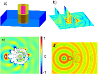
Building on the previous perfect lens theory, we can use conformal transformations to bend the shape of the perfect lens into other geometries such as two concentric cylinders, see Figure 5(a). The objective is to follow Pendry’s proposal of a magnifying glass, and for this purpose the lens must be curved. The conformal transformation , where is known to preserve the solutions of Laplace’s equation and leaves the values of and unchanged. However, when one departs from the static case, the previous geometric transform leads to anisotropic heterogeneous permittivity and permeability tensors.
Following the same algorithm as in the previous section we find that a possible design for a cylindrical perfect lens for SPPs (avoiding spatially varying media outside the lens) is given by
| (7) |
with for , for , and and as in (1).
We show in panels (b) and (d) of Figure 5 some 3D finite element computations for a SPP line source at a wavelength of nm, located inside the central region of the cylindrical lens. We also depict in panel (c) a 2D numerical simulation for comparison with the case of transverse electric waves (whereby ). We note that in such a configuration, the image is magnified.
4 Conclusion
In conclusion, we have studied analytically and numerically the extension of optical space folding to the area of plasmonics. This requires anisotropic heterogeneous complementary media deduced from geometric transformations. Focusing SPP through a markedly enhanced control of their wave trajectories has been demonstrated. Importantly, our analysis applies mutatis mutandis for a s-polarized SPP (interchanging the roles of permittivity and permeability). For illustrative purpose, checkerboard and cylindrical designs of SPP lenses have been proposed and implemented in the finite element commercial package COMSOL.
The authors are grateful for insightful comments by Mr G. Dupont and Prof. R. Quidant. MK acknowledges funding from the French ministry of Higher-Education and Research. SG, SAR and SE are thankful for funding to the Indo-French Centre for the Promotion of Advanced Research, New Delhi under project no. IFCPAR / 3804 -2.