Magnetoelectric coupling at the interface of BiFeO3/La0.7Sr0.3MnO3 multilayers
Abstract
Electric-field controlled exchange bias in a heterostructure composed of the ferromagnetic manganite La0.7Sr0.3MO3 and the ferroelectric antiferromagnetic BiFeO3 has recently been demonstrated experimentally. By means of a microscopic model Hamiltonian we provide a possible explanation of the origin of this magnetoelectric coupling. We find, in agreement with experimental results, a net ferromagnetic moment at the BiFeO3 interface. The induced ferromagnetic moment is the result of the competition between the -electrons double exchange and the -spins antiferromagnetic superexchange that dominate in bulk BiFeO3. The balance of these simultaneous ferromagnetic and antiferromagnetic tendencies is strongly affected by the interfacial electronic charge density which, in turn, can be controlled by the BiFeO3 ferroelectric polarization.
pacs:
75.47.Gk, 75.10.-b, 75.30.Kz, 75.50.EeIntroduction. The quest for efficient electric field control of magnetic properties has encouraged research on materials with a strong coupling between the magnetic and dielectric degrees of freedom mathurNat06 . Such a control would find applications in magnetic field storage and sensors, constituting a major step forward in the field of spintronics. However, so far no bulk material seems to possess the required characteristics, including working near room temperature. For these reasons, the field effect device presented in Ref. BFO_LSMO_NM signals a new route review-multiferroics to achieving those goals by growing a few nanometers thick layer of La0.7Sr0.3MnO3 (LSMO), a ferromagnetic (FM) metal, on an antiferromagnetic (AFM) and ferroelectric (FE) material, BiFeO3 (BFO) BFO_LSMO_NM ; BFO_LSMO_PRL . These experiments provided evidence for an induced FM moment in BFO at the interface. This magnetic moment is strongly affected by the BFO polarization, which results in an electric field control of the LSMO exchange bias (EB), and concomitant control of the LSMO magnetization.
Magnetic moments induced at the interface of perovskite-based oxide materials have been previously reported. For example, a net magnetic moment was induced in an AFM manganite when grown in a multilayer with a FM manganite niebieskikwiat07 ; sefroui10 , at the interface of a superconducting cuprate with La0.67Ca0.33MO3 Chakhalian , and at LSMO/SrTiO3 interfaces Barriocanal_Ti . Electronic energy loss measurements indicate that a charge redistribution takes place Chakhalian ; Barriocanal_Ti . Theoretically, the origin of the induced magnetic moment in niebieskikwiat07 was explained in terms of charge transfer and a double exchange (DE) type interaction TMR . Charge transfer, together with orbital reconstruction, is also believed to play a role at cuprate/La0.67Ca0.33MO3 interfaces Chakhalian . In BFO_LSMO_PRL ; Okamoto_10 the BFO induced FM moment in LSMO/BFO heterostructures was attributed to Fe-Mn hybridization, which is associated with charge transfer. The recently observed coupling of the EB with an induced magnetization near the interface, simultaneously controlled by the FE polarization BFO_LSMO_NM ; BFO_LSMO_PRL , defines a new complex phenomenon that requires a better theoretical understanding Suhai_EB .
In this letter, a microscopic model for the transition metal -electrons is shown to explain the main properties of the BFO/LSMO interface. Within this model, the magnetic moments of the Fe ions develop a net FM moment close to the interface as a consequence of both charge and orbital redistribution, while they remain AFM ordered far from the interface. Interestingly, the direction and magnitude of the BFO moment with respect to the magnetization of the LSMO layer depend on the charge density at the interface. Small changes in the charge density due to the switching of the FE polarization in BFO produces large modifications in the direction of the magnetic moment induced in the Fe ions. This leads to the experimentally observed EB BFO_LSMO_NM . Our scenario is qualitatively different from that proposed in BFO_LSMO_PRL , which is based on the first LSMO layer, and that of Suhai_EB , which requires a spin-orbit coupling.
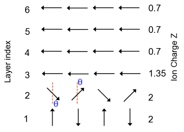
Model. Fig. 1 sketches the supercell used in our calculations. Bulk LSMO (BFO) is in a FM (G-type AFM) state. A possible magnetic reconstruction near the interface is also indicated. Departures from the cubic perovskite lattice, as induced by strain and ferroelastic effects, are ignored for simplicity. The -axis size ( layers for LSMO and for BFO) is selected such that bulk behavior is recovered at the center of the composing films.
Magnetism in the heterostructure arises from the transition metal electrons. In manganites, the three electrons are localized and are approximated by a single classical spin. AFM superexchange with neighboring sites is introduced via a Heisenberg interaction Dagotto-review . The quantum itinerant electrons are described by the DE model in the infinite Hund’s coupling limit. Several aspects of the rich physics of bulk Dagotto-review ; MatToday ; Sen_10 ; breyPRL04 and heterostructured manganites Brey_PS ; TMR ; dong08 ; rong09 have been successfully addressed within this approach. However, model Hamiltonian approaches have not been used before for BFO.
To properly consider the effects of charge leakage and orbital hybridization at the interface Okamoto_10 , the electrons of both BFO and LSMO must be treated on equal footing. The model is:
| (1) | |||||
Here, Si represents the spin at site , located either at the LSMO or the BFO side of the heterostructure, while is the AFM superexchange parameter. creates an electron on an orbital centered at the transition metal site with symmetry: , = , . The hopping term is modulated by the DE factor Dagotto-review that depends on the angle between Si and Sj such that it is maximum for parallel alignment of spins at neighboring sites and zero for antiparallel alignment. Hopping also depends on the overlap between the and orbitals along the direction through the geometric factor Dagotto-review . In principle, the hopping parameters should depend on the material, and would be affected by lattice distortions near the interface. We simplify the calculation by assuming a uniform hopping parameter for the whole heterostructure (=) ( is the energy unit). The superexchange coupling is more sensitive to changes in lattice constants, hence each material will be characterized by a different .
In general, the DE term in Eq.(1) favors FM configurations that optimize the kinetic energy, while the superexchange term favors AFM phases. The third term contains the different contributions to the site potential. Long range Coulomb interactions are essential to control charge transfer across the interface. This is included in the Hartree approximation by setting
| (2) |
The Coulomb interaction strength is regulated by the parameter , here assumed equal to lin06 ; TMR . For each - plane, Z as illustrated in Fig. 1 is considered, and the approximation is made that the background consists of point charges that occupy the transition metal sites. Z=2 for BFO, while Z=0.7 for LSMO. An interfacial layer is considered with an intermediate value of Z, to account for possible diffusions and different chemical environments of the transition metal ions at the interface. includes the effect of the band offset between BFO and LSMO , and the surface charge density due to ferroelectricity . The band offset is difficult to estimate, though expected to be small. From BFO electronic affinity Yang10 and LSMO work functions LSMO_wf , we estimate . However, is here treated as an adjustable parameter: it is first set to zero and the results are then checked against moderate changes in its value. The chemical potential is chosen so that the overall system remains charge neutral.
Several approximations are implicit in Eq.(1). While the intraorbital Hubbard interaction is effectively infinite due to the infinite Hund’s coupling implicit in DE, the interorbital might be important. However, it has been checked that introducing a moderate =2 at the mean-field level does not significantly affect the results. The coupling to Jahn-Teller lattice modes is not included either, but it is widely accepted that they do not play an important role in LSMO or BFO at any of the interfacial fillings of the bands. For each set of parameters and different spin configurations, Eq.(1) was solved by exact diagonalization. Periodic boundary conditions are used, with a 551 mesh in reciprocal space.
Results. Our first important result is sketched in Fig. 1. While LSMO remains FM, and most of BFO remains in the G-AFM state, a magnetic reconstruction takes place in the last atomic layer of BFO. The perpendicular orientation of the spins in bulk BFO (layer 1) relative to LSMO gives lower energy than a parallel orientation. The magnetic state in the last BFO layer can be characterized by a single angle , defined in Fig. 1, which determines the magnetization of BFO close to the interface, . For =, the last layer of BFO is FM but antiparallel to the LSMO magnetization, thus =; for =, the last layer of BFO is FM and parallel to the LSMO magnetization, =; and for =, there is no net magnetization in BFO. Regardless of the ground state value of , the main magnetic reconstruction is confined to the BFO outmost layer, since spin canting at the LSMO interfacial atomic layer is small. These results are remarkably independent of details, such as whether there is an interfacial layer with intermediate background charge. It also holds for several values of , as long as they are reasonable (for the proper bulk phase diagram: ; ). (between layers 2 and 3) is expected to be some average of and . For simplicity, we use == and .
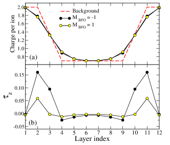
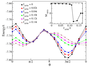
Fig. 2 illustrates the energy as a function of for different values of . At small , the energy is minimized at =: the BFO interfacial layer is FM and parallel to the metallic LSMO and DE dominates. As increases, the minimum near moves toward . In addition, the minimum near decreases in energy and eventually has the lowest energy. In this case the last layer of BFO is FM and antiparallel to the LSMO magnetization. This trends are summarized in the inset of Fig. 2 where the magnetization induced in the last layer of BFO is plotted as a function of . The magnetization rotation (from = to ) occurs at and there is some small canting for . For , the AFM coupling is stronger than the DE and the canting angle is zero, namely, the interfacial BFO layer is AFM as in bulk. Several results obtained in the simplified discussion presented here, such as Fig. 2 and others based on the simple assumption that the interfacial behavior is characterized by a single angle , were also confirmed numerically using 448 clusters, the Poisson equation, and a minimization algorithm for the classical spins Broyden .
The observed charge redistribution and orbital reconstruction confirm the importance of the DE mechanism. Fig. 3 shows the charge and orbital polarization for two values of . The -charge profile is mainly determined by the background charge except at the interface planes where there is a charge redistribution whose extension is controlled by the parameter Brey_PS : holes at the last atomic plane of BFO and extra electrons at LSMO favor a kinetic energy gain. For =-1, the hopping between LSMO and the interfacial BFO layer is suppressed. However, even in this case the Fe -orbitals are not completely filled, and some kinetic energy gain occurs, mainly within the - plane. This asymmetry is evidenced by a non-zero orbital polarization , at both sides of the interface (layers 2,3,10,11). Since there is no electron-lattice coupling here, the orbital polarization necessarily arises from asymmetries in the orbital filling due to kinetic energy gain. For =1 there is hopping across the interface and a significant orbital polarization appears only at the BFO side (layers 2,11). The positive orbital polarization is caused by the suppression of the hopping in the -direction due to the filled bands of bulk BFO leading to an enhancement of the hopping in the - plane. A larger kinetic energy in this case compensates for the Coulomb energy cost of an density that further deviates from the background value. Although the difference in charge profile for the two angles is small, it plays an important role in the phenomena discussed next.
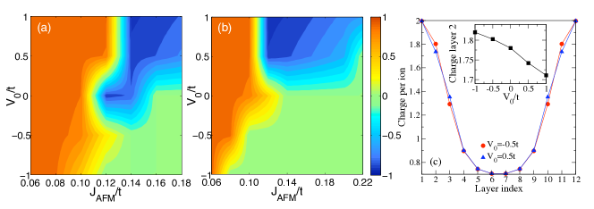
Consider now the effect of the BFO FE polarization. In our study, we assume that the main effect of switching the FE polarization is to modify the induced charge density at the FE surface. As a consequence, the FE nature of BFO makes the heterostructure work as a field-effect device BFO_LSMO_NM . The direction of the FE polarization is modeled by introducing an additional potential at the surface of BFO (layers 2 and 11) which attracts () or repels () the charge [see Fig. 4 (c)]. Fig. 4, our main result, shows the value of the induced magnetization in BFO, , as a function of and , for (a) zero band-offset, and (b) =. For small values of , a FM BFO layer appears at the interface, parallel to the magnetization on LSMO (=). For larger values of and an attractive , the AFM solution (=) is obtained. This is due to the fact that increasing the density of charge towards produces a decrease in kinetic energy, so the gain in superexchange energy dominates. For large values of and repulsive , a FM BFO layer is obtained which is antiparallel to the magnetization on LSMO (=). This is due to the decrease of the charge density (away from ) at the interface which produces an increase of the - plane kinetic energy, while the superexchange term gains energy by making the spins of layers and antiparallel. Equivalent results are found for different values of the band-offset. Therefore, Fig. 4 explains the experimentally demonstrated control of the EB. The LSMO EB is determined by the magnetic order of the last layer of BFO, via a partial pinning to the AF BFO bulk Ohldag , but this order is strongly affected by an electric field (through changes in ). A magnetic field can also influence the EB, by reducing the effective value of and favoring FM order in the last layer of BFO.
Conclusions. A microscopic model that explains the recently unveiled properties of the BFO/LSMO interface is proposed. The charges and spins couple via the DE and superexchange mechanisms, and our calculations show that the induced magnetic moment in BFO arises from charge transfer between the two materials. The spin arrangement generated at the BFO interfacial layer arises from the frustrating effect caused by the two competing (FM and AFM) tendencies in adjacent layers with different electronic densities rong09 . Our main result is that changing the sign of the BFO ferroelectric polarization modifies the extra charge near the interface, which in turn strongly affects the magnitude and direction of the magnetic moment. This gives rise to the experimentally observed magnetoelectric coupling, and clarifies the origin of the recently observed electric field controlled exchange bias in LSMO/BFO heterostructures.
M.J.C. and L.B. acknowledge funding from MICINN (Spain) through Grant No. FIS2009-08744. M.J.C. also acknowledges the Ramón y Cajal program, MICINN (Spain). J.S. acknowledges European research Council Starting investigator Award STEMOX 239739. S.L., A.M., and E.D. are supported by the U.S. Department of Energy, Office of Basic Energy Sciences, Materials Sciences and Engineering Division.
References
- (1) W. Eerenstein, N.D. Mathur, and J.F. Scott, Nature 442, 759 (2006).
- (2) S. M. Wu et al., Nat. Mat. 9, 756 (2010).
- (3) N. A. Spaldin, S-W Cheong, and R. Ramesh, Phys. Today 63, 38 (2010).
- (4) P. Yu et al., Phys. Rev. Lett. 105, 027201 (2010).
- (5) D. Niebieskikwiat et al., Phys. Rev. Lett. 99, 247207 (2007).
- (6) Z. Sefrioui et al., Adv. Mater. 22, 5029 (2010)
- (7) J. Chakhalian et al., Science 318, 1114 (2007).
- (8) J. Garcia-Barriocanal et al., Adv. Mater. 22, 627 (2010).
- (9) J. Salafranca, M.J. Calderón, and L. Brey, Phys. Rev. B 77, 014441 (2008).
- (10) S. Okamoto, Phys. Rev. B 82, 024427 (2010).
- (11) S. Dong et al., Phys. Rev. Lett. 103, 127201 (2009).
- (12) E. Dagotto, T. Hotta, and A. Moreo, Physics Reports 344, 1 (2001).
- (13) C. Israel, M.J. Calderón, and N.D. Mathur, Mat. Today 10, 24(2007).
- (14) C. Şen, G. Alvarez, and E. Dagotto, Phys. Rev. Lett. 105, 097203 (2010).
- (15) L. Brey, Phys. Rev. Lett. 92, 127202 (2004).
- (16) L. Brey, Phys. Rev. B 75, 104423 (2007).
- (17) S. Dong et al., Phys. Rev. B 78, 201102(R) (2008).
- (18) R. Yu et al., Phys. Rev. B 80, 125115 (2009).
- (19) C. Lin, S. Okamoto, and A. J. Millis, Phys. Rev. B 73, 041104 (2006).
- (20) H. Yang, et al., Appl. Phys. Lett. 92, 102113 (2008).
- (21) M. D. Jong, et al., J. Appl. Phys. 94, 7292 (2003).
- (22) C. Broyden, Math. Comp. 19, 577 (1965).
- (23) H. Ohldag, et al., Phys. Rev. Lett. 91, 017203 (2003).