Mode-filtered electron injection into a waveguide interferometer
Abstract
Injection of mode-filtered electrons into a phase-sensitive four-terminal waveguide Aharonov-Bohm (AB) ring is studied. An individually tuneable quantum point contact (QPC) in a waveguide lead of the GaAs/AlGaAs-ring allows to selectively couple to one-dimensional modes in the ring. Thus, we demonstrate single-mode transport in a multi-mode waveguide structure. Coherent mode-filtering by the lowest QPC subband is verified by non-local bend resistance and phase-sensitive AB interference measurements.
Quantum point contacts (QPCs) and electronic waveguides (EWGs) are realizations of a (quasi)-one-dimensional (1D) charge carrier system and show the distinctive property of quantized transverse momentum resulting in conductance quantization.vanW88 ; whar88 Therefore, QPCs are applied in fundamental charge and spin transport experiments in mesoscopic physics as electronic beam splittersnede07 , sensitive single chargegust08 and spinfolk03 detectors and probes for nonequilibrium dynamics of photogenerated electrons.hof10 Furthermore, QPCs operated in the “0.7-conductance-anomaly” have been discussed to function as (all-electrical) spin polarizers07anom in materials of both highrokh06 ; debr09 and lowreil02 ; grah07 ; yoon07 spin-orbit interaction. It has been suggested that the degree of spin polarization can be probed in a quantum ring - quantum dot device.hilt10 However, in order to investigate QPCs as spin polarizers, firstly their application as mode filters in the lowest subband calls for experimental realization.
Here, we employed a phase-sensitive waveguide Aharonov-Bohm (AB) ringbuch09a ; buch10a ; krei10 in order to investigate the mode-filtering properties of QPCs embedded in complex EWG structures. We studied transport in the EWG interferometer in which a QPC is embedded in one of the waveguide leads. The QPC was tuned to the regime of the first and second occupied subbands. By means of bend resistance and electron interference, we show that the selective coupling of (transverse) 1D modes in the EWGs to modes in the adiabatic QPC leads to coherent mode-filtered transport.
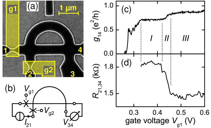
Fig. 1(a) depicts the asymmetric quantum ring comprised of 520 nm wide EWG arms and leads. In the two left waveguide leads two constrictions (QPCs), nm wide and nm long, with metal surface gates g1 and g2 are embedded. From EWG crossing to crossing, the straight and the bent arms of the AB ring are 2.0 and 3.5 m long, respectively.
The device was fabricated by electron beam lithography and wet chemical etching from a GaAs/AlGaAs heterostructure with an electron density of cm-2 and a mobility of cmVs at K (elastic mean free path m). Fabrication details can be found elsewhere.buch09a
Transport properties were measured in a single cool-down in a dilution refrigerator at the base temperature mK with standard lock-in technique. Two-terminal characteristics result from current measurements with a voltage excitation of 40 V rms. Four-terminal measurements were performed with current excitation of 25 nA at 73.3 Hz and voltage metering in a non-local configuration (Fig. 1(b)).buch10a Magnetotransport was investigated in small ( mT) perpendicular magnetic fields with sweep-steps of 30 T.
In the EWG arms of the AB ring 3 to 5 transverse 1D modes with a subband separation of 0.5 to 2 meV are occupied.wg The mode occupation in the QPCs can be tuned by the local gates g1 and g2. While QPC1 was tuned to the first or second subband, QPC2 was kept open at a fixed voltage mV.
Fig. 1(c) shows a two-terminal measurement of the differential conductance from terminal 1 to 4 which is typical for a QPC with a high series resistance: rises in steps as gate voltage increases. The step-like behavior is ascribed to conductance quantization.vanW88 ; whar88 Regions and are the conductance plateaus of the first and second transverse modes in the QPC, respectively. Region in-between marks the transition from the first to the second plateau. The reduced plateau height is explained by the high series resistance which originates partly from the alloyed contacts ( k) and partly from the waveguide resistance.
The discrete subbands of the QPC appear as a signature in the non-local measurement of the transfer (bend) resistance which is a measure of ballistic transport along the EWG arms of the ring and the waveguide crossings.buch09a In Fig. 1(d) is roughly constant in regions and whereas it drops significantly in the transition region .
In a simple model, a QPC’s saddle point potential serves as a 1D mode filter selectively coupling to the modes in the EWGs. Right moving electron waves incident from terminal 1 are coherently transmitted through QPC1 only if the corresponding subband is occupied in the constriction: As an electron wave of transverse mode index approaches the QPC in transport direction its wavefunction gradually conforms to the constriction conserving the quantum number and the spin. Thereby, its longitudinal wavenumber at the Fermi energy decreases, whereas the energetic height of the subband minimum as well as the subband separation increase, i.e. kinetic (longitudinal) energy is commuted to potential (offset and transverse) energy:szaf89 ; vanH92
where is a measure of the transverse harmonic confinement potential and denotes the quantization energy, i.e. the subband separation. Past the saddle point the electron wave gains again and loses potential energy. As a mode of index it continues to propagate in the EWG ring. Electron waves of modes not occupied in the QPC are reflected as they approach the saddle point. This idealized approach requires an adiabatically varying potential in transport direction to prevent intermode scattering at the orifice, ballistic transport for energy conservation, and a QPC constriction length exceeding the decay length of evanescent modes (subbands not occupied in the QPC).glaz88 ; szaf89 ; vanH92 We assume these requirements to be fulfilled in our device, where the constriction width changes gradually on the scale of the wavelength, the QPC length is larger than its width and the entire ring is shorter than the electrons’ mean free path.
The QPC’s selective coupling to EWG modes has a significant influence on the transport through the attached AB ring (Fig. 1(d)). In the non-local measurement configuration, part of the electrons injected through the QPC from terminal 1 travel ballistically along the straight waveguide to terminal 4 (bend resistance).bara90 ; buch09a ; avis89 ; kaku91 The probability to reach terminal 4 depends on the transverse mode and the forward-directed longitudinal momentum . In the lowest mode, electrons have high and their transverse wavefunction maximum is centered in the middle of the waveguide. In the second mode, the two wavefunction maxima are closer to the waveguide boundaries and .

Hence boundary-scattering and scattering in the EWG cross-junctions is increased in the second mode.krei10 ; avis89 ; bara90 The resulting effect is well pronounced at the onset of a new QPC subband: Electrons in the upper subband participate in transport, which leads to an abrupt drop of the total forward transmission along the waveguide crossings. Consequently, drops abruptly in Fig. 1(d) with the onset of the second QPC subband (region ) as observed in the bend resistance of single EWG cross-junctions.avis89 ; bara90 ; kaku91 Since in the EWGs is constant, does not vary with for a fixed number of modes.
The constant in the EWGs has an additional consequence. As is varied we do not expect a phase shift of the AB interference pattern. A phase-sensitive AB ring detects such an AB resistance oscillation phase shift if is varied in one arm of the ring koba02 or if is varied in both arms of an asymmetric ring.buch10a ; krei10
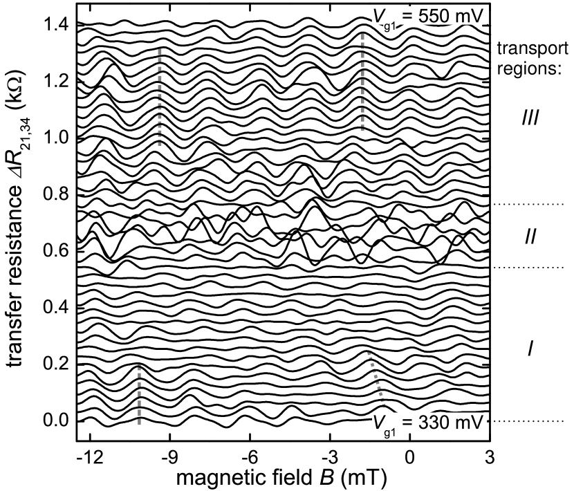
AB measurements were performed to probe coherence in the different transport regions I and III, i.e. the different QPC injection modes, and to verify the independence of electrons’ in the EWG on in the QPC. A non-local measurement allows for phase-sensitivity in the chosen asymmetric EWG ring design.buch10a ; krei10 Fig. 2 shows a typical magnetotransport measurement of for mV (lowest QPC subband, region ) and explains our filtering procedure applied to all AB measurements. First, we subtracted the background (gliding average) of each unfiltered measurement (Fig. 2(a)). The corresponding fast Fourier transform (FFT) is depicted in Fig. 2(c). The peak at 0.5 1/mT agrees with the expected oscillation period. Second, we removed the high frequency noise superimposed on the and possible oscillations by the application of a FFT bandpass-filter with cutoff frequencies 0.1 and 1.2 1/mT.
Further AB measurements of were recorded for succeeding gate voltages from 330 to 550 mV in steps of 5 mV. Fig. 3 shows the filtered data and indicates the three QPC transport regions. For electrons injected via the first () and the second () QPC subband the AB oscillations are mostly regular in period (dominating period) and phase relation. However, in region some deviations are visible: The phase shifts in the lower half of region for mT (dotted line), and few curves show periods. Region shows less deviations from single period oscillations with non-varying phase (dashed lines). The average oscillation amplitude and the visibilitybuch10a in region are higher than in , namely 24 and 1.6 () compared to 15 and 0.8 (). Like the bend resistance, the interference amplitude also depends on the transverse electron wavefunction and associated forward and sideward transmission probabilities and in the EWG cross-junctions.krei10 Hence, for electron waves propagating in the lowest EWG subband, high yields a higher background (bend) resistance (Fig. 1(d)) but a less pronounced interference amplitude compared to electrons of higher subbands whose is higher. Consequently, the increased AB resistance amplitude in region is a further indication for the mode-filtering property of QPC1.
Region in Fig. 3, which corresponds to the onset of the second QPC subband, reveals interference patterns with significantly higher AB amplitudes than in regions and of which some are distinct oscillations. This irregular behavior suggests a correlation to the onset of the second QPC subband but still remains to be understood in detail.
In conclusion, we demonstrated coherent mode-filtered electron injection into a waveguide AB ring. A QPC allows for the selective coupling of transport modes in the QPC to modes in the EWG ring, where transport in the lowest mode is of particular interest. Bend resistance and electron interference were measured: While the non-local transfer (bend) resistance drops with the onset of the second QPC subband the corresponding interference amplitude rises, as is expected from considerations of the transverse wavefunction spread and associated transmission probabilities in the waveguide cross-junctions. An AB phase shift is hardly visible indicating a fixed longitudinal momentum in the EWG ring. Hence, proposed investigations with respect to spin and coherence propertieshilt10 appear feasible in the regime of the QPCs’ “0.7-conductance-anomaly”.
The authors appreciate funding by the DFG within the priority program SPP1285. SFF gratefully acknowledges support by the Alexander-von-Humboldt Foundation.
References
- (1) B. J. van Wees, H. van Houten, C. W. J. Beenakker, J. G. Williamson, L. P. Kouwenhoven, D. van der Marel, C. T. Foxon, Phys. Rev. Lett. 60, 848 (1988).
- (2) D. A. Wharam, T. J. Thornton, R. Newbury, M. Pepper, H. Ahmed, J. E. F. Frost, D. G. Hasko, D. C. Peacockt, D. A. Ritchie, G. A. C. Jones, J. Phys. C: Sol. State Phys. 21, L209 (1988).
- (3) e.g. I. Neder, N. Ofek, Y. Chung, M. Heiblum, D. Mahalu, V. Umansky, Nature 448, 333 (2007).
- (4) e.g. S. Gustavsson, R. Leturcq, M. Studer, T. Ihn, K. Ensslin, D. C. Driscoll, A. C. Gossard, Nano Lett. 8, 2547 (2008).
- (5) J. A. Folk, R. M. Potok, C. M. Marcus, V. Umansky, Science 299, 679 (2003).
- (6) K.-D. Hof, F. J. Kaiser, M. Stallhofer, D. Schuh, W. Wegscheider, P. H nggi, S. Kohler, J. P. Kotthaus, A. W. Holleitner, Nano Lett. 10, 3836 (2010).
- (7) See the special issue on the 0.7-feature: J. Phys.: Condens. Matter 20, 160301 - 164217 (2008).
- (8) L. P. Rokhinson, L. N. Pfeiffer, K. W. West, Phys. Rev. Lett. 96, 156602 (2006).
- (9) P. Debray, S. M. S.Rahman, J. Wan, R. S. Newrock, M. Cahay, A. T. Ngo, S. E. Ulloa, S. T. Herbert, M. Muhammad, M. Johnson, Nature Nanotechn. 4, 759 (2009).
- (10) D. J. Reilly, T. M. Buehler, J. L. O Brien, A. R. Hamilton, A. S. Dzurak, R. G. Clark, B. E. Kane, L. N. Pfeiffer, K. W.West, Phys. Rev. Lett. 89, 246801 (2002).
- (11) A. C. Graham, D. L. Sawkey, M. Pepper, M. Y. Simmons, D. A. Ritchie, Phys. Rev. B 75, 035331 (2007).
- (12) Y. Yoon, L. Mourokh, T. Morimoto, N. Aoki, Y. Ochiai, J. L. Reno, J. P. Bird, Phys. Rev. Lett. 99, 136805 (2007).
- (13) B. Hiltscher, M. Governale, J. König, Phys. Rev. B 82, 165452 (2010).
- (14) S. S. Buchholz, S. F. Fischer, U. Kunze, D. Reuter, A. D. Wieck, Appl. Phys. Lett. 94, 022107 (2009).
- (15) S. S. Buchholz, S. F. Fischer, U. Kunze, M. Bell, D. Reuter, A. D. Wieck, Phys. Rev. B 82, 045432 (2010).
- (16) C. Kreisbeck, T. Kramer, S. S. Buchholz, S. F. Fischer, U. Kunze, D. Reuter, A. D. Wieck, Phys. Rev. B 82, 165329 (2010).
- (17) 1D subband occupation and spacing of EWGs was determined from separate measurements on simple waveguides (widths 350 to 550 nm) with and without embedded QPCs.
- (18) A. Szafer, A. D. Stone, Phys. Rev. Lett. 62, 300 (1989).
- (19) H. van Houten, C. W. J. Beenakker, B. J. van Wees, Semicond. Semimetals 35, 9 (1992).
- (20) L. I. Glazman, G. B. Lesovik, D. E. Khmel’nitskii, R. I. Shekhter, JETP Lett. 48, 238 (1988).
- (21) H. U. Baranger, Phys. Rev. B 42, 11479 (1990).
- (22) Y. Avishai, Y. B. Band, Phys. Rev. Lett. 62, 2527 (1989).
- (23) T. Kakuta, Y. Takagaki, K. Gamo, S. Namba, S. Takaoka, K. Murase, Phys. Rev. B. 43, 14321 (1991).
- (24) K. Kobayashi, H. Aikawa, S. Katsumoto, and Y. Iye, J. Phys. Soc. Jpn. 71, 2094 (2002).