Department of Physics, Purdue University, West Lafayette, Indiana 47907
Colloids Classical transport
The Effect of Pinning on Drag in Coupled One-Dimensional Channels of Particles
Abstract
We consider a simple model for examining the effects of quenched disorder on drag consisting of particles interacting via a Yukawa potential that are placed in two coupled one-dimensional channels. The particles in one channel are driven and experience a drag from the undriven particles in the second channel. In the absence of pinning, for a finite driving force there is no pinned phase; instead, there are two dynamical regimes of completely coupled or locked flow and partially coupled flow. When pinning is added to one or both channels, we find that a remarkably rich variety of dynamical phases and drag effects arise that can be clearly identified by features in the velocity force curves. The presence of quenched disorder in only the undriven channel can induce a pinned phase in both channels. Above the depinning transition, the drag on the driven particles decreases with increasing pinning strength, and for high enough pinning strength, the particles in the undriven channel reach a reentrant pinned phase which produces a complete decoupling of the channels. We map out the dynamic phase diagrams as a function of pinning strength and the density of pinning in each channel. Our results may be relevant for understanding drag coupling in 1D Wigner crystal phases, and the effects we observe could also be explored using colloids in coupled channels produced with optical arrays, vortices in nanostructured superconductors, or other layered systems where drag effects arise.
pacs:
82.70.Ddpacs:
05.60.CdThere are many examples of one- and two-dimensional (1D and 2D) coupled bilayers or coupled channels of interacting particles, including vortices in superconducting bilayers [1, 2], colloidal systems [3, 4, 5, 6], dusty plasmas [7], and Wigner crystals [8, 9, 10]. In many of these systems it is possible to apply an external drive to one of the layers and measure the resulting response of the other layer as well as the drag effect produced by the particles in the undriven layer on those in the driven layer. For instance, this type of measurement has been performed for the transformer geometry in two-layer superconducting vortex systems [1, 2]. If the vortices in each layer are completely coupled, the measured response is the same in both layers. If instead the vortices are only partially coupled between layers, the response is reduced in the undriven layer compared to the driven layer. A similar coupling-decoupling transition is also predicted for coupled wires containing 1D Wigner crystals [8], and certain drag effects in 1D wires have been interpreted as resulting from the formation of 1D Wigner crystal states [9].
Many of these systems can contain some form of quenched disorder which could produce pinning effects [11]; however, very little is known about how pinning alters the drag or transport properties in layered geometries. The quenched disorder could be strong in one channel and weak in another, or it could be of equal strength in both channels, resulting in different types of dynamic phases. Particles driven over random quenched disorder in single layer systems are known to exhibit a variety of dynamical phases associated with distinct transport signatures, as shown in simulations [11, 12, 13, 14] and experiments [15]. These studies suggest that distinct dynamics could also arise in a two-layer drag system when pinning is present. We note that there have been studies of two-layer driven colloidal systems; however, the effect of quenched disorder was not considered [4].
In this work we propose a simple model of two coupled 1D channels of particles with repulsive Yukawa interactions where there a drive channel and a drag channel, and where pinning is added to one or both channels. Despite the apparent simplicity of this system, we find that a remarkably rich variety of distinct dynamical phases are possible which produce pronounced changes in the transport and drag effects. Although our model treats 1D channels, we expect that many of the same effects should be generic to coupled layer systems with quenched disorder. The specific system we consider could be realized experimentally using colloidal particles in channel geometries [16] where a driving force is applied to one channel via optical means or an electric field. The effects we observe could also be studied with coupled 1D Wigner crystals [17, 11, 9, 18] or in superconductors with nanofabricated channel geometries [19] when the current is applied to only one channel and the response is measured in both channels. In our system, we find that without pinning there is a finite drive transition from a locked regime to a partially decoupled regime in which the response of the drag channel decreases with increasing drive. Addition of pinning to the drag channel can induce a pinned phase for both channels. As the drive increases, both channels depin into a locked or partially locked phase, followed at high drives by a reentrant pinning of the drag channel when the dynamic coupling of the two channels becomes weak enough. When the driving force is fixed at a low value, increasing the strength of the pinning in the drag channel increases the effective drag on the particles in the driven channel; for higher fixed driving force, however, increasing the pinning strength reduces the drag on the driven channel and causes the channels to decouple when the drag channel becomes reentrantly pinned. We also observe strong fluctuations in both channels at the locked to partially locked transition for intermediate strengths of quenched disorder. We map out the evolution of the dynamical phases for a wide variety of parameters including pinning in both channels, pinning in only one of the channels, and for varied pinning densities.

Simulation- In fig. 1 we show a schematic of our system which consists of two 1D channels separated by a distance with periodic boundary conditions in the -direction. Each channel contains particles which interact via a repulsive Yukawa potential with other particles in the same channel and with particles in adjacent channels. Particles in the upper or drive channel are subjected to an applied external force . A single particle located at position undergoes motion obtained by integrating the overdamped equation of motion:
| (1) |
Here is the damping constant which is set to . The particle-particle interaction force is where , , , and . Here is the solvent dielectric constant, is the effective charge, and is the screening length. In each channel, the average particle spacing is and we take . We also take to ensure that coupling between the two channels is possible. We note that we have also considered other values of , , and and find the same qualitative features, indicating that our results should be generic for this class of system. The pinning force arises from attractive parabolic potentials with a maximum force of and a radius of , . Here is the Heaviside step function, is the location of pinning site , , and . In this work we consider the limit in which the number of pinning sites is smaller than or similar to the number of particles in the system; however, we find the same qualitative features when we change the pinning density or strength. The external force is applied only to the particles in the driven channel. We increase from zero in small increments of , spending a waiting time of simulation time steps at each increment. We measure the average velocity of the particles in the drive and drag channels, and , where is the number of particles in the drag channel and is the number of particles in the drive channel. This simulation method, employing overdamped dynamics with random pinning, has been used previously to explore the behavior of colloids driven over random and periodic substrates as well as two layer systems. A similar method has been used to study sliding Wigner crystals and vortices in type-II superconductors.
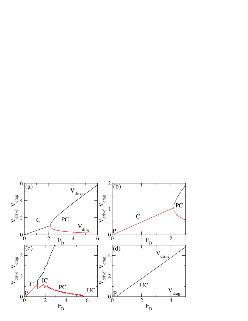
In fig. 2(a) we show the velocity force curves and versus for the case where there is no pinning in either channel. At low , , indicating that the particles are moving together in the coupled region (). At , the average particle velocity in each channel is just under . In the absence of the drag channel, we would have at since under our overdamped dynamics. When the drive channel is locked with the drag channel, the same driving force must be used to transport twice as many particles, reducing the particle velocity by half. At there is a transition to a partially coupled () state where the velocity curves branch apart. continues to increase with increasing with a slope higher than the slope of below , while decreases with increasing . Since there is no pinning, in the region gets smaller and smaller with increasing but never reaches zero. The general shape of the velocity force curves is very similar to the response observed for the superconducting transformer geometry where vortices in a pair of adjacent superconducting layers can couple and decouple depending on the applied current [1, 2]. In the superconducting system, the voltage response is proportional to the particle velocity and the applied current is proportional to . Additionally, the velocity-force curves in fig. 2(a) are in agreement with the predicted coupling-decoupling transition for disorder-free coupled 1D Wigner crystal systems [8].
In fig. 2(b) we plot and versus for a system containing pinning in the drag channel with and . The curves are similar to the pin free case, but a pinned region () now appears for when the quenched disorder in the drag channel causes the particles in both channels to stop moving. The particles in the drag channel are directly pinned by the pinning sites, but the particles in the driven channel are only indirectly pinned by their interactions with the particles in the drag channel, which produce an effective periodic pinning potential for the driven particles. The driven particles can either simply move over this periodic potential, in which case we find a decoupled region () where the driven particles are moving and the drag particles are pinned, or the driven particles can drag the periodic potential along with them, depinning the drag particles and producing a moving coupled region. As increases, there is a transition from the coupled to partially coupled flow at the same as in the pin-free system. Figure 2(c) shows the velocity-force curves for a sample with , where the transition out of region falls at a lower and is followed by a region containing a series of jumps in both and . In this intermittently coupled () region, each downward jump in is preceded by a range of over which increases linearly with increasing . The jumps in are accompanied by similar sharp upward jumps in the value of . As increases, the jumps decrease in size until the system crosses over to the partially coupled () region where decreases linearly and smoothly with increasing . At high , the uncoupled channel () region appears when the particles in the drag channel become pinned again for but the particles in the driven channel continue to flow. The reentrant pinning of the drag channels results when the effective dynamical coupling between the two channels weakens for higher , as indicated by the decrease in with increasing in the region of the pin-free sample shown in fig. 2(a). When the dynamical coupling between the channels drops below a critical value, the drag force experienced by the particles in the drag channel falls below the depinning threshold for the pinning sites in the drag channel, resulting in the repinning transition. We expect this reentrant pinning effect to be a generic feature in drag systems containing quenched disorder, and its signature is a sudden decrease of the drag channel response to zero. In fig. 2(d) for , the drag channel never depins over the range of shown, and there is a single transition from region where both channels are pinned to the decoupled region .

In fig. 3(a) we plot the dynamic phase diagram versus for the system in fig. 2 containing pinning only in the drag channel. The transition between the and regions drops to lower values of with increasing since a lower drive is required to reduce the effective drag force below the depinning threshold of the drag channel at higher . For , only the and regions appear. The extent of region decreases with increasing until region disappears for . The region vanishes at higher values of and reaches its maximum extent near . In fig. 3(b) we plot versus for the same system at fixed . Here decreases with increasing until the system enters the pinned region at and drops to zero. The effective damping of the driven particles, , increases with increasing . In fig. 3(c) we show versus at fixed , where monotonically increases until the system enters the phase, and saturates to a constant value. These results show that pinning in the drag channel can either increase or decrease the effective drag on the driven channel depending on the strength of the pinning and the amplitude of the dc drive.
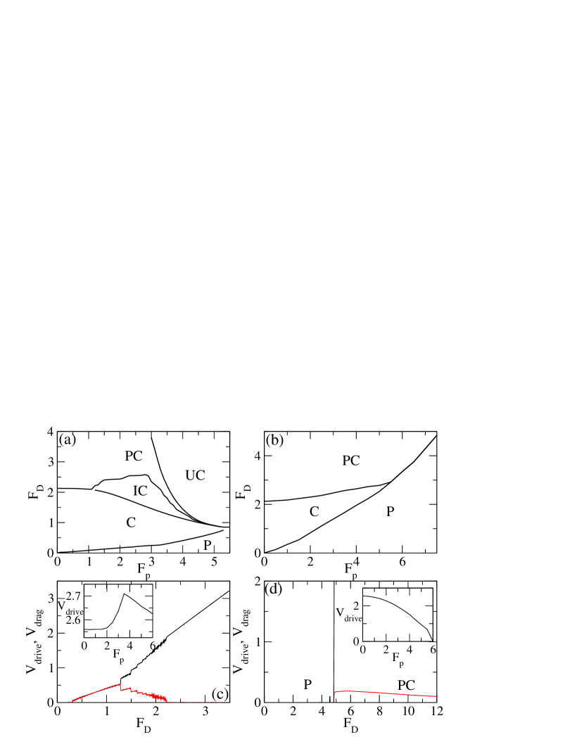
We next consider a system containing pinning in both channels. Figure 4(a) shows the dynamic phase diagram of versus for a sample with a pinning density of in each channel. The overall shape of the phase diagram resembles the phase diagram in fig. 3(a) obtained with pinning in only the drag channel. The pinned phase grows in size with increasing much more rapidly when there is pinning in both channels than when there is pinning in only the drag channel. In fig. 4(c) we plot and versus at for the sample from fig. 4(a) with pinning in both channels. When drops to zero at at the transition to region , there is a jump up in the value of . In fig. 4(b) we show the phase diagram of versus for a sample containing pinning in only the drive channel with . The phase no longer appears since the particles in the drag channel can only reentrantly repin when there is pinning in the drag channel. For , the system crosses directly from region to region without passing through the region. Figure 4(d) illustrates and versus for this system at . There is a transition directly from region to region at , and above this drive gradually decreases with increasing .
In the inset of fig. 4(c) we plot versus at for the system in fig. 4(a) where there is pinning in both channels. For , increases with increasing , just as shown in fig. 3(c) for the sample with pinning in only the drag channel. For , when there is pinning in both channels decreases with increasing for rather than saturating. The increase in with increasing for results when the pinning in the drag channel reduces the coupling between the driven and drag particles. For at , the particles in the drag channel are always pinned. If there is pinning in only the drag channel, remains constant for as shown in fig. 3(c); however, if pinning is also present in the drive channel, it produces an increasing drag on the driven particles, causing to decrease with increasing at for the sample with pinning in both channels. In the inset of fig. 4(d) we illustrate this effect more clearly by plotting vs for a system with pinning in only the drive channel. Here monotonically decreases with increasing until it reaches zero once all the drive particles become pinned.

It is also possible to vary , where is the distance between the channels and is the average particle spacing within the channels. We consider the effect of varying particle density in samples with fixed . Increasing the particle density reduces the effective coupling between the channels since the periodic potential experienced by the particles in one channel produced by the particles in the other channel becomes smoother as the particle density increases. In fig. 5(a) we plot the dynamic phase diagram for versus in a sample with pinning in both channels for fixed and with at . At low , there is a large pinned region since the particles within each channel are far from each other, strongly enhancing the effectiveness of an individual pinning site. For , the system passes directly from region to region . For large , each particle interacts strongly with other particles in the same channel but the coupling to particles in the other channel is greatly reduced, so the system again crosses directly from the pinned to the region. For intermediate values of , the three other regions , , and appear in windows between the and regions. The total width of these intermediate windows reaches a peak at . In fig. 5(b) we show the dynamic phase diagram of versus the pinning density for a system with pinning in only the drag channel at and . The transition from region to region drops to lower with increasing since higher pinning density causes the repinning threshold in the drag channel to decrease. The transition between region and region also shifts to lower with increasing , and there is a narrow window (not labeled on the figure) where region appears between regions and . There is also a small plateau in all of the transitions near , which is a weak commensuration effect. For periodically arranged pinning sites, we expect much stronger commensuration effects to occur; these effects will be considered elsewhere.
In summary, we introduce a simple model to study the effects of pinning on drag in coupled one-dimensional channels of particles interacting via a Yukawa potential where a drive is applied to only one channel. This system exhibits a rich variety of dynamical phases which are associated with distinct features in the velocity-force curves. In the absence of pinning, at low drives both channels are coupled and exhibit identical particle velocities. As the drive is increased, there is a transition to a partially coupled phase where the velocity in the drag channel deceases with increasing drive while the velocity in the driven channel increases with increasing drive. Placing pinning in only the drag channel produces a region in which both channels are pinned as well as a reentrant pinning of the particles in the drag channel at higher drives when the coupling between the channels is dynamically weakened. When strong pinning is placed either in the drag channel or in both channels, we observe only a pinned region and a decoupled region. For intermediate pinning strength, we find a strongly fluctuating region where a series of asymmetric jumps appear in the velocity-force curves. Increasing the strength of the pinning in the drag channel generally reduces the effective drag on the particles in the driven channel at higher drives since the pinned particles in the drag channel are unable to absorb momentum from the particles in the drive channel. We map the dynamic phase diagrams for samples with pinning in both channels, pinning in only the drive channel, and pinning in only the drag channel. The smallest number of phases appears for pinning in only the drive channel, while samples with pinning in both channels exhibit multiple dynamical phase transitions even when the particle density or pinning density is altered, showing that the effects we observe are robust for a wide range of parameters. Our results could be important for understanding drag effects in systems where 1D Wigner crystal states can occur and for understanding the general effects of quenched disorder in other drag and transformer geometries. Additionally, our system could be directly realized experimentally for colloidal or dusty plasma systems in coupled 1D channels. Extensions of this model that could be explored include the effects of a periodic pinning array at and away from commensurability, as well as the effects of disorder on the coupling of particles confined in adjacent two-dimensional planes.
Acknowledgements.
This work was carried out under the auspices of the NNSA of the U.S. DoE at LANL under Contract No. DE-AC52-06NA25396.References
- [1] \Name Giaever I. \REVIEWPhys. Rev. Lett.151965825.
- [2] \Name Clem J.R. \REVIEWPhys. Rev. B91974898; \Name Ekin J.W., Serin B. Clem J.R. \REVIEWPhys. Rev. B91974912.
- [3] \NameMessina R. Löwen H. \REVIEWPhys. Rev. Lett.912006146101.
- [4] \NameDas M., Ananthakrishna G. Ramaswamy S. \REVIEWPhys. Rev. E682003061402; \NameMessina R. Löwen H. \REVIEWPhys. Rev. E732006011405.
- [5] \NameLutz C., Kollmann M. Bechinger C. \REVIEWPhys. Rev. Lett.932004026001;
- [6] \NameHerrera-Velarde S., Zamudio-Ojeda A. Castañeda-Priego R. \REVIEWJ. Chem. Phys.1332010114902; \NameCoste C., Delfau J.-B., Even C. Saint Jean M. \REVIEWPhys. Rev. E812010051201.
- [7] \NameHartmann P., Donkó Z., Kalman G.J., Kyrkos S., Golden K.I. Rosenberg M. \REVIEWPhys. Rev. Lett.1032009245002.
- [8] \NameBaker J.Rojo A.G. \REVIEWJ. Phys.: Condens. Matter1320015313.
- [9] \NameYamamoto M., Stopa M., Tokura Y., Hirayama Y. Tarucha S. \REVIEWScience3132006204.
- [10] \NameGoldoni G. Peeters F.M. \REVIEWPhys. Rev. B5319964591.
- [11] \NamePiacente G. Peeters F.M. \REVIEWPhys. Rev. B722005205208.
- [12] \NameKoshelev A.E. Vinokur V.M. \REVIEWPhys. Rev. Lett.7319943580; \NameFaleski M.C., Marchetti M.C. Middleton A.A. \REVIEWPhys. Rev. B54199612427; \NameOlson C.J., Reichhardt C. Nori F. \REVIEWPhys. Rev. Lett.8119983757; \NameKolton A.B., Domínguez D. Grønbech-Jensen N. \REVIEWPhys. Rev. Lett.8319993061; \NameFily Y., Olive E., Di Scala N. Soret J.C. \REVIEWPhys. Rev. B822010134519.
- [13] \NameReichhardt C. Olson C.J. \REVIEWPhys. Rev. Lett.892002078301; \NameChen J.X., Cao Y. Jiao Z. \REVIEWPhys. Rev. E692004041403; \NameReichhardt C. Olson Reichhardt C.J. \REVIEWPhys. Rev. E792009061403; \NameSengupta A., Sengupta S. Menon G.I. \REVIEWPhys. Rev. B812010144521.
- [14] \NameReichhardt C. Olson Reichhardt C.J. \REVIEWPhys. Rev. Lett.932004176405.
- [15] \NameBhattacharya S. Higgins M.J. \REVIEWPhys. Rev. Lett.7019932617; \NamePardo F., de la Cruz F., Gammel P.L., Bucher E. Bishop D.J. \REVIEWNature3961998348; \NamePertsinidis A. Ling X.S. \REVIEWPhys. Rev. Lett.1002008028303; \NameGuiterrez J., Silhanek A.V., Van de Vondel J., Gillijns W. Moshchalkov V.V. \REVIEWPhys. Rev. B802009140514(R); \NameAvci S., Xiao Z.L., Hua J., Imre A., Divan R., Pearson J., Welp U., Kwok W.K. Crabtree G.W. \REVIEWAppl. Phys. Lett.972010042511.
- [16] \NameKöppl M., Henseler P., Erbe A., Nielaba P. Leiderer P. \REVIEWPhys. Rev. Lett.972006208302; \NameBleil S., Reimann P. Bechinger C. \REVIEWPhys. Rev. E752007031117.
- [17] \NamePiacente G., Schweigert I.V., Betouras J.J. Peeters F.M. \REVIEWPhys. Rev. B692004045324; \NamePiacente G., Hai G.Q. Peeters F.M. \REVIEWPhys. Rev. B812010024108.
- [18] \NameDeshpande V.V. Bockrath M. \REVIEWNature Phys.42008314.
- [19] \NameBesseling R., Kes P.H., Dröse T. Vinokur V.M. \REVIEWNew J. Phys.7200571; \NameYu K., Heitmann T.W., Song C., DeFeo M.P., Plourde B.L.T., Hesselberth M.B.S. Kes P.H. \REVIEWPhys. Rev. B762007220507(R).