Quantum spin Hall effect induced by non-magnetic and magnetic staggered potentials
Abstract
We have a comparative study of the quantum spin Hall (QSH) effects induced by non-magnetic and magnetic staggered potentials respectively and show that they have the same effect in driving the topological phase transition. The result implies that both time-reversal () preserving and breaking systems can host QSH effect. We also investigate the stability of the resulting QSH effect to disorder and find that for invariant system the edge states are always robust while those of breaking system are also robust if there is additional symmetry in the system.
pacs:
73.43.-f, 72.25.Hg, 73.20.-r, 85.75.-dRecently the field of topological insulator (TI) has attracted a great deal of interests, due to their exotic physical properties as well as potential applications, such as spintronics, quantum computing, et al moore1 ; hasan1 ; xlqi1 . Many materials have been predicted and discovered to show TI phases (including quantum wells (QWs) bernevig1 ; konig1 , bismuth antimony alloys hsieh1 ; hsieh2 ; , , and hjzhang1 ; yxia1 ; ylchen1 ; hsieh3 ; Heusler compounds hlin1 ; chadov1 ; Tl-based ternary chalcogenide series hlin2 ; bhyan1 ; et al). The findings of the real materials not only provide a platform to test the predictions of many unusual phenomena exhibited by TI lfu1 ; xlqi2 ; essin1 ; mfranz1 , but also inspire more theoretical studies on TI.
The study of TI begins at the theoretical proposal of QSH effect in graphene by Kane and Mele kane1 ; kane2 . They expected that spin-orbit coupling will convert graphene from an ideal 2D semimetallic state to a QSH insulator. The resulting QSH insulator is topologically distinct from a band insulator, so it is referred as TI. However the calculations have suggested that the spin-orbit coupling in graphene is too small to reveal the QSH effect experimentally ygyao1 . Remarkably, in 2007 the QSH effect was realized in QWs following the theoretical suggestion of Bernevig, Hughes and Zhang bernevig1 ; konig1 . Later though many studies have been carried out in identifying new physical systems that will possess topological nontrivial phases, till now the 2D TI is only found experimentally in QWs. In the low-energy effective theory, the QSH effect can be understood from Dirac Hamiltonian with masses wyshan1 ; sqshen1 . The relative signs of the masses at the Dirac points determine the phases of the system. Alternately, it can also be understood from band inversion, which is the mechanism of the TI phase in QWs. The two ways are equivalent since the occurrence of band inversion corresponds to changing the sign of one Dirac mass and causes a topological phase transition, which can’t happen without closing the gap.
Spin-orbit coupling is a necessary condition for the existence of TI. Its role is to induce a gap in the Dirac dispersion and to ensure that the gap is finite everywhere in the Brillouin zone (BZ). It also has been known that non-magnetic and magnetic staggered potentials can perturb the Dirac dispersion and induce a gap. Such terms can be obtained by the proximity effect to the corresponding orders (charge density wave (CDW) and antiferromagnetism (AF)) hosur1 . When these terms coexist, their interplay will determine the phase of the system. In this paper, we study the interplay of these terms. We start from a trivial insulator with spin-orbit coupling and introduce non-magnetic and magnetic staggered potentials with check-board and stripe patterns into the system. We find that when the strength of the potential is strong enough a band inversion occurs and the system shows QSH effect. Specially the QSH effect induced by magnetic staggered potential breaks symmetry, in contrast to the previously studied QSH effect.
To be concrete, we study a model describing QWs. It resides on a square lattice with four orbit states ( denote the electron’s spin) on each site. In the momentum space, the Hamiltonian writes,
Here and are Pauli matrices representing the orbits and the electron’s spin and is identity matrix. and are four independent parameters. The tight-binding Hamiltonian can be directly obtained by a lattice regulation of the effective low-energy Hamiltonian describing the physics of QWs. We can also view it as a simple toy model conveniently describing both topological and ordinary phases of non-interacting electrons in 2D. The energy spectrum of has two double degenerate branches , where , and . At half-filling, depending on the values of and , the system can be QSH or trivial insulator.
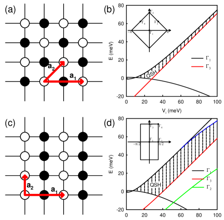
The system defined by Eq. (Quantum spin Hall effect induced by non-magnetic and magnetic staggered potentials) is invariant under and spatial inversion. Since the inversion operator operating on type orbit generates a minus sign, the inversion operator writes . Thus the signs of at the four time-reversal invariant momenta (TRIM) determine the phase of the system, i.e., for QSH (trivial) insulator note1 ; imura1 . In this paper, we restrict our calculations in the parameter range describing QWs, where . Since the TRIM ( in the BZ, see the inset of (b) in Fig. (1)) dominates the physics in the range, the Hamiltonian describes QSH effect for and a trivial insulator for . Experimentally the gap parameter can be continuously tuned from a positive value for thin QWs with thickness to a negative value for thick QWs with ( is a critical thickness and equals nm for QWs) bernevig1 ; konig1 . The gap parameter in Eq. (Quantum spin Hall effect induced by non-magnetic and magnetic staggered potentials) represents an on-site potential, which has different sign for type and type orbits. When changing its sign, one of the occupied bands changes from type () to type (). Since the two kind of orbits have different parities, a band inversion will induce a topological phase transition.
To drive the system into QSH phase, a band inversion is needed. So it is interesting to seek ways other than tuning the gap parameter to generate the band inversion. Below we fix when the system is a trivial insulator and find ways to inverse the bands at TRIM . A natural thought is to enlarge the Hamiltonian, which make it possible to add more terms to it. Firstly we consider putting the system on a check-board square lattice (CSL), which can introduce alternating potential with check-board pattern. In the case, the unit-cell is doubled. The Hamiltonian is enlarged to and becomes,
| (2) | |||
Here is Pauli matrix describing the two sublattices. We have been able to identify two interesting on-site terms: (i) a non-magnetic staggered potential (or CDW potential) ; (ii) a magnetic staggered potential (or AF potential) (The magnetization can also lie in the plane and couples with the in-plane components of the electron’s spin, generating terms like or . We will discuss these terms later). The former term preserves symmetry while the latter breaks. Including the above terms to Eq. (2), though we can’t obtain the analytic forms of the energy spectrums, they are the same for the two different cases. The system remains gapped and the occupied bands evolve with the strength of ().
At TRIM , the energy eigenvalues are: (1) ; (2) ; (3); (4) , where and each is double degenerate. The corresponding eigenvectors and their parities can also be obtained, which are listed in Table I. The band evolvement with the strength is shown in (b) of Fig. (1). At half-filling and for , bands (1) and (2) are occupied. Since we choose , the system is a trivial insulator. As increases, bands (2) and (3) firstly approach each other and at a critical value of the filling for the two bands will interchange. Bands (2) and (3) consist of electrons in the type and type orbits respectively and have opposite parities. For the case with CDW term the band inversion will induce a topological phase transition and drive the system into QSH phase. It is interesting that AF term has the same effect as CDW term. As we further increase the strength of the potential, the system remains in QSH phase until another band inversion occurs at other TRIM, which happens at potential strength bigger than 100 . The gap range of the resulting QSH insulator is also denoted in (b) of Fig. (1). At small potential strength, it is determined by band (2) and (3) and increases with increasing potential strength. Then a band evolving at TRIM ( in the BZ, see the inset of (b) in Fig. (1)) becomes the lower restriction of the gap and restricts its further increase. It is interesting to note that the behavior is similar to what happens in topological Anderson insulator, where the phase diagram has to be obtained by conductivity calculations since the system has no translation symmetry in the presence of disorder jli1 ; hjiang1 ; groth1 ; guo1 .
| Eigenvector(CDW) | Eigenvector(AF) | Parity | |
|---|---|---|---|
| -1 | |||
| -1 | |||
| 1 | |||
| 1 |
We can also put the system on a stripe square lattice (SSL), as shown in (c) of Fig. (1). The Hamiltonian becomes,
| (3) | |||
Similarly, a stripe CDW () or AF term (), which has the same form as its counterpart on CSL, can be added to the above Hamiltonian. The energy spectrums for both cases are still the same. The band evolvements with the potential strength at TRIM are shown in (d) of Fig. (1). The CDW or AF term on SSL can also induce a band inversion and drive the system into QSH phase. However compared to the case in CSL, the band inversion here occurs at smaller potential strength and the resulting QSH insulator has bigger gap.
So adding CDW or AF term to the system can induce a band inversion. Though they have different properties under transformation, they have the same effects on band inversion. The reason is that the combined Hamiltonian at TRIM can be decoupled for each orbit and spin. Each decoupled Hamiltonian has a form and has two sub-bands. The CDW or AF term pushes one sub-band up and the other down, which doesn’t depend on the sign of the potential strength. Since the difference between CDW and AF terms is that AF term acts on different spin with different sign, they have the same effect on changing the band structure.
The CDW term preserves symmetry and such systems can be described by topological invariant kane2 ; lfu2 . Since our system has inversion symmetry, the invariant can be determined from the knowledge of the parities of the occupied band eigenstates at the four TRIM. When the band inversion occurs as we increase the potential strength, the value of the invariant also change its sign and becomes non-trivial, indicating that the system is in QSH phase. For the case with AF term, symmetry is broken and topological invariant is inapplicable. However the spin Hall conductance (SHC) of the resulting QSH phase still shows quantized value zgwang1 . So the underlying topological invariant is a spin Chern number, which describes the quantized spin-Hall conductivity. The concept of spin Chern number has appeared in the recent literature which has its definition for systems with spin conservation dnsheng1 . For invariant systems, it is equivalent to topological invariant lfu2 .
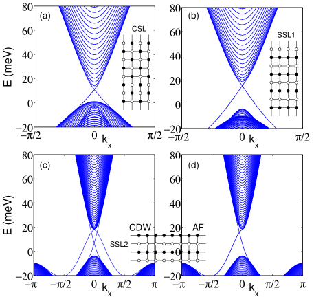
To further support our identification of the topological phase, we have performed numerical diagonalization of Hamiltonian (2) and (3) with CDW or AF term using a strip geometry in the range of parameters where the system is in band-inverted phase. In accord with the above arguments we find a pair of spin-filtered gapless states associated with each edge traversing the gap, which is shown in Fig. (2). The spin-filtered edge states determine the transport of charge and spin in the gap range. For a two-terminal device, the conductance is contributed by two conducting channels on the edges and gets quantized value . For a four-terminal device with proper voltage on each terminal, a spin current can be generated kane1 .
Up to now, we demonstrate the existence of QSH effect induced by non-magnetic and magnetic staggered potential in a trivial insulator with spin-orbit coupling. In the following, we study the stability of the resulting QSH effect to non-magnetic disorder. The Hamiltonian we are considering can be decoupled for spin-up and -down electrons and each describes quantum anomalous Hall (QAH) effect. The resulting QSH effect can be understood as two copies of QAH effect. For the CDW case, the two copies for spin-up and -down electrons are related by and the QSH effect is immune to non-magnetic disorder. However for the AF case, though symmetry is broken, the system preserves the combined symmetry of and a primitive lattice translation, which has been studied in three dimensions and antiferromagnetic topological insulator is predicted mong1 . So the two copies for spin-up and -down electrons in the presence of AF term are related by the combined transformation. If there is non-magnetic disorder in the system, the combined symmetry will be broken and the two copies will behave separately. But we still expect the combined system will be robust to disorder, because each copy is in QAH phase and robust to disorder.
To support the above statement, we employ the recursive Green’s function method to evaluate the conductance of two-terminal devices (see the insets of Fig. (2)) using Landauer-Büttiker formalism. Figure 3 shows the results of such calculations in the space of parameters , where is disorder strength and the disorder is described by a random on-site potential uniformly distributed in the range . We only consider a single disorder realization at each point of the phase diagram. Nevertheless, this turns out to be sufficient for studying the stability of the edge states. The reason is that if the edge states are robust to disorder there should be a region showing quantized conductance in the phase diagram and conductance in the region shows no observable fluctuations, but fluctuates significantly elsewhere. The plots in Fig. (3) displays conductance in a fashion that is designed to amplify the effect of fluctuations. In (a), (b), (d) and (e) of Fig. (3), regions showing no observable fluctuations exist in the phase diagrams, implying that the QSH phase induced by CDW or AF (in channel) terms is robust to disorder. We also carried out calculations on strip SSL2 and the results are similar to those on strip SSL1. These results are consistent with what we expect.
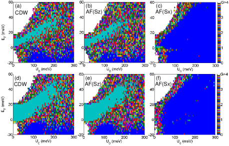
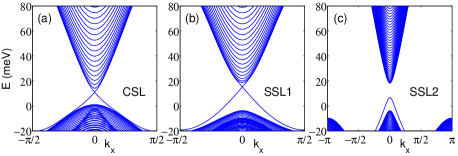
As mentioned, for AF term, the magnetization can also lie in the plane (generating term in or channel) and in the following we will focus on such term. Including such term to Hamiltonian described by Eq. (2) or Eq. (3), the band evolvement at TRIM is exactly the same as that due to CDW or AF potential in channel. However unlike the cases with channel term, the combined Hamitonian can’t be decoupled for spin-up and spin-down electrons (i.e. there is no longer conservation in the system). We perform numerical diagonalization of Hamiltonian (2) and (3) with AF term in channel (it is the same with channel term) and the one-dimensional energy bands with a strip geometry are shown in Fig. (4). For strips CSL and SSL1 (see insets of Fig. (2)), the energy spectrums are similar to those in Fig. (2) and there are edge states traversing the gap in band-inverted phase. But for strip SSL2, the edge states vanish though the system is in band-inverted phase. The difference can be understood from the symmetries existing in the system. AF term in channel couples spin-up and -down electrons and the system only preserves the combined symmetry of and a primitive lattice translation. The existence of edge states is due to the combined symmetry. Since the edges of strip SSL2 are ferromagnetic and break the combined symmetry, the edge states are gapped. However because the combined symmetry on the edges of strips CSL and SSL1 is still preserved, the edge states exist. But these edge states are no longer robust to disorder, which can be shown from conductivity calculations ((c) and (f) of Fig. (3)). Here it is disorder that breaks the combined symmetry and the QSH phase in the system will no longer be protected. While for system with channel term, though ferromagnetic edges or disorder breaks the combined symmetry, the spin conservation follows to assure the existence and robustness of the edge states.
In conclusion, we introduce non-magnetic and magnetic staggered potentials to a trivial insulator with spin-orbit coupling and find that they can induce a topological phase transition and drive the system into topological phase. For non-magnetic staggered potential, the resulting QSH phase is protected by symmetry and supports edge state on any edge, which is robust to disorder. While for magnetic staggered potential, there is a combined symmetry of and a primitive lattice translation in the system. If there is also an additional symmetry i.e., spin conservation, edge states will exist on any edge in band-inverted phase and are robust to disorder. However in the absence of such symmetry, though edge states will exist on specific edges in band-inverted phase, they are no longer robust to disorder. Our these results imply that though generally QSH effect is protected by symmetry but if there are additional symmetries, QSH effect can also be found in breaking systems. .
Acknowledgment.— The authors are indebted to M. Franz, S.-P. Kou, G. Refael, Q.-F. Sun and J.-W. Ye for stimulating discussions. Support for this work came from the funds from Beijing Education Commission under Grant No. KM200910028008, the Ministry of Science and Technology of China under Grant Nos. 2011CBA00102 and 2011CB921700, NSFC under Grant Nos. 10774015 and 11074023, and the Research Grant Council of Hong Kong under Grant Nos. HKU 7051/10P and HKUST3/CRF/09.
References
- (1) To whom correspondence should be addressed.
- (2) J.E. Moore, Nature 464, 194 (2010).
- (3) M.Z. Hasan, C.L. Kane, arXiv: 1002.3895.
- (4) Xiao-Liang Qi and Shou-Cheng Zhang, arXiv: 1008.2026.
- (5) B.A. Bernevig, T.L. Hughes, and S.-C. Zhang, Science 314 1757 (2006).
- (6) M. König, S. Wiedmann, C. Brüne, A. Roth, H. Buhmann, L. W. Molenkamp, X.-L. Qi, and S.-C. Zhang, Science 318, 766 (2007).
- (7) D. Hsieh, D. Qian, L. Wray, Y. Xia, Y. S. Hor, R. J. Cava and M. Z. Hasan, Nature 452, 970 (2008).
- (8) D. Hsieh, Y. Xia, L. Wray, D. Qian, A. Pal, J. H. Dil, J. Osterwalder, F. Meier, G. Bihlmayer, C. L. Kane, Y. S. Hor, R. J. Cava and M. Z. Hasan, Science 323, 919 (2009).
- (9) H. Zhang, C.-X. Liu, X.-L. Qi, X. Dai, Z. Fang, and S.- C. Zhang, Nature Phys. 5, 438 (2009).
- (10) Y. Xia, D. Qian, D. Hsieh, L. Wray, A. Pal, H. Lin, A. Bansil, D. Grauer, Y. S. Hor, R. J. Cava and M. Z. Hasan Nature Phys. 5, 398 (2009).
- (11) Y. L. Chen, J. G. Analytis, J.-H. Chu, Z. K. Liu, S.-K. Mo, X. L. Qi, H. J. Zhang, D. H. Lu, X. Dai, Z. Fang, S. C. Zhang, I. R. Fisher, Z. Hussain, and Z.-X. Shen Science 325, 178-181 (2009).
- (12) D. Hsieh, Y. Xia, D. Qian, L. Wray, F. Meier, J. H. Dil, J. Osterwalder, L. Patthey, A. V. Fedorov, H. Lin, A. Bansil, D. Grauer, Y. S. Hor, R. J. Cava and M. Z. Hasan, Phys. Rev. Lett. 103, 146401 (2009).
- (13) H. Lin, L.A. Wray, Y. Xia, S. Jia, R.J. Cava, A. Bansil and M.Z. Hasan, Nature Mater., 9, 546 (2010).
- (14) Stanislav Chadov, Xiaoliang Qi, Jürgen Küler, Gerhard H. Fecher, Claudia Felser and Shou Cheng Zhang, Nature Mater., 9, 541 (2010).
- (15) H. Lin, R.S. Markiewicz, L.A. Wray, L. Fu, M.Z. Hasan and A. Bansil, arXiv: 1003.2615.
- (16) Binghai Yan, Chao-Xing Liu, Hai-Jun Zhang, Chi-Yung Yam, Xiao-Liang Qi, Thomas Frauenheim and Shou-Cheng Zhang, arXiv: 1003.0074.
- (17) L. Fu and C. L. Kane, Phys. Rev. Lett. 100, 096407 (2008).
- (18) X.-L. Qi, T.L. Hughes, and S.-C. Zhang, Phys. Rev. B78 195424 (2008).
- (19) A.M. Essin, J.E. Moore, and D. Vanderbilt, Phys. Rev. Lett. 102, 146805 (2009).
- (20) B. Seradjeh, J.E. Moore and M. Franz, Phys. Rev. Lett. 103, 066402 (2009).
- (21) C. L. Kane and E. J. Mele, Phys. Rev. Lett. 95, 226801 (2005).
- (22) C. L. Kane and E. J. Mele, Phys. Rev. Lett. 95, 146802 (2005).
- (23) Yugui Yao, Fei Ye, Xiao-Liang Qi, Shou-Cheng Zhang and Zhong Fang, Phys. Rev. B75, 041401 (2007).
- (24) Wen-Yu Shan, Hai-Zhou Lu and Shun-Qing Shen, New J. Phys. 12, 043048 (2010).
- (25) Shun-Qing Shen, Wen-Yu Shan and Hai-Zhou Lu, arXiv: 1009.5502.
- (26) Pavan Hosur, Shinsei Ryu and Ashvin Vishwanath, Phys. Rev. B81, 045120 (2010).
- (27) The conditions can also be simplified as for QSH insulator and for trivial insulator with , and . Here in the range of QSH insulator, is also a critical transition point, where the bands close and the system becomes a semi-metal. Though the syetems at the two sides are still topological non-trivial insulator, the gapless states appear at () for ().
- (28) Ken-Ichiro Imura, Ai Yamakage, Shijun Mao, Akira Hotta, and Yoshio Kuramoto, Phys. Rev. B82 085118 (2010).
- (29) J. Li, R.-L. Chu, J. K. Jain, and S.-Q. Shen, Phys. Rev. Lett. 102 136806 (2009).
- (30) H. Jiang, L. Wang, Q.-F. Sun, and X.-C. Xie, Phys. Rev. B80 165316 (2009).
- (31) C.W. Groth, M. Wimmer, A.R. Akhmerov, J. Tworzydlo, and C.W.J. Beenakker, Phys. Rev. Lett. 103 196805 (2009).
- (32) H.-M. Guo, G. Rosenberg, G. Refael, and M. Franz, Phys. Rev. Lett. 105 216601 (2010).
- (33) L. Fu and C. L. Kane, Phys. Rev. B76, 045302 (2007).
- (34) Zhigang Wang and Ping Zhang, New J. Phys. 12, 043055 (2010).
- (35) D. N. Sheng, Z. Y. Weng, L. Sheng and F. D. M. Haldane, Phys. Rev. Lett. 97, 036808 (2006).
- (36) Roger S. K. Mong, Andrew M. Essin and Joel E. Moore, Phys. Rev. B81, 245209 (2010).