Production of picosecond, kilojoule, petawatt laser pulses via Raman amplification of nanosecond pulses
Abstract
Raman amplification in plasma has been promoted as a means of compressing picosecond optical laser pulses to femtosecond duration to explore the intensity frontier. Here we show for the first time that it can be used, with equal success, to compress laser pulses from nanosecond to picosecond duration. Simulations show up to 60% energy transfer from pump to probe pulses, implying that multi-kilojoule ultra-violet petawatt laser pulses can be produced using this scheme. This has important consequences for the demonstration of fast-ignition inertial confinement fusion.
pacs:
52.38.-r, 42.65.Re, 52.38.Bv, 52.38.HbThe demonstration of fast-ignition (FI) inertial confinement fusion (ICF) involves two phases: the compression of deuterium-tritium fuel to high density and the formation of a hot spot region on the side of the fuel at peak compression via the stopping of energetic (1–3 MeV) electrons generated by an intense picosecond laser pulse. atzeni ; honrubia . Even with the deployment of different magnetic collimation concepts, between 40 kJ - 100 kJ of laser energy needs to be delivered within 16 ps to produce an electron beam with the required properties atzeni ; kemp ; norreys ; wei ; tabak . High-energy petawatt beams of 1-10 picosecond duration are difficult to generate using conventional solid-state laser systems.
Previous studies of Raman amplification have concentrated on reaching the intensity frontier, which requires ultra-short pulses in the femtosecond regime shvets98 ; shvets99 ; malkin05 ; ren07 ; ping09 ; trines10 ; kirkwood11 . Here we present novel particle-in-cell simulations, supported by analytic theory, that confirm that Raman amplification of high-energy nanosecond pulses in plasma can generate efficient petawatt peak power pulses of picosecond duration with high conversion efficiency (up to 60%). The scheme can easily be scaled from to 3 pulses: only the plasma density needs to be adjusted such that the ratio remains fixed (where is the laser frequency, its wave length, is the plasma frequency, and is the plasma electron density, while , and have their usual meaning). This scheme provides a new route to explore the full parameter space for the realisation of the fast ignition inertial confinement fusion concept in the laboratory. This work also opens up a wide range of other high energy density physics research applications, including monochromatic Kα x-ray park , proton beam borghesi and Compton radiography of dense plasmas tommasini , among many others.
Raman amplification in plasma (characteristic plasma frequency ) works as follows shvets98 ; shvets99 . A long pump laser beam (frequency , wave number ) and a counter-propagating short probe pulse (frequency , wave number ) interact via a longitudinal plasma wave (frequency , wave number ) via the process known as stimulated Raman backscattering forslund . This causes a large fraction of the energy of the long pump pulse to be transferred to the short probe pulse. Because the amplified probe is normally up to 1000 times shorter than the pump, its final power can be hundreds of times higher than that of the pump beam.
Raman amplification of ultra-short ( fs) pulses at high intensities was the subject of an extensive recent investigation trines10 . In the case of FI in ICF, however, the compression of long (nanosecond) pump beams to medium (picosecond) duration is needed. This cannot be done by simply extending the scheme of Ref. trines10 (pump intensities of W/cm2) to longer pump pulses because of the increasing influence of pump and probe instabilities, probe saturation and probe shortening at longer interaction lengths. However, it follows from the self-similar theory of Raman amplification developed by Malkin, Shvets and Fisch shvets99 that ns-to-ps compression can be accomplished by reducing the intensities of pump and probe. Although the self-similar theory has been used to predict the self-contraction of the probe shvets99 ; kim03 ; clark03a ; clark03b ; malkin05 , it has not been used before to increase the final probe duration. We introduce the dimensionless pulse amplitude , where and denote the peak intensity and wave length of the laser beam (pump or probe) under consideration and () denotes linear (circular) polarisation, and write () to denote the amplitude of the pump (probe) pulse. Following Malkin et al. shvets99 , we find that the probe duration after amplification is given by
| (1) |
where is a constant of the self-similar interaction, for a 1 ps probe at 351 nm and W cm-2, and increases by when the intensity decreases by an order of magnitude. Thus, the probe duration can be increased by keeping the pump intensity low, even for long pump pulses. If one fixes and as in trines10 , then the pump intensity needed to obtain a certain optimal probe duration is given by:
| (2) |
independent of pump laser wave length. As an example, producing a 2 ps probe from a 2 ns pump requires an intensity of W cm-2.
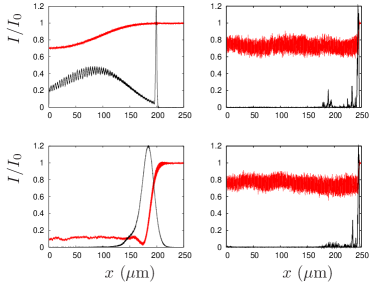
To illustrate this, Figure 1 shows the results of four 1-D particle-in-cell simulations (using the code XOOPIC oopic ) where the pump intensity is either high or low, and the initial probe duration is either long or short. It is found that a low pump intensity leads to a long final probe, while a high pump intensity leads to a short final probe, independent of the initial probe duration.
Limits on the applicability of the self-similar theory are posed by the pump intensity, compression ratio and the frequency ratio . The pump intensity should not exceed the value given by (2) by much, and the compression should not be (much) larger than 1000, both to avoid damage by instabilities. Although increasing will increase the duration of the probe, it will also facilitate wave breaking of the Langmuir wave that couples pump and probe, disrupting the amplification process shvets99 ; using is recommended to prevent this.
Lowering the pump intensity will increase the duration of the amplified probe even further. This has been explored in a series of full particle-in-cell (PIC) numerical simulations using the codes XOOPIC and OSIRIS osiris . In all simulations, the central pump wave length was 351 nm, the plasma density was cm-3 (), and the plasma was initially cold with static ions. In order to infer the effects of the ion motion in the amplification of long pulses, simulation (III) below was repeated with mobile ions (simulation III’). The amplified pulse achieved similar levels of amplification and a good final pulse shape, justifying the use of static ions in the other simulations.
| I | II | III | III’ | IV | V | VI | |
| 0.0044 | 0.003 | 0.0016 | 0.0016 | 0.001 | 0.001 | 0.00056 | |
| 0.0044 | 0.003 | 0.0044 | 0.0044 | 0.003 | 0.001 | 0.00056 | |
| (ps) | 100 | 133 | 100 | 100 | 67 | 133 | 133 |
| (fs) | 65 | 28 | 230 | 330 | 400 | 283 | 2180 |
| Eff.(%) | 20 | 39 | 50 | 40 | 60 | 44 | 7 |
| 14.2 | 7.0 | 8.9 | 10.6 | 6.2 | 7.3 | 11.5 |
The summary of our simulation results is shown in Table 1. Overall, the final probe duration is found to increase with decreasing pump amplitude, and to decrease with increasing pump duration. For simulations (II)-(V), the efficiency is 40-60% and the self-similar parameter ranges from 6 to 9, in reasonable agreement with the theoretical prediction . The poor efficiency in (I) is caused by the combination of high pump intensity and long interaction length, triggering premature pump RBS and probe saturation. The poor efficiency in (VI) is caused by the long start-up time (see below) resulting from the low pump and probe intensities. These simulations also exhibit a relatively high value for , showing that the probe has not yet fully entered the self-similar regime (VI) or has already left it (I).
The amplification of the probe may be affected by a number of instabilities: Raman forward scattering, modulational instability, filamentation, and parasitic RBS of the pump before it meets the probe. Full-scale multi-dimensional PIC simulations are needed to investigate such instabilities properly, see e.g. Ref. trines10 , but this may not be practical given the interaction distances involved (e.g. 150 mm for an 1 ns pump). Nevertheless, the impact of the filamentation, modulational and Raman forward scattering instabilities on the growing probe can be estimated as follows. From Ref. shvets99 , we find that the characteristic growth times for these instabilities are given by and . For a fixed , and compression ratio, e.g. , we have . Then does not depend on , while , i.e. this ratio improves for decreasing . For the filamentation instability in the short-pulse limit, Max et al. max74 or Bingham and Lashmore-Davies bing76 provide a growth rate of , so and , once again improving for decreasing . In short, Raman amplification of long pulses at low intensities suffers less from damaging instabilities than it does for short pulses at high intensities.
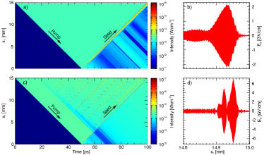
Simulations of the entire plasma column have been conducted, using OSIRIS, to study the stability of a 100 ps pump pulse as it traverses a 15 mm plasma column before it meets the probe. Figure 2 shows the results from simulations (I) and (III) in Table 1, where (III) has a pump intensity of W/cm2, obtained using Eq. (2), while (I) has a much higher intensity of W/cm2, all other parameters identical. For the lower intensity, both pump propagation and probe amplification are stable, and a smooth probe is obtained without precursors. For the higher intensity, the pump suffers from parasitic instabilities, mostly premature RBS, leading to probe precursors, and the probe is shorter while its envelope is less smooth, which is partly caused by the probe taking on the characteristic multi-period -pulse shape. This emphasises the importance of keeping the intensity at or below the value predicted by Eq. (2), when the Raman amplification of a long pump is required.
One issue that is not immediately obvious from the self-similar theory is the existence of a “start-up period” for Raman amplification of low-intensity pulses. The simulations show that when both pump and probe amplitudes are below ( W/cm2 for a m pump wave length), the pump and probe need to interact over several mm before the probe amplification starts in earnest. For a 2 ps initial probe duration, this ranges from less than 2 mm for and 10 mm for to 20 mm for . This follows from the fact that the initial probe amplitude and duration for the ideal self-similar solution are related as ( nm, ). Thus, a 2 ps initial probe duration ideally requires initially. In our simulations, however, is well below that value and the actual probe requires an increasing amount of time to evolve into a self-similar probe for decreasing . Hence the start-up period, whose length also depends on the pump intensity. This effect can be mitigated by increasing the initial probe intensity and/or duration, thus ensuring that the start-up period remains a limited fraction of the pump duration and the overall efficiency remains reasonable even for very low pump intensities.
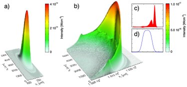
In order to study the stability of the process in multiple dimensions, where transverse instabilities can come into play, we have performed a 2D OSIRIS simulation using the parameters of simulation (III) and a probe spot FWHM of 1.2 mm. This relatively wide probe pulse is efficiently amplified to a peak intensity of Wcm-2, corresponding to a final power of PW (Fig. 3). As predicted for these optimized parameters, transverse instabilities are controlled and the amplified pulse retains a smooth envelope. The bowed shape of the amplified pulse is similar to the shape observed for ultrashort pulses trines10 , and does not influence the amplification process. While the final pulse power significantly exceeds the critical power for self-focusing, GW = 6.8 TW sprangle87 , no significant self-focusing occurs during the interaction, which can be explained as follows. The spot radius of a self-focusing laser pulse in plasma is described by , where is the minimum spot radius in vacuum and is the typical distance for self-focusing, with being the Rayleigh length and the laser power. For a 1.5 PW laser pulse with mm and nm, cm, significantly exceeding the typical amplification distances involved (1.5 – 2 cm). Higher powers require larger spot sizes, since the intensity is fixed by the probe duration and compression ratio; this leads to and . Thus, the influence of self-focusing decreases for increasing probe power.
In the above 2-D simulation, a W/cm2, 100 ps pump has been used to obtain a fs probe with a smooth envelope. In simulation (IV), a W/cm2, 67 ps pump has been used to obtain a 0.4 ps probe. Furthermore, it was shown in ref. trines10 that a 25 ps pump at W/cm2 (800 nm wave length) can be compressed to about 25 fs while probe modulation and RFS remain at an acceptable level. Extrapolating these cases via the self-similar theory, we predict that a 2 ps probe can be obtained using a 2 ns pump at an intensity of W/cm2, in good agreement with the value of W/cm2 predicted by Eq. (2). Assuming the pump beam contains 10 kJ in 2 ns, the pump power will be 5 TW, so a 50 cm2 cross section is needed for the interaction. Such energetic pump beams can be obtained at e.g. the National Ignition Facility moses , the Omega EP laser system at the Laboratory for Laser Energetics in Rochester boehly ; waxer , and the Laser Mégajoule project fleurot .
In summary, we have investigated the Raman amplification and compression of nanosecond laser pulses to picosecond duration, exploiting the self-similar properties of the process. We have shown that, for a constant pump-to-probe compression ratio, the optimal pump and probe durations will increase for decreasing pump intensity. In addition, we have shown that the relative importance of undesirable instabilities remains the same (pump RBS, probe RFS) or even decreases (modulational and filamentation instabilities) with decreasing pump intensity. Energy transfer efficiencies of up to 60% have been found. Thus, Raman amplification in plasma can be used to generate picosecond pulses of moderate intensity but large total energy. This has important consequences for a wide range of applications in high energy density physics, particularly fast-ignition ICF and x-ray and proton radiographic diagnosis of dense plasmas. Most importantly, our approach provides a potential route to the full-scale demonstration of fast ignition inertial confinement fusion using existing facilities.
Work supported by STFC’s Central Laser Facility and Centre for Fundamental Physics, by EPSRC through grant EP/G04239X/1, by the European Research Council (ERC-2010-AdG Grant 267841), and by FCT (Portugal) grants PTDC/FIS/111720/2009 and SFRH/BD/38952/2007. We thank C. Joshi, N. Fisch and R. Kirkwood for stimulating discussions, N. Loureiro for the moving-window antenna in OSIRIS, UC Berkeley for the use of XOOPIC and the OSIRIS consortium for the use of OSIRIS. We acknowledge the assistance of HPC resources (Tier-0) provided by PRACE on Jugene (Germany). Simulations were performed on the Scarf-Lexicon Cluster (STFC RAL), the IST Cluster (IST Lisbon), the Hoffman cluster (UCLA) and the Jugene supercomputer (Germany).
References
- (1) S. Atzeni et al., Phys. Plasmas 15, 056311 (2008).
- (2) J. Honrubia and J. Meyer-ter-Vehn, Plasma Phys. Control. Fusion 51 014008 (2009).
- (3) A.J. Kemp, Y. Sentoku and M. Tabak, Phys. Rev. E 79, 066406 (2009).
- (4) P.A. Norreys et al., Nucl. Fusion 49, 104023 (2009).
- (5) M.S. Wei et al., Phys. Plasmas 15, 083101 (2008).
- (6) M. Tabak et al., Phys. Plasmas, 1, 1626 (1994).
- (7) G. Shvets et al., Phys. Rev. Lett. 81, 4879-4882 (1998).
- (8) V.M. Malkin et al., Phys. Rev. Lett. 82, 4448-4451 (1999).
- (9) V.M. Malkin and N.J. Fisch, Phys. Plasmas 12, 044507 (2005).
- (10) J. Ren et al., Nature Physics 3, 732-736 (2007).
- (11) Y. Ping et al., Phys. Plasmas 16, 123113 (2009).
- (12) R.M.G.M. Trines et al., Nature Physics 7, 87 (2011).
- (13) R.K. Kirkwood et al., Phys. Plasmas 18, 056311 (2011).
- (14) H.-S. Park et al., Phys. Plasmas 13, 056309 (2006).
- (15) M. Borghesi et al., Phys. Plasmas 9, 2214 (2002).
- (16) R. Tommasini et al., Rev. Sci. Instrum. 79, 10E901 (2008).
- (17) D.W. Forslund, J.M. Kindel and E.L. Lindman, Phys. Fluids 18, 1002-1016 (1975).
- (18) J. Kim, H.J. Lee, H. Suk and I.S. Ko, Phys. Lett. A 314, 464 (2003).
- (19) D.S. Clark and N.J. Fisch, Phys. Plasmas 10, 4837 (2003).
- (20) D.S. Clark and N.J. Fisch, Phys. Plasmas 10, 4848 (2003).
- (21) J.P. Verboncoeur, A.B. Langdon and N.T. Gladd, Comp. Phys. Comm. 87, 199-211 (1995).
- (22) R.A. Fonseca, L.O. Silva, R.G. Hemker, et al., Lect. Not. Comp. Sci. 2331, 342-351 (2002).
- (23) C.E. Max, J. Arons and A.B. Langdon, Phys. Rev. Lett. 33, 209-212 (1974).
- (24) R. Bingham and C.N. Lashmore-Davies, Nuclear fusion 16, 67 (1976).
- (25) P. Sprangle, C.-M. Tang, and E. Esarey, IEEE Trans. Plas. Sci. 15, 145-153 (1987).
- (26) E.I. Moses, J. Phys. Conf. Ser. 112, 012003 (2008).
- (27) T.R. Boehly et al., Opt. Commun. 133, 495 (1997).
- (28) L.J. Waxer et al., Opt. Photon. News 16, 30 (2005).
- (29) N. Fleurot, C. Cavailler and J.L. Bourgade, Fusion Engineering and Design 74, 147 (2005).