Misoriented bilayer graphene in a magnetic field: Optical transitions at commensurate angles
Abstract
Misoriented bilayer graphene with commensurate angles shows unique magneto-optical properties. The optical absorption spectra of such a system strongly depend on the angle of rotation. For a general commensurate twist angle the absorption spectra has a simple single-peak structure. However, our studies indicate that there are special angles at which the absorption spectra of the rotated bilayer exhibit well developed multi-peak structures. These angles correspond to even symmetry of the rotated graphene with respect to the sublattice exchange. Magneto-spectroscopy can therefore be a potentially useful scheme to determine the twist angles.
Graphene, mechanically exfoliated from graphite novo display truly remarkable electronic properties review , and holds an immense potential to become a key ingradient for a new generation of electronic devices. The dynamics of electrons in a single sheet of graphene, a hexagonal honeycombed lattice of carbon atoms is that of massless Dirac fermions with linear dispersion, chiral eigenstates, valley degeneracy, and unusual Landau levels in an external magnetic field review . Bilayer graphene, on the other hand, show quadratic dispersion mccann and the charge carriers there are characterized as massive chiral fermions. Interestingly, epitaxial graphene epitaxial , which is thermally grown on the C face of the SiC substrate, as well as graphene grown by chemical vapor deposition (CVD) reina , are multilayer films and yet, quite surprisingly display behavior similar to that of a single layer graphene walt_09 . These systems are known to have a high degree of rotational misalignments hass . Theoretical studies of turbostratic bilayer graphene latil ; turbo ; lopes07 ; mele10 have indicated that in this case the interlayer coupling is suppressed and the systems can be roughly considered as two decoupled layers of graphene. At the same time due to the modulated nature lopes07 of the interlayer transfer integral, these systems show quite rich low-energy physics, which strongly depends on the nature of commensurate stacking faults mele10 .
In a rotated bilayer graphene the rotational stacking fault is determined by an angle of rotation of one layer relative to the other [see Fig. 1(a)]. Each layer consists of two sublattices, A and B, and is characterized by two primitive translational lattice vectors: and , where nm is the lattice constant. The commensurate rotation in a twisted bilayer is defined by the condition lopes07 , , where and are given by the rotation of the primitive vectors and by . The angles corresponding to the commensurate stacking fault are determined from: , where are integers. There are two types of commensurate rotations that are distinguished by their symmetry, even or odd, with respect to the sublattice exchange mele10 . For the even commensurate stacking fault both A and B sublattice sites of the two layers are coincident at some point, while for the odd stacking fault only A sublattice sites of two layers are coincident. The AA-stacking and Bernal stacking correspond to even and odd stacking faults with angles and , respectively.
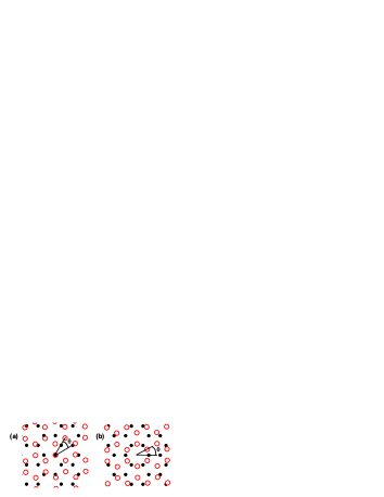
The reciprocal lattice of a graphene layer consist of and sets of points: , , where , and are integers, and are primitive reciprocal lattice vectors, and , . For a rotated layer the reciprocal lattice is rotated by an angle around the origin [see Fig. 1(b)]. Then the even commensurate stacking fault corresponds to the twist angles at which the points of reciprocal lattice of two layers are coincident mele10 , i.e., at some values of , , , and . For odd stacking fault the and points are coincident, i.e., mele10 .
In the case of the commensurate stacking fault the interlayer coupling becomes a periodically modulated function of position, which results in the interlayer coupling determined only by the coincident points of the reciprocal lattice that are found from or . Therefore the interlayer coupling is characterized by the Fourier transform of the interlayer potential, , taken at points : . As a result, the effective low energy Hamiltonian of the twisted layer at commensurate condition takes the form mele10
| (1) |
| (2) |
where , is the electron momentum operator for layer , m/s. The phase angle is determined from , which can have possible values 0 or . For example, for the phase angle is .
For the odd-twisted bilayer the Hamiltonian for all twist angles is identical to the Hamiltonian of a bilayer graphene with Bernal stacking, but with suppressed interlayer coupling. We found new and unique features for the even-twisted bilayer. While at the Hamiltonian of a twisted bilayer is similar to that of a bilayer with AA stacking, at the Hamiltonian of a twisted graphene becomes unique. We show below that this Hamiltonian exhibits interesting features in positions of the Landau levels (LLs) and in magneto-spectroscopy of the rotated bilayer.
Introducing a magnetic field in the Hamiltonians (1)-(2) by replacing the momentum operator with , where is the vector potential, we obtain the LL energies of a twisted bilayer. For odd and even bilayers the interlayer tunneling introduces different coupling structures. For the odd bilayer the LLs of individual layers belonging to different LL indices are coupled, while for the even bilayer the LLs of same indices are coupled.
For the odd bilayer the LL energy spectrum is similar to that of a bilayer graphene with Bernal stacking
where , corresponds to the conduction and valence bands, respectively, and determines the splitting of levels due to interlayer coupling. Here and . For each there are two particle-like and two hole-like LLs.
For the even-twisted bilayer the interlayer tunneling couples the LLs of the two layers with same LL indices, resulting in a splitting of the originally degenerate levels. This splitting depends on . The energy spectrum of a twisted graphene in this case is
| (3) |
where , , . If then , which is a simple splitting of degenerate LLs of the two graphene layers. This energy spectrum is similar to that of AA stacked bilayer. If then . Here the energy splitting of degenerate LLs of two layers is less than the corresponding splitting for .
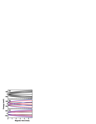
In Fig. 2, the magnetic field dependence of LLs for different types of twisted bilayer are shown for interlayer coupling strength of 50 meV. For the odd graphene bilayer [Fig. 2(a)] the energy spectra is similar to that of a bilayer with Bernal stacking. There is one level with exactly zero energy, which does not show any magnetic field dependence. For the even-twisted bilayer there are two levels without any magnetic field dispersion [Fig. 2(b)]. These levels correspond to the LL index where the energy of the LLs for all values of is . For the LL spectrum depends on the value of . The LL spectrum of even-twisted graphene with [Fig. 2(b)] is similar to that of a bilayer with AA stacking. The LL spectrum of a graphene bilayer with [Fig. 2(c)] shows an unique feature: there is a clear gap-like behavior in the spectrum with no LLs within the interval for all values of the magnetic field.
The LL wavefunctions of the twisted bilayer also depend on the type of commensurate stacking fault. Below we consider in detail only the case of even bilayer, which shows new and interesting features. The wavefunctions for the even-twisted bilayer corresponding to the LLs (3) are
| (4) |
where is the wavefunction of the conventional LL with index , if and if . The phase is defined as
which is nonzero only for nonzero values of . This illustrates the sensitivity of the LL functions of a twisted bilayer to the twist angle.
Armed with the wavefunctions (4) we are now ready to evaluate the strength of the electron-electron interaction within a single LL. This interaction is characterized by the Haldane pseudopotentials haldane and is responsible for formation of the fraction quantum Hall effect (FQHE) states fqhe_book . Since the interlayer coupling in Eq. (4) affects only the phases of the wavefunction components, the pseudopotentials for the wavefunctions (4) are determined only by the LL index and does not depend on the interlayer coupling. The pseudopotentials for the even-twisted bilayer are identical to those of individual graphene layers. Hence the strength of the FQHE in the even-twisted bilayer is the same as in an isolated graphene layer vadim_fqhe . Therefore, as far as the FQHE is concerned, the even-twisted bilayer can be considered as two decoupled graphene layers for any twist angle walt_10 . Since the odd-twisted bilayer is similar to the bilayer graphene with Bernal stacking, the FQHE in an odd bilayer is similar to a bilayer graphene with Bernal stacking bilayer .
The phase in Eq. (4) depends on both the twist angle (through ) and the LL index . Although this phase does not influence the interaction properties within a single LL, importantly, it can modify the optical transitions between different LLs. For light polarized along the axis, the operator of optical transitions is
| (5) |
where is the Pauli matrix. Then the selection rule for the optical transitions between the initial state , and the final state , is the same as for a single graphene layer, i.e., . We consider only the optical transitions to higher excited state, i.e., , as those have higher frequencies and are perhaps easier to observe. The intensity of the corresponding optical transitions is
For the even-twisted bilayer with the phases and are zero. Then the intraband optical transitions (the same sign of ) are allowed only between the states with the same sign of , while the interband optical transitions are allowed between the states with opposite signs of . All transitions have the same intensity. Therefore for a given LL index the optical absorption consists of a single line.
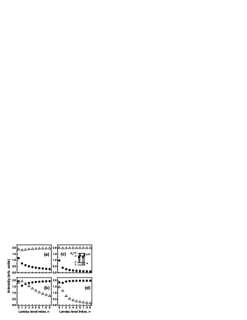
A different situation occurs for the even-twisted bilayer with nonzero values of . In this case both and are nonzero and depend on the LL index . We consider below only the interband optical transitions, i.e., in the initial state (valence band) and in the final state (conduction band). For each initial state there are two transitions to the final states with and . In Fig. 3 the relative intensity of these transitions are shown for different initial LLs and for different magnetic fields. For each LL index the initial and final states are characterized by the parameter . The four possible optical transitions at a given LL index are shown schematically as inset in Fig. 3(c). In Fig. 3(a,c), the transitions from the states with are shown, while in Fig. 3(b,d) the initial state has . The triangles and dots correspond to the final states with and , respectively. The general tendency illustrated in Fig. 3 is the existence of strong transitions to both final states. At a small magnetic field and small LL index, these transitions have comparable intensities [see Fig. 3(a,b) where the magnetic field is 0.5 Tesla]. With increasing LL index the transition to one of the states is suppressed and the system becomes similar to the case of . The regions of magnetic fields and LL indices for which the optical transitions have comparable intensities are determined by the strength of inter-layer transfer integral, . The strongest coupling should be expected for small values of and , e.g., for the twist angle .
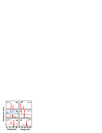
The unique features of optical transitions in the even-twisted bilayer with are clearly visible in the optical absorption spectra. In Fig. 4, we show the absorption spectra from a given LL of the valence band of a twisted bilayer with interlayer coupling of 50 meV. At a given LL index the absorption spectra shown by black solid lines correspond to transition from the ground state with [see the inset in Fig. 3(c)], i.e., only the state with is occupied. The absorption spectra from all the initial states ( and ) with a given LL index are shown by red lines. For the LL index there is only one initial state in the valence band. A 2 meV broadening of the optical lines is introduced in Fig. 4. The absorption spectra clearly show a multi-peak structure which is more pronounced at a small magnetic field [0.5 T in Fig. 4(a-c)] and at small LL index. With increasing magnetic field [see Fig. 4(d-f)] or increasing LL index only one peak in the absorption spectra survives, which is consistent with the results shown in Fig. 3. Such a behavior of the absorption spectra of even-twisted bilayer with is totally different from the odd-twisted graphene or even-twisted with . It is easy to show that for the odd-twisted graphene, which is similar to bilayer graphene with Bernal stacking, only one strong optical transition exists for each LL. Therefore for both odd bilayer and even bilayer with the optical spectra for each LL consist of a single line [Fig. 4(b), ]. Figure 4 clearly shows the fingerprints of phase angle in the magneto-optics of commensurate twisted graphene.
In conclusion, magneto-optical properties of twisted graphene bilayer show strong dependence on the twist angle. At twist angles corresponding to odd bilayer and even bilayer with zero phase angle, , the absorption spectra from a given LL consist of a single line, while the optical spectrum of the even bilayer with nonzero angle has well-developed multi-peak structure which can perhaps be observed experimentally. Such dependence of the optical spectra on the twist angle is visible at low LL index, , and weak magnetic field, Tesla. The strongest multi-peak structure should be observed at large inter-layer coupling, e.g. for the twist angle .
The work was supported by the Canada Research Chairs program.
References
- (1) Electronic address: tapash@physics.umanitoba.ca
- (2) A.K. Geim and K.S. Novoselov, Nat. Mater. 6, 183 (2007).
- (3) D.S.L. Abergel, V. Apalkov, J. Berashevich, K. Ziegler and T. Chakraborty, Adv. Phys. 59, 261 (2010).
- (4) E. McCann, Phys. Rev. B 74, 161403 (2006).
- (5) C. Berger, et al., Int. J. Nanotechnol. 7, 383 (2010).
- (6) A. Reina, et al., Nano Lett. 9, 30 (2009).
- (7) D.L. Miller, et al., Science 324, 924 (2009).
- (8) J. Hass, et al., Phys. Rev. Lett. 100, 125504 (2008).
- (9) S. Latil and L. Henrard, Phys. Rev. Lett. 97, 036803 (2006).
- (10) S. Shallcross, S. Sharma, and O.A. Pankratov, Phys. Rev. Lett. 101, 056803 (2008).
- (11) J.M.B. Lopes dos Santos, N.M.R. Peres, and A.H. Castro Neto, Phys. Rev. Lett. 99, 256802 (2007).
- (12) E.J. Mele, Phys. Rev B 81, 161405 (2010).
- (13) V.M. Apalkov and T. Chakraborty, Phys. Rev. Lett. 97, 126801 (2006).
- (14) Recent observation of the quantum Hall effects in epitaxial graphene seems to corroborate with our theoretical studies of pseudopotentials in a single layer graphene vadim_fqhe . See, Y.J. Song, et al., Nature 467, 185 (2010).
- (15) V. Apalkov and T. Chakraborty, Phys. Rev. Lett. 105, 036801 (2010).
- (16) F.D.M. Haldane, Phys. Rev. Lett. 51, 605 (1983).
- (17) T. Chakraborty and P. Pietiläinen, The Quantum Hall Effects (Springer, Heidelberg, 1995), 2nd edition.