Giant radiation heat transfer through the micron gaps
Abstract
Near-field heat transfer between two closely spaced radiating media can exceed in orders radiation through the interface of a single black body. This effect is caused by exponentially decaying (evanescent) waves which form the photon tunnel between two transparent boundaries. However, in the mid-infrared range it holds when the gap between two media is as small as few tens of nanometers. We propose a new paradigm of the radiation heat transfer which makes possible the strong photon tunneling for micron thick gaps. For it the air gap between two media should be modified, so that evanescent waves are transformed inside it into propagating ones. This modification is achievable using a metamaterial so that the direct thermal conductance through the metamaterial is practically absent and the photovoltaic conversion of the transferred heat is not altered by the metamaterial.
pacs:
78.67.Ch,77.84.Lf,41.20.JbI Introduction
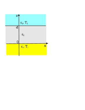
Over the last decade near-field thermo-photovoltaic (NF TPV) systems (e.g. 1 ; 2 ; 3 ) are often considered in the modern literature as a promising tool for the field recuperation from high-temperature sources (industrial waste heat, car engine and exhausting pipe, etc.). Also, NF TPV systems are used as precise temperature profile sensors (e.g. 1 ; 4 ). The operation principle of NF TPV systems is based on the use of the evanescent spatial spectrum, i.e. on the use of the energy of infrared fields stored at nanometer distances from the hot surface. In presence of another body in the near vicinity of the hot surface the well-known photon tunneling phenomenon arises between two surfaces which leads to the dramatic increase of the heat transfer compared to the value restricted by the back-body limit. This transfer can be enhanced if the hot medium, denoted as medium 1 in Fig. 1 (a), and the photovoltaic material, denoted in Fig. 1 (a) as medium 3, both possess negative permittivity 1 ; 5 ; review ; Si . The enhancement holds at a frequency where (when medium 2 is free space) and is related to the excitation of coupled surface-plasmon polaritons (SPP) at the interfaces of media 1 and 3 5 .
In spite of their relatively high efficiency, NF TPV systems suffer strong technological drawbacks which restrict their applicability and industrial adaptation. First, it is difficult to create flat and clean surfaces of Media 1 and 3 separated with a nanogap (the roughness should be much smaller than the gap thickness ). Second, the cryogenic cooling or/and vacuum pumping is required for their operation since the thermal phonons suppress the photovoltaic conversion 1 ; review and the thermal conduction in the air is very high if is smaller than the mean free path of the air molecules ( nm) or comparable with it.
Recently, works on the theory and design of so-called micro-gap TPV (MTPV) systems have appeared (see e.g. in MTPV1 ; MTPV2 ). MTPV systems in which the gap between the photovoltaic and hot surfaces is smaller than the operational wavelengthes but comparable with them occupy an intermediate place between conventional (far-field) TPV and NF TPV systems. This concerns also their efficiency which is much less than that of NF TPV systems though much higher than that of far-field TPV systems. The lack of efficiency is partially reimbursed by strong technological advantages. Attempts to increase the efficiency of MTPV systems are known 1 ; 6 ; MTPV3 related with the use of nanoantennas arrays created on both hot and photovoltaic surfaces or insertion of a photonic crystal layer inside the gap, but the enhancement is not as significant as to justify these complications. In principle, one can strongly increase the radiation heat transfer through the gap partially filling it with a lossless negative-index metamaterial new , however high losses are inherent to such metamaterials and for substantial gaps and known metamaterials this mechanism is not very efficient.
In the present paper we suggest a new paradigm for MTPV systems which should make such structures more competitive than NF TPV systems. We suggest to fill in the gap between Media 1 and 3 with the metamaterial 2, performing the transformation of the evanescent spatial spectrum into propagating one. Metamaterials performing this manipulation with electromagnetic waves are, e.g., the so-called indefinite media Smith – uniaxial materials in which the axial and tangential components of the permittivity tensor has different signs. For the infrared range such metamaterials can be performed as arrays of aligned carbon nanotubes (CNT) IgorPRB ; arxiv . Arrays of aligned metallic CNTs transform incident p-polarized infrared waves (propagating and evanescent) into quasi-TEM waves propagating along CNTs with quite small decay. Unlike the SPP enhancement this effect holds over the whole mid IR range IgorPRB ; arxiv .
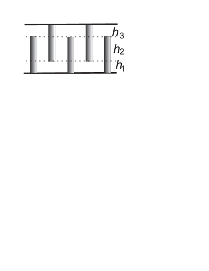
Arrays of single-wall aligned carbon nanotubes with metallic properties are fabricated by many research groups and used as field emitters ShFan , biosensors YLin and antennas Wang ; DresselNat . Such parallel CNTs can be few micrometers long and by two-third of their length free standing (one third is submerged into a dielectric matrix) new2 . It is possible to perform medium 2 so that the direct thermal conduction through CNTs is avoided. A possible scheme is shown in Fig. 1. The area filled with medium 2 is divided by three layers: . Since there is no mechanical contact of any CNT with both media 1 and 3 and, since the array density is assumed to be very small, the thermal conductance through the array of CNTs will be smaller than the thermal conductance through the air gap (for m the last one does not lead to the critical suppression of the photovoltaic conversion).
II Theory
The radiation heat transfer to medium 3 is calculated through the ensemble-averaged Poynting vector created by medium 1 at the input of medium 3 (plane ) minus the backward Poynting vector (calculated at ) Polder . The spectral density of the total heat net transferred between medium 1 with temperature and medium 2 with temperature equals Polder :
| (1) |
In (1) we neglect the heat radiation and absorption in medium 2. This approximation is justified for CNT arrays of small density (ratio diameter/period).
To calculate the Poynting vector (the value is obtained similarly) we first find the incident Poynting vector calculated for the semi-infinite medium 1 neglecting the reflection from the interface between media 1 and 2. Then we apply the transmission matrix method which allows us to express through the incident Poynting vector and known parameters of media 2 and 3. Following to Polder we start from nonhomogeneous Maxwell’s equations with random electric current density sources and apply the fluctuation-dissipation theorem (see e.g. in 1 ; review ) for the ensemble-averaged bulk current density:
| (2) |
In Eq. (2) , and ( or 3) are or component of , is the Kronecker symbol, is the Dirac delta function, and is the mean energy of the Planck oscillator
| (3) |
where is the reduced Planck constant, is the Boltzmann constant, and is the absolute temperature of the medium. According to the ergodic hypothesis, the spectral energy flux of p-polarized waves is expressed as ergodic :
| (4) |
To find the ensemble-averaged product and integrate it over is easy taking into account the homogeneity of the structure in the plane. It allows us to present an elementary bulk current source in a form of a harmonic current sheet:
| (5) |
Without loss of generality we can put here . Solving Maxwell’s equations with the source defined by (5) we obtain horizontal field components created at by the source located at :
| (6) |
where , . The dependence on disappears in the cross product (4). Taking into account that in (2) there is no correlation between different current sheets we can present the integrand in (4) as:
| (7) |
Further, we can rewrite Eq. (2) in the form comprising the current density amplitudes:
| (8) |
Substituting (7) into (4) we easily perform integrating over and ensemble averaging using (8). Integrating over we take into account that
| (9) |
The incident Poynting vector created at the point at the frequency by sources of thermal radiation distributed in medium 1 yields as follows:
| (10) |
Now we have to express the Poynting vector transmitted from medium 1 to medium 3 taking into account the wave reflections from two interfaces. Assuming that Maxwell’s boundary conditions are satisfied at both boundaries we can present it through the wave transmission coefficient and transverse wave impedances of media:
| (11) |
where
| (12) |
The coefficient can be obtained through transmission matrix components of medium 2 in a form Born :
| (13) |
where can be found through the z-component of the wave vector in medium 2:
| (14) |
If the medium 2 is free space and for evanescent waves decays exponentially when (beyond the region of SPP review ; Si ). However, medium 2 formed by CNTs even for very large values of possess real-valued (this is so if we neglect losses in CNTs) and the contribution of spatial frequencies corresponding (in free space) to the evanescent spectrum is important. In our calculations we took into account real losses in CNTs, however these losses practically do not alter the transmission of waves with large .
The applicability of the approach based on the transfer matrix for finite-thickness slabs of aligned CNTs (practically the validity of Maxwell’s boundary conditions at their boundaries) was checked in IgorPRB . Formula (12) and expression (13) for the transfer matrix allow high accuracy when calculating the transmission through a layer filled with a low-density array of aligned CNTs. Since the backward flux calculates similarly to , all we need to complete our model is to relate to for given . For this we used the model of the indefinite medium with permittivity components developed for aligned CNTs in arxiv . Taking into account the interdigital arrangement of CNTs depicted in Fig. 1 the transfer matrix of the whole gap is calculated as the product , where are transfer matrices of layers , and , respectively. Matrix corresponds to a twice more dense array than matrices do.
Now let us assume that media 1 and 3 have the same permittivity given by the Drude formula for heavily doped silicon Si :
| (15) |
where is the high-frequency limit value of the permittivity Markuier , and is the scattering rate. The plasma frequency and scattering rate are expressed as and , respectively, where is the electron charge, is the carrier concentration, is the carrier effective mass, and is the mobility. For -type heavily doped Si (namely this material is used in NF TPV systems enhanced by coupled SPP Si ; review ) the mobility expression is given as Si
| (16) |
Here cm2/V s, cm2/V s, cm2/V s, cm-3, cm-3, , and is the electron concentration.
Fig. 2 presents the comparison of transmittances calculated in presence of the CNT array and in absence (vacuum gap). Calculations were done at the frequency corresponding to the wavelength m. Carriers concentration for -doped silicon was taken cm-3. The width of the gap between media 1 and 3 was equal in this example and thicknesses of sections were as follows: nm, nm. Periods of CNT arrays nm for sections 1 and 3 and nm for the central section 2. Radius of the CNT was taken equal nm and the relaxation time s Achiral .
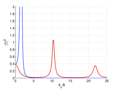
Transmission peaks, exceeding unity, correspond to the excitation of coupled SPP at the interfaces of media 1 and 3 (compare with results of 5 ; 6 ; review ; Si ). The most important peak corresponds to the case of the vacuum gap and is located at spatial frequencies . In presence of CNTs this peak is suppressed. However, instead, multiple peaks of appear in presence of CNTs and (what is most important) , which in absence of CNTs practically vanishes at , in their presence does not. High spatial frequencies correspond to . The limit value corresponds to the condition . For spatial frequencies exceeding this limit value the conversion of evanescent waves into propagating ones disappears (see also in IgorPRB ), and corresponding spatial harmonics practically do not transport energy. Therefore calculating the transferred heat with formula (1) we implement integration over the Brillouin zone of the CNT lattice with the constant nm. Obviously, the integral over in formula (1) would diverge if we assume that still correspond to waves propagating along the CNT axes.
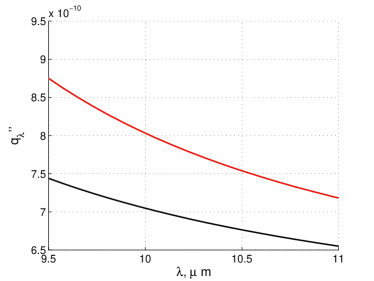
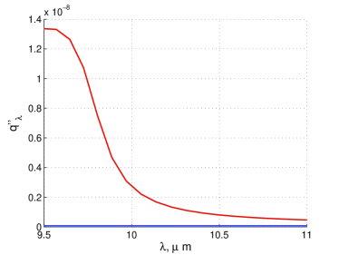
Fig. 3 illustrates the dependence of the spectral density of the transferred heat (the evident analogue of ) for the case, when nm, nm and for nm, nm. The temperatures of the hot and photovoltaic surfaces were in both examples picked up as follows: and . Then the maximal heat transfer corresponds to m and . For the gap nm the insertion of CNTs gives a modest overall enhancement about 20%. This is so because for the gap nm the SPP enhancement (suppressed by CNTs) is still strong. However, for the gap nm, where the SPP enhancement is negligible, the total thermal transfer offered by CNTs exceeds by more than two orders the heat transfer through the vacuum gap. This effect opens a new door for the development of the MTPV systems.
III Conclusion
In this study we have shown the way to revolutionary increase the efficiency of microgap TPV systems inserting between the hot and the photovoltaic bodies a metamaterial which having the negligible thermal conductance converts the evanescent waves into propagating ones in a very broad range of spatial frequencies. We have shown that this conversion can hold over a wide frequency band and lead to a dramatic (2-3 orders) enhancement of the total thermal transfer across the micron gaps.
References
- (1) Zh. Zhang, Nano/microscale heat transfer, McGraw-Hill, Atlanta, Georgia, USA, 2007.
- (2) M. Laroche, R. Carminati, J.-J. Greffet, J. Applied Physics, 100, 063704 (2006).
- (3) K. Park, S. Basu. P. King, Z.M. Zhang, J. Quantitative Spectroscopy and Radiative Transfer, 109, 305 (2008).
- (4) K. Park, A. Marchenkov, Z. M. Zhang, W. P. King, J. Appl. Phys. 101, 094504 (2007).
- (5) J.B. Pendry, J. Phys. Cond. Mat. 11, 6621 (1999).
- (6) C. Fu, Z.M. Zhang, Frontiers of Energy and Power Engineering in China 3, 11 (2007).
- (7) S. Basu, Z.M. Zhang, and C.J. Fu, Int. J. Energy Res. 33, 1203 (2009).
- (8) M.D. Whale, E.G. Cravalho, IEEE Transactions on Energy Conversion 17, 130 (2002).
- (9) R.S. Di-Matteo, P. Greiff, S.L. Finberg, K.A. Young-Waithe, H.K. Choy, M.M. Masaki, C.G. Fonstad, AIP Conf. Proc. 653, 232 (2003).
- (10) I. Celanovic, F. O Sullivan, M. Ilak, J. Kassakian, D. Perreault, Opt. Lett. 29, 863 (2004).
- (11) C. J. Fu, Z. M. Zhang, Microscale Thermophys. Eng. 7, 221 (2003).
- (12) I. S. Nefedov, Phys. Rev. B 82, 155423 (2010).
- (13) I. S. Nefedov, S.A. Tretyakov, C.R. Simovski, An ultra-broadband electromagnetically indefinite medium formed by aligned carbon nanotubes, available at arXiv:1102.5263.
- (14) S. Fan, M.G. Chapline, N.R. Franklin, T.W. Tomber, A.M.. Cassell, H. Dai, Science 283, 512 (1999).
- (15) Y. Lin, F. Lu, Y. Tu, Z. Ren, Nano Letters 4, 191 (2004).
- (16) Y. Wang et al., Appl. Phys. Lett. 85, 2607 (2004).
- (17) M. S. Dresselhaus, Nature 432, 959 (2004).
- (18) Y. Tu, Y. Lin, Z.F. Ren, Nano Letters 3, 107 (2003).
- (19) D. Polder and M. Van Hove, Phys. Rev. B 4, 3303 (1971).
- (20) A.I. Volokitin, B.N.J. Persson, Phys. Rev. B 63, 205404 (2001).
- (21) M. Born and E. Wolf, Principles of Optics (Second edition. Pergamon Press, Oxford-London-New York, 1964).
- (22) D.R. Smith, D. Schurig, Phys. Rev. Lett. 90, 077405 (2003).
- (23) S. Basu, B.J. Lee, Z.M. Zhang, J. of Heat Transfer 132, 023301 (2010).
- (24) F. Markuier, K. Joulain, J.-P. Carminati, J.-J. Greffet, Opt. Commun. 237, 379 (2004).
- (25) G. Ya. Slepyan, M. V. Shuba, S. A. Maksimenko, and A. Lakhtakia, Phys. Rev. B 73, 195416 (2006).
- (26) P. J. Burke, IEEE Trans. on Nanotechnology 3, 129 (2002).
- (27) I. Iijima, Nature 354, 56 (1991).
- (28) G.Y. Slepyan, S. A. Maksimenko, A. Lakhtakia, O. Yevtushenko and A. V. Gusakov, Phys. Rev. B 60, 17136 (1999).