Permanent tuning of quantum dot transitions to degenerate microcavity resonances
Abstract
We demonstrate a technique for achieving spectral resonance between a polarization-degenerate micropillar cavity mode and an embedded quantum dot transition. Our approach is based on a combination of isotropic and anisotropic tensile strain effected by laser-induced surface defects, thereby providing permanent tuning. Such a technique is a prerequisite for the implementation of scalable quantum information schemes based on solid-state cavity quantum electrodynamics.
Single self-assembled quantum dots (QDs) embedded in microcavities are interesting systems for quantum information applications. Cavity-induced Purcell enhancement of the emitter spontaneous emission rate has been exploited to demonstrate efficient and reliable single photon sources Lounis and Orrit (2005); Strauf et al. (2007); Reitzenstein and Forchel (2010). Moreover, quantum information schemes employing cavity quantum electrodynamics with quantum dots coupled to semiconductor microcavities have been proposed and implemented Imamoglu et al. (1999); Reithmaier et al. (2004); Rakher et al. (2009); Hu et al. (2009); Bonato et al. (2010). Such system would provide a scalable platform for hybrid quantum information protocols, in which photonic qubits are used for long-distance transmission and matter qubits for local storage and processing Cirac et al. (1997); van Enk et al. (1997).
Several quantum information applications require a polarization-degenerate cavity mode that is spectrally resonant with a specific quantum dot optical transition Hu et al. (2009); Bonato et al. (2010). Polarization-degeneracy is needed in order to transfer an arbitrary polarization state of a photon to the spin of a single electron confined in the dot, or viceversa. In the case of micropillar cavities, due to residual strain in the structure or small shape asymmetries, the fundamental cavity mode often consists of two linearly-polarized submodes, energy split by an amount . An important issue to note is the fact that the optical properties of a self-assembled quantum dot strongly depend on its specific size and local strain, neither of which is deterministically controllable in the growth process. Therefore post-fabrication tuning techniques are crucial to achieving exact spectral resonance.
The most flexible tuning technique is Stark-shifting: embedding the dots in a diode structure and applying a voltage leads to a shift of the optical transition frequency by the quantum confined Stark effect Fry et al. (2000). Such shifts can be finely tuned to a limited range of a few hundred eV, making the technique most effective in combination with some other coarse tuning procedures, such as temperature or strain. Temperature tuning, of either the whole sample Kiraz et al. (2001) or a local spot Faraon et al. (2007) is an effective approach, with energy shifts on the order of meV reported in the literature. The temperature can, however, only be adjusted in the range of about K: at higher temperatures the dot luminescence quenches. Moreover, if one is interested in the spin of a single electron in the QD, it is crucial to keep the temperature below K, in order to avoid reducing the spin relaxation time Paillard et al. (2001).
Strain-tuning, via piezoelectric actuators or mechanical tips, has also been extensively investigated Obermüller
et al. (1999); Zander et al. (2009); Bryant et al. (2010). Recently, it was shown that strain control by means of laser-induced surface defects can be used to fine-tune the optical properties of semiconductor microcavities van Doorn et al. (1996a); Bonato et al. (2009). By focusing a strong laser beam on a small spot, far away from the cavity center to preserve the optical quality of the device, the local birefringence can be modified. Here we show that, by a controlled combination of anisotropic and isotropic strain, one can simultaneously get a polarization-degenerate cavity and tune a dot optical transition into resonance with the cavity mode. Since the defects are permanent, no external tuning equipment is needed during an experiment, and this makes our technique ideal for scalability purposes.
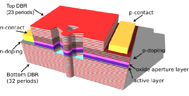
We investigated a sample with quantum dots embedded in micropillar cavities, grown by molecular-beam epitaxy on a GaAs [100] substrate. The microcavity consists of two distributed Bragg reflector (DBR) mirrors, made by alternating layers of GaAs and Al0.9Ga0.1As. Between the mirrors, the active -GaAs layer contains embedded InGaAs/GaAs self-assembled quantum dots and sits underneath an AlAs oxidation layer. Trenches are etched down to the bottom DBR and the sample is placed in asteam oven to define an AlOx oxidation front in the AlAs layer, providing transverse optical-mode confinement which results in high quality factors Stoltz et al. (2005). Using micropillars defined by trench shapes, intra-cavity electrical gating of multiple devices is possible by the fabrication of a PIN-diode structure (see Fig. 1 for a sample diagram).
Defects are created on the sample surface by a laser beam (about 100 mW/m2, nm) tightly focused on the structure for about 30 seconds by a high-NA aspheric lens (focal length mm, ). The material is locally melted and evaporated, leaving a hole which is approximately wide and at least deep. The whole process is performed in a helium-flow cryostat, at a temperature of .
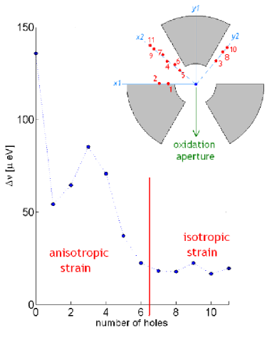
The first step consists of reducing the fundamental cavity mode to polarization-degeneracy, following the procedure described in Bonato et al. (2009). The built-in strain can be compensated by applying anisotropic strain, through holes burnt at proper positions. The direction of the original built-in strain is however unknown, so one must use a trial-and-error procedure, illustrated in Fig. 2. We first start burning a hole at a random orientation, for example along the direction labeled in the figure as . If the splitting gets larger, we move to the orthogonal direction. If the splitting decreases, we keep burning holes until the splitting stops decreasing. In the example shown in Fig. 2, the first hole reduces from eV to eV, but a second one slightly increases it. This is an indication that all the strain along that particular direction was compensated. We repeat the same procedure on a reference system rotated by degrees with respect to . In the example, we start burning the third hole along , which increases the splitting to eV. Therefore we switch to the orthogonal direction . Burning holes along this direction reduces to around eV. The procedure can be further iterated along directions in between and and generally leads to splittings smaller than the mode linewidth (in our system about eV), which is the requirement for quantum information experiments. No appreciable change in the cavity quality factor was observed.
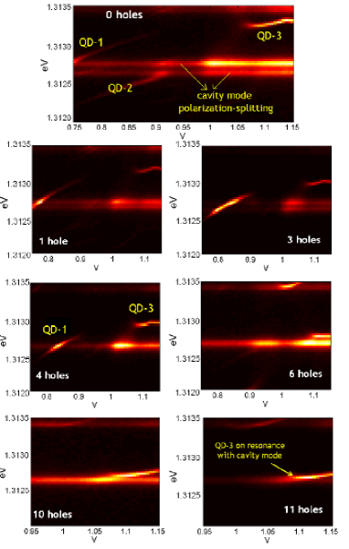
Strain affects the optical transitions of the quantum dots as well. In Fig. 3, we show plots of voltage-resolved photoluminescence from the same microcavity analyzed in Fig. 2. We pump the sample non-resonantly with about 1 W/m2 laser beam at nm, above the GaAs bandgap, and we spectrally resolve the photoluminescence with a spectrometer (resolution eV/pixel). Scanning the voltage of the microstructure PIN-diode, different charged states of the dot can be selected Warburton et al. (2000) and the frequency of the optical transitions can be tuned by the Stark effect Fry et al. (2000). The flat lines in the plots correspond to the fixed frequency emission of the fundamental cavity mode, split into two orthogonally-polarized submodes. The Stark-shifting lines correspond to QD optical transitions.
The effect of laser-induced defects is always a red-shift of the optical transition, independent of the actual position of the hole. The shift of the dot transition is generally much larger than the corresponding shift of the cavity mode, and from a sample of more than one hundred holes burnt, the ratio of the shifts was found to be on average . These findings can be explained with a simple model Bonato et al. . The fact that the optical transition always red-shifts suggests that by burning holes we effectively apply tensile strain to the structure. This could be explained by assuming that, by removing material, we release some compressive strain that pre-exists due to lattice-mismatch in the dot. Such tensile strain affects the band-structure both of the InAs dot material and of the bulk surrounding GaAs, reducing the InAs energy gap and the width of the confining potential well. The change in the band-structure profiles can be shown to be independent of the direction of the strain in the plane of the dot Bonato et al. .
The difference in the way the cavity mode and the dot transition are affected by hole-burning can be exploited to tune a quantum dot transition into resonance with a polarization-degenerate cavity. In Fig. 3 one can see that, while burning the first six holes, needed to reduce the splitting , the optical transitions of the dots red-shift, so that the transitions labeled as QD-1 and QD-2, originally resonant with the non-degenerate fundamental cavity mode, tune out of resonance. After burning six holes we have a polarization-degenerate cavity mode, with a quantum dot transition (labeled QD-3) about eV detuned on the blue-side. Now the challenge is to shift this transition into resonance, without perturbing the cavity mode degeneracy. This can be done by applying isotropic strain: we can burn sets of two holes at orthogonal directions, for example one along and the other along , at the same distance from the center. This leaves the splitting unaltered while red-shifting the dot transition. The results are shown in the bottom two pictures in Fig. 3, corresponding to the tenth and eleventh hole burnt. The dot is finally on resonance and the fundamental cavity mode splitting is eV (right side of Fig. 2, for holes 7-11).
In conclusion, we demonstrated a tuning technique for micropillar cavities with embedded quantum dots, which allows us to obtain polarization-degenerate micropillars with a QD transition on resonance. Our technique is a crucial prerequisite for the implementation of scalable quantum information systems involving photon polarization and the spin of a single carrier trapped in the dot.
This work was supported by the NSF grant 0901886, the Marie-Curie award No. EXT-CT-2006-042580 and FOMNWO grant No. 09PR2721-2. We thank Andor for the CCD camera.
References
- Lounis and Orrit (2005) B. Lounis and M. Orrit, Rep. Progr. Phys. 68, 1129 (2005).
- Strauf et al. (2007) S. Strauf, N. G. Stoltz, M. T. Rakher, L. A. Coldren, P. M. Petroff, and D. Bouwmeester, Nat. Photon. 1, 704 (2007).
- Reitzenstein and Forchel (2010) S. Reitzenstein and A. Forchel, Journal of Physics D: Applied Physics 43, 033001 (2010).
- Imamoglu et al. (1999) A. Imamoglu et al., Phys. Rev. Lett. 83, 4202 (1999).
- Reithmaier et al. (2004) J. P. Reithmaier, G. Sek, A. Loffler, C. Hofmann, S. Kuhn, S. Reitzenstein, L. V. Keldysh, V. D. Kulakovskii, T. L. Reinecke, and A. Forchel, Nature 432, 197 (2004).
- Rakher et al. (2009) M. T. Rakher, N. G. Stoltz, L. A. Coldren, P. M. Petroff, and D. Bouwmeester, Phys. Rev. Lett. 102, 097403 (2009).
- Hu et al. (2009) C. Y. Hu, W. J. Munro, J. L. O’Brien, and J. G. Rarity, Phys. Rev. B 80, 205326 (2009).
- Bonato et al. (2010) C. Bonato, F. Haupt, S. S. R. Oemrawsingh, J. Gudat, D. Ding, M. P. van Exter, and D. Bouwmeester, Phys. Rev. Lett. 104, 160503 (2010).
- Cirac et al. (1997) J. I. Cirac, P. Zoller, H. J. Kimble, and H. Mabuchi, Phys. Rev. Lett. 78, 3221 (1997).
- van Enk et al. (1997) S. J. van Enk, J. I. Cirac, and P. Zoller, Phys. Rev. Lett. 78, 4293 (1997).
- Fry et al. (2000) P. W. Fry, I. E. Itskevich, D. J. Mowbray, M. S. Skolnick, J. J. Finley, J. A. Barker, E. P. O’Reilly, L. R. Wilson, I. A. Larkin, P. A. Maksym, et al., Phys. Rev. Lett. 84, 733 (2000).
- Kiraz et al. (2001) A. Kiraz, P. Michler, C. Becher, B. Gayral, A. Imamoglu, L. Zhang, E. Hu, W. V. Schoenfeld, and P. M. Petroff, Applied Physics Letters 78, 3932 (2001).
- Faraon et al. (2007) A. Faraon, D. Englund, I. Fushman, J. Vučković, N. Stoltz, and P. Petroff, Applied Physics Letters 90, 213110 (pages 3) (2007).
- Paillard et al. (2001) M. Paillard, X. Marie, P. Renucci, T. Amand, A. Jbeli, and J. M. Gérard, Phys. Rev. Lett. 86, 1634 (2001).
- Obermüller et al. (1999) C. Obermüller, A. Deisenrieder, G. Abstreiter, K. Karrai, S. Grosse, S. Manus, J. Feldmann, H. Lipsanen, M. Sopanen, and J. Ahopelto, Applied Physics Letters 75, 358 (1999).
- Zander et al. (2009) T. Zander, A. Herklotz, S. Kiravittaya, M. Benyoucef, F. Ding, P. Atkinson, S. Kumar, J. D. Plumhof, K. Dörr, A. Rastelli, et al., Opt. Express 17, 22452 (2009).
- Bryant et al. (2010) G. W. Bryant, M. Zieliński, N. Malkova, J. Sims, W. Jaskólski, and J. Aizpurua, Phys. Rev. Lett. 105, 067404 (2010).
- van Doorn et al. (1996a) A. K. J. van Doorn, M. P. van Exter, and J. P. Woerdman, Appl. Phys. Lett. 69, 1041 (1996a).
- Bonato et al. (2009) C. Bonato, D. Ding, J. Gudat, S. Thon, H. Kim, P. M. Petroff, M. P. van Exter, and D. Bouwmeester, Applied Physics Letters 95, 251104 (pages 3) (2009).
- Stoltz et al. (2005) N. G. Stoltz, M. Rakher, S. Strauf, A. Badolato, D. D. Lofgreen, P. M. Petroff, L. A. Coldren, and D. Bouwmeester, Appl. Phys. Lett. 87, 031105 (2005).
- Warburton et al. (2000) R. J. Warburton, C. Schaeflein, D. Haft, F. Bickel, A. Lorke, K. Karrai, J. M. Garcia, M. Schoenfeld, and P. M. Petroff, Nature 405, 926 (2000).
- (22) C. Bonato, E. van Nieuwenburg, J. Gudat, S. Thon, H. Kim, M. van Exter, and D. Bouwmeester, in preparation.