Constraints on non-Newtonian gravity from measuring the Casimir force in a configuration with nanoscale rectangular corrugations
Abstract
We report constraints on the parameters of Yukawa-type corrections to Newtonian gravity from measurements of the gradient of the Casimir force in the configuration of an Au-coated sphere above a Si plate covered with corrugations of trapezoidal shape. For this purpose, the exact expression for the gradient of Yukawa force in the experimental configuration is derived and compared with that obtained using the proximity force approximation. The reported constraints are of almost the same strength as those found previously from several different experiments on the Casimir force and extend over a wide interaction range from 30 to 1260 nm. It is discussed how to make them stronger by replacing the material of the plate.
pacs:
14.80.-j, 04.50.-h, 04.80.Cc, 12.20.FvI Introduction
Many extensions of the standard model predict corrections of Yukawa-type to Newton’s gravitational law 1 . These corrections can be caused by the exchange of light elementary particles between pairs of atoms belonging to two macrobodies 2 . Multi-dimensional compactification schemes, where extra dimensions are compactified at relatively low energy of the order of 1 TeV 3 ; 4 ; 5 , also generate Yukawa-type corrections to Newton’s law 6 ; 7 . Constraints on the parameters of Yukawa-type potential, the interaction strength and the interaction range , were traditionally obtained from the Eötvos- and Cavendish-type experiments (see Refs. 1 ; 8 ; 9 for a review). For above a few micrometers the gravitational experiments resulted in strongest constraints on which were used for constraining the masses of predicted light elementary particles and other parameters of the theory of fundamental interactions.
For below a few micrometers, Newtonian gravity becomes much smaller than the Casimir force induced by electromagnetic fluctuations. Because of this, the strongest constraints on non-Newtonian gravity of Yukawa-type in this interaction range follow from experiments on measuring the Casimir force (see Ref. 10 for a review of recent measurements). As a result, previously known constraints on in the submicrometer range were strengthened up to 10000 times (review of all results obtained from measurements of the Casimir force before 2009 can be found in Ref. 11 ). Recently it was also shown that the measure of agreement between precise measurements of the lateral Casimir force in the configuration of sinusoidally corrugated surfaces and exact theory based on the scattering approach 12 ; 13 leads to further strengthening of constraints on in the interaction range nm 13a (note that for below 1 nm the strongest constraints on the Yukawa interactions are obtained 14 from precision atomic physics). There was also recent proposal 15 to measure the gradient of the Casimir force between a plate and a microfabricated cylinder attached to a micromachined oscillator. It was shown 16 that this experiment is expected to obtain up to 70 times stronger constraints on over a wide interaction range from 12.5 to 630 nm.
In the present paper we obtain constraints on the parameters of Yukawa-type corrections to Newtonian gravity resulting from recent measurements 17 of the gradient of the Casimir force between a smooth Au-coated sphere and a Si plate covered with nanoscale rectangular corrugations. This is the first measurement of the Casimir force in the configuration with rectangular corrugations where the experimental data were compared with the exact theory and the measure of agreement was quantified over some range of separations between the test bodies. We calculate the gradient of the Yukawa force acting between an Au-coated sphere and a plate with rectangular corrugations and derive respective constraints determined by the magnitude of this measure. Although the derived constraints are a bit weaker than those of Refs. 18 ; 19 ; 20 , they serve as a confirmation of previous results obtained using quite different experimental configuration and theoretical approach. We also discuss the modifications in the experimental setup used allowing to significantly strengthen constraints on the Yukawa interaction obtainable in the configuration with rectangular corrugated boundary surface.
In Sec. II we briefly describe the parameters of the experimental setup 17 needed for obtaining constraints and derive the measure of agreement between experiment and theory. In Sec. III the derivation of the gradient of Yukawa force in the experimental configuration is presented. This is used in Sec. IV to obtain constraints which are compared with the results following from other experiments. Prospective constraints obtainable in the configuration with a rectangular corrugated plate are considered. Our conclusions and discussion are contained in Sec. V.
II Measuring the gradient of the Casimir force between an Au sphere and a Si plate with rectangular corrugations
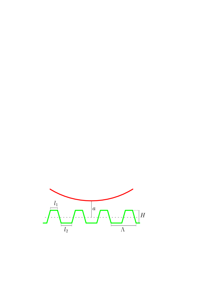
The experimental setup of Ref. 17 includes a micromechanical torsional oscillator with two attached Au-coated spheres of m radii. The thickness of the Au layer on the spheres was nm. This oscillator was used in the dynamic regime to measure the shift of its resonant frequency which is proportional to the gradient of the Casimir force acting between the upper sphere and the Si plate covered with rectangular corrugations. In so doing the distance between both surfaces was measured with high precision. The corrugations were not precisely rectangular, but rather had a trapezoidal form shown in Fig. 1 with the following values of parameters 17 : nm, nm, nm, and nm. The separation is defined between the mean level of corrugations and the bottom point of the sphere closest to the Si surface (in Ref. 17 separations are defined as nm and the corrugated surface is actually situated above the sphere). This experiment is the second in a series of measurements using a rectangular corrugated plate, but the first 22 was not quantitatively compared with theory.
In Fig. 3(d) of Ref. 17 the measurement results with the respective absolute errors as a function of separation were presented for the quantity
| (1) |
Here is the measured gradient of the Casimir force between the sphere and the corrugated plate, and is the same gradient calculated using the proximity force approximation (PFA) 22a ; 23 . According to the general formulation of the PFA 22a , the Casimir force between a sphere and a periodically corrugated plate can be approximately represented by
| (2) |
where is the Casimir force acting between the sphere and a flat element of the corrugated plate spaced at a separation from the sphere. Using Fig. 1, Eq. (2) can be identically rearranged in the form
| (3) |
where (), , and are the distances between the top and the bottom surfaces of corrugations and the mean level shown by the dashed line in Fig. 1:
| (4) |
Equation (3) is equivalent to Eq. (1) of Ref. 17 . For our purposes, however, it can be further simplified.
In application to a sphere above a flat plate at a separation much smaller than the sphere radius, the simplified formulation of the PFA 23 results in
| (5) |
where is the Casimir energy per unit area of two plane parallel material plates expressed by means of the Lifshitz formula 24 . Calculating the derivative of Eq. (3) with respect to the separation, and taking into account Eq. (5) leads to
| (6) |
where is the Casimir pressure between the two parallel material plates expressed by the respective Lifshitz formula 24 . The integral on the right-hand side of Eq. (6) can be calculated taking into account that
| (7) |
The result for the gradient of the Casimir force is
| (8) |
where .
Measurements of the gradient of the Casimir force were performed over the separation region from 200 to 550 nm. As is shown in Sec. IV below, the strongest constraints on the parameters of Yukawa-type interaction follow from the measurement data at separations 279, 384, and 413 nm. From Fig. 3(d) of Ref. 17 it can be seen that the absolute errors of the quantity at these separations are equal to 0.025, 0.022, and 0.029, respectively. Using the definition (1) and Eq. (8) for , the errors can be recalculated to give the absolute errors of the gradient of the Casimir force. In doing so the energy per unit area of parallel plates, , and the Casimir pressure, , were calculated using the Lifshitz formula taking into account the surface roughness by means of geometrical averaging 10 (rms roughness on the sphere was measured to be of about 4 nm and on the plate of about 0.6 nm 17 ). Following Ref. 17 , the dielectric properties of Au were described using the tabulated optical data 25a extrapolated to low frequencies by means of the Drude model with the plasma frequency eV and relaxation parameter meV. For Si, the Drude-Lorentz form of dielectric permittivity was used. As shown in Refs. 27a ; 27 , computations using this theoretical approach are in a very good agreement with the experimental data. The error in the gradient of the Casimir force arising from the errors in the optical data was estimated to be of about 0.5% 10 . As a result, we have determined that the absolute errors of the measured gradient of the Casimir force were equal to , , and N/m at separations 279, 384, and 413 nm, respectively.
Recent progress in the theory of the Casimir force, pioneered by Ref. 25 , allowed exact computations between surfaces of arbitrary shape. In Ref. 17 the experimental data were found to be in agreement with exact computational results within the limits of experimental errors at separations from 279 to 530 nm. Exact computations were performed at zero temperature using the same dielectric functions for Au and Si, as indicated above. Errors in knowledge of surface profile do not play an important role in the accuracy of computed gradient of the Casimir force. They are more influencial for the computation of Yukawa force (see Sec. III). At shorter separations the experimental data (five data points) were found to disagree with the exact theory within the errors indicated in Fig. 3(d) of Ref. 17 . This might be explained by the slow convergence of computations in the exact theory and insufficient number of iterations used. Below we obtain constraints on the parameters of Yukawa-type interaction using only the separation region where the measurement data are in good agreement with the exact theory.
III Yukawa-type force between a sphere and a plate with rectangular corrugations
The Yukawa interaction potential between two point masses and (atoms or molecules) at a separation is usually represented by 1 ; 8 ; 9 ; 11
| (9) |
where is the Newtonian gravitational constant. We assume that belongs to an Au-coated sphere and to a Si plate covered with rectangular corrugations shown in Fig. 1. The Yukawa force between these test bodies can be obtained by the integration of Eq. (9) over their volumes and subsequent negative differentiation with respect to the separation . Most simply it can be obtained in the following way.
First we consider the previously derived 26 Yukawa force between the sphere of density covered with an Au layer with density of thickness and a large thick plate (semispace) of density at a separation from the bottom point of the sphere. The modelling of a plate by the semispace is well justified because the side length of a plate is of about m 22 , i.e., much larger than the sphere radius. As to the plate thickness, it can be considered as infinitely large even for plates of m thickness when the Yukawa-type interactions with m are considered (in reality, experiments on measuring the Casimir force employ Si plates of order m thickness 27 ). In this case the exact expression for the Yukawa force is given by 26
| (10) |
where the functions and are defined as follows:
| (11) | |||
Note that in the asymptotic limit
| (12) |
we have and Eq. (10) takes the form
| (13) |
where
| (14) |
The quantity in Eq. (14) coincides 28 with the energy of Yukawa interaction per unit area of two semispaces separated with a gap of width , one of which is homogeneous and has density and the other one has density and is covered by the outer layer of density and thickness . Comparing Eq. (13) with Eq. (5), one can conclude that under the conditions (12) the Yukawa-type force between an Au-coated sphere and a semispace can be calculated by using the simplified formulation of the proximity force approximation.
As the next step we calculate the exact Yukawa force between an Au-coated sphere and a corrugated plate shown in Fig. 1. Similar to the case of the Casimir force, this can be presented in the form
| (15) |
where is defined in Eq. (10). Note, however, that Eq. (2) for the Casimir force is an approximate one, whereas Eq. (15) for the Yukawa force is the exact expression. Taking into account the explicit expression for , Eq. (15) can be rearranged to give
| (16) |
The integral on the right-hand side of Eq. (16) is calculated taking into account Eq. (10)
| (17) |
From Eqs. (16) and (17), for the gradient of the Yukawa force between an Au-coated sphere and a corrugated plate we obtain
| (18) |
Note that errors in the knowledge of corrugation profiles lead to respective errors in computed gradient of the Yukawa force. The largest error arises from the error in which is of about 1.3%. This effectively leads to the same error in the interaction strength . In the logarithmic scale used in Fig. 2 in Sec. IV, however, the resulting maximum relative error of does not exceed 0.12% and, thus, is negligibly small.
In the application region of the PFA (12), we can differentiate Eq. (13) with respect to and obtain the following result:
| (19) |
where is the Yukawa pressure between the two plates, one with density and the other one with density is covered with an Au layer of density and thickness . In view of Eq. (19), Eq. (18) can be rewritten as
| (20) |
For the Yukawa interaction, the differentiation of Eq. (14) leads to the equality
| (21) |
When we substitute Eq. (21) into Eq. (20) and compare the obtained result with Eq. (8), it becomes evident that in the application region of the PFA the gradient of the Yukawa force between the sphere and the corrugated plate is given by the same mathematical expression as the gradient of the Casimir force.
IV Constraints on non-Newtonian gravity from the experiment with corrugated plate
The constraints on the parameters of Yukawa-type interactions , following from measurements of the Casimir force between an Au-coated sphere and a Si plate covered with nanoscale corrugations, can be obtained from the inequality
| (22) |
Here, the absolute errors in the measured gradient of the Casimir force are indicated in Sec. II. Taking Eq. (10) into account, the gradient of the Yukawa force (18) can be written in the form
| (23) |
It is easily seen that the magnitude of this gradient is given by
| (24) |
where is defined in Eq. (10).
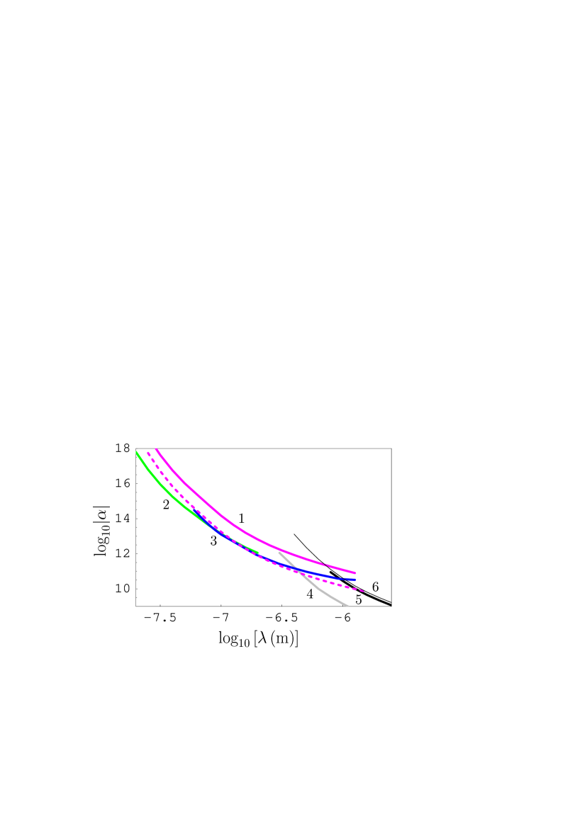
We have obtained the constraints on following from Eqs. (22) and (24) at all separations from 279 to 980 nm where the measurement results were in agreement with the exact theory within the limits of experimental errors. In doing so the following densities of the interacting bodies were used: , , and . The strongest constraints were obtained at nm (in the interaction range from nm to nm), at nm (for nm), and at nm (for m). These constraints are shown as line 1 in Fig. 2, where the regions of -plane above each line are prohibited and below each line are allowed by the results of the respective experiments. For comparison purposes, in the same figure we show constraints on obtained from the measurement of the equivalent Casimir pressure between two parallel plates by means of micromechanical torsional oscillator with a flat plate 19 ; 20 (line 2) and from the Casimir-less experiment 18 (line 3). Line 4 shows constraints obtained 28a from the experiment 29 with torsion pendulum. The constraints obtained from a more recent experiment with torsion pendulum 21 are shown by line 5. Finally, line 6 shows the constraints obtained in Ref. 13a from the measurement of the thermal Casimir-Polder force 29a . It is pertinent to note that both experiments 29 ; 21 performed with a torsion pendulum exploited spherical lenses of more than 10 cm radii of curvature and used the simplified formulation of the PFA (5) to compare the measured Casimir force with theory. Recently it was shown, however, that for lenses of centimeter-size radii of curvature, Eq. (5) is not applicable for the calculation of the Casimir force due to surface imperfections, such as bubbles and pits, which are invariably present on the surfaces of large lenses 30 ; 31 . Because of this, the constraints on shown by the lines 4 and 5 invite further investigation and check.
As can be seen in Fig. 2, the constraints shown by line 1 are a bit weaker than the constraints shown by lines 2 and 3. At m, where the minimum difference between the constraints shown by lines 2 and 3 from the one hand and line 1 from the other hand is achieved, our constraint (line 1) is weaker by a factor of 2.4. This is explained by the smaller density of Si in comparison with the density of Au deposited on both test bodies in the experiments of Refs. 18 ; 19 ; 20 . At the same time, line 1 in Fig. 2 is in very good qualitative agreement with lines 2 and 3 and provides additional confirmation to previously obtained constraints shown by lines 2 and 3.
The above constraints were obtained from Eq. (22) using the exact formulas (24), (10) for the gradient of the Yukawa force. It is interesting to compare them with constraints obtained using a more simple Eq. (20) for the gradient of the Yukawa force using the PFA. To give a few examples, the maximum allowed values of computed at several interacting ranges using the exact gradient of the Yukawa force and the gradient of the Yukawa force calculated within the PFA are the following:
| , | , | , |
| , | , | , |
| , | , | . |
It is seen that under condition (12) the application of the PFA to calculate the Yukawa force results in almost the same strength of constraints as obtained using the exact Yukawa interaction. This provides one more confirmation to the conclusion of Refs. 26 ; 28 that in its application range the PFA is well applicable for calculation of both the Casimir and Yukawa-type forces.
We emphasize that the experiment of Ref. 17 under consideration here leads to competitive constraints on the parameters of Yukawa-type interaction over a very wide interaction range from 30 nm to m. This experiment alone covers the interaction ranges of two earlier performed experiments of Refs. 19 ; 20 (the obtained constraints are shown by line 2) and of Ref. 18 (constraints of line 3). If the material of the corrugated plate (Si) were replaced by Au, the constraints shown by the dashed line in Fig. 2 would be obtained. These constraints are stronger by a factor of than the constraints of line 1. Within some interaction ranges the dashed line also demonstrates stronger constraints than those shown by lines 3, 5, and 6. Thus, at m the constraint shown by the dashed line is by a factor 3.8 stronger than the constraints shown by lines 3 and 5. At m the dashed line gives a constraint which is stronger by a factor 3.4 than that shown by lines 3 and 6.
The above results demonstrate that the experiment of Ref. 17 has considerable opportunity for obtaining constraints on non-Newtonian gravity. Further strengthening of constraints by means of this experiment can be achieved by decreasing the experimental errors and increasing the accuracy of computations of the Casimir force in the framework of the exact theory.
V Conclusions and discussion
In the foregoing we have obtained constraints on the parameters of Yukawa-type corrections to Newtonian gravity which follow from the measurements of the gradient of the Casimir force between an Au-coated sphere and a corrugated Si plate 17 . For this purpose the exact expression for the gradient of the Yukawa force which acts in the experimental configuration of a sphere interacting with a plate covered with trapezoidal corrugations was derived. The expression obtained was compared with that derived using the PFA. The constraints on non-Newtonian gravity were obtained from the measure of agreement between the experimental results and the exact theory of the Casimir force.
According to our results, the obtained constraints are only a bit weaker than those derived from the two different experiments using both Au-coated test bodies 18 ; 19 ; 20 . They cover an extremely wide interaction range from 30 nm to 1260 nm. The same constraints are obtained if the gradient of the Yukawa force were computed using the PFA. This confirms the result of Refs. 26 ; 28 that within its application range the PFA is well applicable to the calculation of the Yukawa-type force.
Some ways of how to strengthen the obtained constraints on the parameters of Yukawa-type interaction using the corrugated surfaces are proposed. It is shown that the use of Au corrugated plate with the same experimental parameters as for a Si plate in Ref. 17 would lead to constraints several times stronger than the ones obtained from the experiments of Refs. 18 ; 19 ; 20 ; 21 ; 29a . Further strengthening is possible at the expense of a decrease of errors in the force measurement and widening the separation interval where the experimental data are in agreement with theoretical results.
Acknowledgments
The authors were supported by CNPq (Brazil). G. L. K. and V. M. M. are grateful to the Federal University of Paraíba, where this work was performed, for kind hospitality.
References
- (1) E. Fischbach and C. L. Talmadge, The Search for Non-Newtonian Gravity (Springer, New York, 1999).
- (2) V. M. Mostepanenko and I. Yu. Sokolov, Phys. Rev. D 47, 2882 (1993).
- (3) I. Antoniadis, N. Arkani-Hamed, S. Dimopoulos, and G. Dvali, Phys. Lett. B 436, 257 (1998).
- (4) N. Arkani-Hamed, S. Dimopoulos, and G. Dvali, Phys. Lett. B 429, 263 (1998).
- (5) N. Arkani-Hamed, S. Dimopoulos, and G. Dvali, Phys. Rev. D 59, 086004 (1999).
- (6) E. G. Floratos and G. K. Leontaris, Phys. Lett. B 465, 95 (1999).
- (7) A. Kehagias and K. Sfetsos, Phys. Lett. B 472, 39 (2000).
- (8) E. G. Adelberger, B. R. Heckel, C. W. Stubbs, and W. F. Rogers, Ann. Rev. Nucl. Part. Sci. 41, 269 (1991).
- (9) E. G. Adelberger, B. R. Heckel, and A. E. Nelson, Ann. Rev. Nucl. Part. Sci. 53, 77 (2003).
- (10) G. L. Klimchitskaya, U. Mohideen, and V. M. Mostepanenko, Rev. Mod. Phys. 81, 1827 (2009).
- (11) M. Bordag, G. L. Klimchitskaya, U. Mohideen, and V. M. Mostepanenko, Advances in the Casimir Effect (Oxford University Press, Oxford, 2009).
- (12) H.-C. Chiu, G. L. Klimchitskaya, V. N. Marachevsky, V. M. Mostepanenko, and U. Mohideen, Phys. Rev. B 80, 121402(R) (2009).
- (13) H.-C. Chiu, G. L. Klimchitskaya, V. N. Marachevsky, V. M. Mostepanenko, and U. Mohideen, Phys. Rev. B 81, 115417 (2010).
- (14) V. B. Bezerra, G. L. Klimchitskaya, V. M. Mostepanenko, and C. Romero, Phys. Rev. D 81, 055003 (2010).
- (15) S. G. Karshenboim, Phys. Rev. D 81, 073003 (2010).
- (16) R. S. Decca, E. Fischbach, G. L. Klimchitskaya, D. E. Krause, D. López, and V. M. Mostepanenko, Phys. Rev. A 82, 052515 (2010).
- (17) G. L. Klimchitskaya and C. Romero, Phys. Rev. D 82, 115005 (2010).
- (18) Y. Bao, R. Guérout, J. Lussange, A. Lambrecht, R. A. Cirelli, F. Klemens, W. M. Mansfield, C. S. Pai, and H. B. Chan, Phys. Rev. Lett. 105, 250402 (2010).
- (19) R. S. Decca, D. López, E. Fischbach, D. E. Krause, and C. R. Jamell, Phys. Rev. Lett. 94, 240401 (2005).
- (20) R. S. Decca, D. López, E. Fischbach, G. L. Klimchitskaya, D. E. Krause, and V. M. Mostepanenko, Phys. Rev. D 75, 077101 (2007).
- (21) R. S. Decca, D. López, E. Fischbach, G. L. Klimchitskaya, D. E. Krause, and V. M. Mostepanenko, Eur. Phys. J. C 51, 963 (2007).
- (22) H. B. Chan, Y. Bao, J. Zou, R. A. Cirelli, F. Klemens, W. M. Mansfield, and C. S. Pai, Phys. Rev. Lett. 101, 030401 (2008).
- (23) B. V. Derjaguin, Kolloid. Z. 69, 155 (1934).
- (24) J. Błocki, J. Randrup, W. J. Swiatecki, and C. F. Tsang, Ann. Phys. (N.Y.) 105, 427 (1977).
- (25) E. M. Lifshitz and L. P. Pitaevskii, Statistical Physics, Part. II (Pergamon Press, Oxford, 1980).
- (26) Handbook of Optical Constants of Solids, ed. E. D. Palik (Academic, New York, 1985).
- (27) F. Chen, U. Mohideen, G. L. Klimchitskaya, and V. M. Mostepanenko, Phys. Rev. A 74, 022103 (2006).
- (28) F. Chen, G. L. Klimchitskaya, V. M. Mostepanenko, and U. Mohideen, Phys. Rev. Lett. 97, 170402 (2006).
- (29) T. Emig, R. L. Jaffe, M. Kardar, and A. Scardicchio, Phys. Rev. Lett. 96, 080403 (2006).
- (30) E. Fischbach, G. L. Klimchitskaya, D. E. Krause, and V. M. Mostepanenko, Eur. Phys. J. C 68, 223 (2010).
- (31) R. S. Decca, E. Fischbach, G. L. Klimchitskaya, D. E. Krause, D. López, and V. M. Mostepanenko, Phys. Rev. D 79, 124021 (2009).
- (32) M. Bordag, B. Geyer, G. L. Klimchitskaya, and V. M. Mostepanenko, Phys. Rev. D 58, 075003 (1998).
- (33) S. K. Lamoreaux, Phys. Rev. Lett. 78, 5 (1997); 81, 5475(E) (1998).
- (34) M. Masuda and M. Sasaki, Phys. Rev. Lett. 102, 171101 (2009).
- (35) J. M. Obrecht, R. J. Wild, M. Antezza, L. P. Pitaevskii, S. Stringari, and E. A. Cornell, Phys. Rev. Lett. 98, 063201 (2007).
- (36) G. L. Klimchitskaya and V. M. Mostepanenko, e-print arXiv:1010.2216v1.
- (37) V. B. Bezerra, G. L. Klimchitskaya, U. Mohideen, V. M. Mostepanenko, and C. Romero, Phys. Rev. B 83, 075417 (2011).