Highly efficient second-harmonic generation from indefinite epsilon-near-zero slabs of subwavelength thickness
Abstract
We theoretically predict efficient optical second-harmonic generation (SHG) from a few hundred nanometer thick slab consisting of a quadratic nonlinear anisotropic medium whose linear principal permittivities are, at the fundamental wavelength, very small and have different signs (indefinite medium). We show that, by illuminating the slab with a p-polarized fundamental wave (with intensity of a few ), a highly efficient scattering of the second-harmonic field occurs when the conditions of linear complete slab transparency for the fundamental wave are met. The high efficiency of the SHG process, stems from the large non-plasmonic enhancement of the longitudinal field, perpendicular to the slab surface, produced by the very small value of the slab dielectric permittivities. A suitable nano-structured composite is proposed and numerically designed for observing the novel non-phase-matched and highly efficient SHG process from nano-structures.
pacs:
42.65.Ky, 81.05.Xj, 78.67.PtEnhancing optical second-harmonic generation (SHG) KangKa ; Samant is at present one of the most relevant task of nonlinear optics due to the major role played by frequency-doubling in coherent green and blue light sources design Yamada , chemistry CornCo , biosensing Campag , etc. In situations where standard phase-matching or quasi-phase-matching techniques cannot be used, efficient SHG is generally achieved by resorting to specific configurations providing a strong field enhancement such as, for example, resonant microcavities Pelleg ; CaoCao ; LeiLei or photonic crystals Mondia ; Liscid ; Siltan ; ZhaoZa . Analogously, the field enhancement occurring on a rough metal surface due to the excitation of surface plasmon polaritons is responsible for a substantial enhancement of the surface SHG ChenCh . Conceiving subwavelength coherent light sources is a fundamental issue of modern nanophotonics Nakaya ; HsiehH so that achieving SHG from nanostructures is an important target. At the nanometer length scale, the small interaction distances generally entail an highly inefficient SHG so that peculiar mechanisms for locally enhancing the electromagnetic field of the fundamental wave have to be harnessed. As an example, the plasmonic field enhancement Barnes occurring in vicinity of the subwavelength apertures in a metallic film (accompanying the extraordinary linear optical transmission Ebbese ) is responsible for an efficient SHG FanFan ; Lesuff ; KangKK ; SchonS when the holes are filled by a quadratic nonlinear material. Another strong plasmonic field enhancement occurs within spherical nanocavities with dielectric core and plasmonic nanoshell Oldenb so that, if the core is filled with a noncentrosymmetric nonlinear medium, a lager enhancement of the SHG is observed PuPuPu .
In this Letter we theoretically show that a subwavelength thick slab consisting of a quadratic nonlinear medium whose linear permittivities are very small and have different signs is able to provide highly efficient SHG. Properties and applications of epsilon-near-zero materials have recently been proposed both in the linear Silver ; Liuuuu ; Edward ; Alekse ; Nguyen and in the nonlinear regime Powell ; Ciatt1 ; Ciatt2 ; Ciatt3 ; Ciatt4 and indefinite materials SmithS ; LiuLi1 ; Nogino ; LiuLi2 have attracted a good deal of attention as well. Here we point out that, the small value of the dielectric permittivities produces a strong non-plasmonic enhancement of the longitudinal field perpendicular to the slab surface. The field enhancement is simply a consequence of the fact that, in conditions of linear complete slab transparency, the longitudinal fundamental field within the slab across the vacuum-slab interface coincides with the longitudinal field of the incident fundamental wave divided by the very small dielectric permittivity. We predict that the enhanced longitudinal field is responsible for a SHG process with efficiency up to , for impinging optical intensities of a few of .
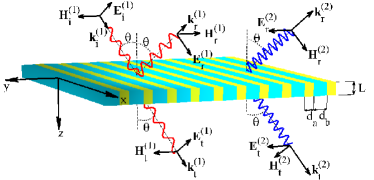
The geometry of the considered SHG setup is sketched in Fig.1 and, labelling hereafter the fundamental and second-harmonic quantities with the superscripts and , we choose and for the two wavelengths. The slab of thickness consists of quadratic nonlinear anisotropic medium whose relative dielectric tensor is (i.e. its principal axes coincide with cartesian axes) and whose second-order nonlinear optical tensor has the only non-vanishing components . Here we choose , and for the only permittivities playing a role in our discussion and for the nonlinear susceptibility (see below for a possible composite medium exhibiting these properties). The slab is illuminated by a plane fundamental wave (FW) with incidence angle and with its electric field polarized in the plane of incidence (p-polarization) so that the reflected (r) and transmitted (t) plane FWs are p-polarized as well. The slab also scatters reflected (r) and a transmitted (t) plane second harmonic waves (SHW) whose electric fields are polarized perpendicular to the plane of incidence (s-polarization), as a consequence of the chosen anisotropic quadratic nonlinearity (see Fig.1 for the definitions of the field amplitudes and wave vectors).
As a prelude to the analysis of the SHG process, it is worth discussing the linear slab behavior observable when the optical intensity of the incident FW is very small. The linear slab transmissivity is
| (1) |
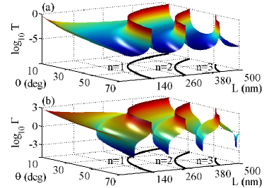
where is the wavevector of the radiation excited within the slab, and . In Fig.2(a) we plot the logarithm of as a function of both the incidence angle and the slab thickness from which we note that the slab is practically always opaque to the considered radiation except for very specific incidence angles (dependent on the slab thickness) for which it is completely transparent. From Eq.(1) it is evident that total transmission occurs if and the ensuing curves of complete transparency are reported with solid lines along the bottom plane of Fig.2(a). Note that if is slightly different from , the denominator in Eq.(1) is dominated by the term containing F (since ) so that the overall transmissivity turns out to be proportional to thus explaining the sharpness of the ridges of T of Fig.2(a) corresponding to complete transparency. In Fig.2(b) we plot the logarithm of the longitudinal field enhancement factor defined as the ratio between the modulus of the field perpendicular to the slab within the medium just across the interface (see Fig.1) and the modulus of longitudinal field of the sole incident FW. Note that, in correspondence of the curves of complete slab transparency, the field enhancement factor is . This is easily understood from one of the field matching condition at the interface (continuity of normal component of the electric displacement field, i.e. ) since, when no reflected wave is generated (i.e. ), so that . We conclude that the considered slab provides a powerful mechanism for attaining a strong enhancement (amounting to ) of the longitudinal field. Note that, for the field enhancement to occur it is essential that is real and this motivates our choice of the permittivities’ signs.
In order to discuss the SHG process we note that the incident p-polarized FW (see Fig.1) produces, within the slab, the transverse magnetic (TM) fundamental field , which, due to the chosen quadratic nonlinearity, couples to the transverse electric (TE) second-harmonic field , (here we have assumed and as time factors for the FW and the SHW fields, respectively). The second-harmonic TE field within the slab matches with the s-polarized reflected and transmitted plane SHWs scattered by the slab Higher . The dielectric slab response is described, in the considered situation, by the electric displacement fields
| (2) |
for the FW and
| (3) |
for the SHW. After setting for the optical intensity of the incident FW, we have numerically solved, for various incidence angles and slab thicknesses , the coupled sets of Maxwell equations (within the slab , where Eqs.(Highly efficient second-harmonic generation from indefinite epsilon-near-zero slabs of subwavelength thickness) and (3) hold) for the FW and the SHW, along with matching conditions (at and ) describing the slab illumination by the sole incident FW. Consequently, we have evaluated the slab efficiencies and of converting the incident FW into reflected (for ) and transmitted (for ) SHWs and their logarithm plots are reported in Fig.3(a) and 3(b), respectively.
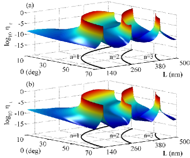
From Fig.3, it is particularly evident that, for the chosen optical intensity of the incident FW, SHG uniquely occurs for specific incident angles and slab thicknesses practically coinciding with those providing linear total transmission of the FW (see the sharp ridges of and approximately located upon the curves ). The physical origin of such phenomenology is easily grasped by noting that SHG is here due to the source term proportional to the components and of Eq.(3), so that, due to the small value of the nonlinear susceptibility , the SHW field scattered by the slab is generally very weak for the chosen impinging optical intensity . In these conditions, the nonlinear terms in Eqs.(Highly efficient second-harmonic generation from indefinite epsilon-near-zero slabs of subwavelength thickness) can be generally neglected so that the FW does not experience the effect of the quadratic nonlinearity and it consequently exhibits the linear behavior of Fig.2.
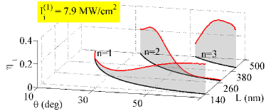
Such an unattractive scenario is fundamentally altered when the conditions of linear complete slab transparency for the FW are met, since the above described enhancement mechanism of the longitudinal field entails an enhancement of the source term so marked to yield efficient SHG (see the sharp ridges of Figs.3(a) and 3(b)). In Fig.4, we plot the values of the above evaluated SHG efficiency exclusively along the curves of linear total transmission of the FW. From Fig.4 we conclude that the proposed mechanism is very efficient, even at the chosen optical intensity since it is characterized by values of the efficiency up to and it takes place in slabs with thickness spanning the subwavelength range . For the sake of completeness, note that the proposed SHG scheme does not rely on the phase-matching condition since the slab SHW wavevector is (in the undepleted pump regime) so that the condition yields the phase matching angle , an angle not playing any special role in the above described process (see Figs.3 and 4).
The above analysis has been carried out for a specific value of . In order to discuss the role played by the FW intensity on the considered SHG process, we have performed further numerical simulations in a thick slab to evaluate the SHG efficiency as a function of the incidence angle and the optical intensity . The logarithm of the obtained is plotted in Fig.5(a) (where the axis is logarithmic) and we have considered a restricted angular range () surrounding the angle which is one the angles (the one belonging to the branch) at which the thick slab is linearly transparent to the FW (see Fig.2). Note that, for angles not close to , the efficiency is a growing function of whereas, at , the efficiency grows for intensities up to , it undergoes a saturation and eventually decreases at higher intensities. For clarity purposes, in Fig.5(b) we plot the efficiency as a function of for . Such a behavior of is evidently a consequence of the fact that, at low optical intensity, the undepleted pump regime rules the phenomenology and provides the growing efficiency whereas, at higher intensities, the full nonlinear regime comes into play where the FW and the SHW experience their mutual nonlinear interaction. It is however remarkable that, in the situation considered in Fig.5, the maximum efficiency is achieved at the intensity (see Fig.5(b)) which is considered to be a small value in a nonlinear optical setup.

In order to prove the feasibility of the above described SHG process, we discuss here the numerical design of a nano-structured composite characterized by the above unconventional features. The slab (see. Fig.1) is manufactured by alternating, along the axis, two kind of layers (labelled with and ) of thicknesses and , respectively. We choose the layers of kind to be filled with alpha-iodic acid (-) crystals with principal axis along the cartesian axis so that the permittivities relevant for our purposes are , , and the non-vanishing components of the second-order nonlinear optical tensor are Dmitri . For the layers of kind we choose a polymer (e.g. poly(methyl methacrylate), PMMA) with permittivities and hosting silver-coated spherical PbSe quantum dots (QDs) with inner radius and outer radius . Exploiting the electrostatic approach of Ref.ZengZe , the structured particle can be described by the equivalent permittivity where , is the Drude-type silver permittivity (, and Scatte ) and is the dielectric permittivity of the considered semiconductor QD (, , FuFuFu and ). Assuming for the volume filling fraction of the QSs embedded in the polymer and using the standard Maxwell Garnett mixing rule for obtaining the effective dielectric permittivity, we obtain, for the layers of kind , and . Since the period is considerably smaller than the two wavelengths, FW and SHW propagating through the slab will experience the effect of a homogeneous medium characterized by the permittivities , , (where and are the layers volume filling fractions), whereas the effective susceptibility is (see Ref.BoydBo for the derivation of these relations). Even though theoretical (note that we have neglected the uncertainties of all the used quantities), the proposed approximate design reveals that, by suitably acting on free parameters (kind of media, QDs volume filling fractions, inversion population factor A, etc.), a medium for observing the proposed efficient SHG can actually be conceived.
In conclusion, we have identified a novel mechanism able to provide a strong field enhancement in anisotropic optical metamaterials having very small cartesian permittivities of different signs. We have showed that, if the slab has a nonlinear quadratic response, the field enhancement is responsible for an efficient SHG process even if the slab thickness is smaller than the wavelength of the SHW. It is worth stressing that the proposed field enhancement mechanism can easily be observed also in setups different from the considered slab. Our findings offers an hitherto unexplored way for achieving efficient SHG from nanostructures and therefore we believe they could pave the way for conceiving a novel generations of nanometric-sized coherent light sources.
References
- (1) H. Z. Kang et al., Opt. Lett. 35, 1605 (2010).
- (2) G. K. Samanta et al., Opt. Lett. 35, 3513 (2010).
- (3) M. Yamada et al., Appl. Phys. Lett. 62, 435 (1993).
- (4) R. M. Corn and D. A. Higgins, Chem. Rev. 94, 107 (1994).
- (5) P. J. Campagnola and L. M. Loew, Nat. Biotechnol. 21, 1356 (2003).
- (6) V. Pellegrini et al., Appl. Phys. Lett. 74, 1945 (1999).
- (7) H. Cao et al., Appl. Phys. Lett. 76, 538 (2000).
- (8) S. Lei et al., Appl. Phys. Lett. 98, 031102 (2011).
- (9) J. P. Mondia et al., Opt. Lett. 28, 2500 (2003).
- (10) M. Liscidi et al., Phys. Rev. Lett. 99, 053907 (2007).
- (11) M. Siltanen et al., Appl. Phys. Lett. 91, 111109 (2007).
- (12) L. Zhao et al., Opt. Comm. 281, 2954 (2008).
- (13) C. K. Chen et al., Phys. Rev. Lett. 46, 145 (1981).
- (14) Y. Nakayama et al., Nature (London) 447, 1098 (2007).
- (15) C. L. Hsieh et al., Opt. Express 17, 2880 (2009).
- (16) W. L. Barnes et al., Phys. Rev. Lett. 92, 107401 (2004).
- (17) T. W. Ebbesen et al., Nature 391, 667 (1998).
- (18) W. Fan et al., Nano Lett. 6, 1026 (2006).
- (19) A. Lesuffleur et al., Appl. Phys. Lett. 88, 261104 (2006).
- (20) M. Kang et al., J. Appl. Phys. 107, 053108 (2010).
- (21) P. Schon et al., Opt. Lett. 35, 4063 (2010).
- (22) S. J. Oldenburg et al., Chem. Phys. Lett. 288, 243 (1998).
- (23) Y. Pu et al., Phys. Rev. Lett. 104, 207402 (2010).
- (24) M. Silveirinha and N. Engheta, Phys. Rev. Lett. 97, 157403 (2006).
- (25) R. Liu et al., Phys. Rev. Lett. 100, 023903 (2008).
- (26) B. Edwards et al., Phys. Rev. Lett. 100, 033903 (2008).
- (27) L. V. Alekseyev et al., Appl. Phys. Lett. 97, 131107 (2010).
- (28) V. C. Nguyen et al., Phys. Rev. Lett 105, 233908 (2010).
- (29) D. A. Powell et al., Phys. Rev. B 79, 245135 (2009).
- (30) A. Ciattoni et al., Phys. Rev. A 81, 043839 (2010).
- (31) A. Ciattoni et al., Opt. Express 18, 11911 (2010).
- (32) A. Ciattoni et al., Opt. Lett. 35, 2130 (2010).
- (33) A. Ciattoni et al., Opt. Express 19, 283 (2011).
- (34) D. R. Smith et al., Phys. Rev. Lett. 90, 077405 (2003).
- (35) Y. Liu et al., Opt. Express 20, 15439 (2008).
- (36) M. A. Noginov et al., Appl. Phys. Lett. 94, 151105 (2009).
- (37) Z. Liu et al., Appl. Phys. Lett. 96, 113507 (2010).
- (38) We are neglecting here the genereration of higher harmonics.
- (39) V. G. Dmitriev, G. G. Gurzadyan and D. N. Nikogosyan, Handbook of Nonlinear Optical Crystals (Springer, Berlin, 1999).
- (40) Y. Zeng et al., Opt. Lett. 35, 1431 (2010).
- (41) Note that the scattering rate is an order of magnitude higher than in bulk silver to allow fro surface scattering in the thin metal shell. See. M. Liu et al., J. Phys. Chem. B 108, 5882 (2004).
- (42) Y. Fu et al., Nano Lett. 8, 1551 (2008).
- (43) R. W. Boyd et al., J. Opt. Soc. Am. B 11, 297 (1994).