Present address: ]Laboratory for Physical Sciences, 8050 Greenmead Drive, College Park, MD 20740.
Spin-memory loss at Co/Ru interfaces
Abstract
We have determined the spin-memory-loss parameter, , by measuring the transmission of spin-triplet and spin-singlet Cooper pairs across Co/Ru interfaces in Josephson junctions and by Current-Perpendicular-to-Plane Giant Magnetoresistance (CPP-GMR) techniques. The probability of spin-memory loss at the Co/Ru interface is . From the CPP-MR, we obtain that is in good agreement with obtained from spin-triplet transmission. For spin-singlet transmission, we have that is different from that obtained from CPP-GMR and spin-triplet transmission. The source of this difference is not understood.
pacs:
75.70.Cn, 85.25.Cp, 73.40.Jn, 74.50.+rI Introduction
Interest in spin-dependent transport in metals and semiconductors has grown rapidly since the discovery of Giant Magnetoresistance (GMR) in the late 1980’s. Optimization of the GMR and other spin-dependent phenomena requires quantitative determination of the parameters characterizing the spin-dependent transport in ferromagnetic (F) and nonmagnetic (N) materials and at their interfaces. Spin-dependent transport phenomena are widespread, and are now known to produce exotic behavior in superconducting/ferromagnetic (S/F) hybrid systems Bergeret:01 as well. The recent experimental demonstration of induced spin-triplet pair correlations in S/F systems Khaire:10 provides further impetus for understanding the spin-dependent transport properties of F and N materials and interfaces.
This paper focuses on the properties of the interface between Co and Ru. The Co/Ru/Co trilayer system exhibits strong oscillatory exchange coupling between the two Co layers, and is known to be a synthetic antiferromagnet (SAF) when the Ru thickness is in the range 0.6 - 0.8 nm.Parkin:90 In our recent work on S/F/S Josephson junctions, we exploited the Co/Ru/Co SAF to form the ferromagnetic (F) core of the junctions. In the SAF, the intrinsic magnetic flux due to the Co domains cancels in the two Co layers, thereby allowing us to produce junctions with uniform current density over large junction areas.Khasawneh:09 Such junctions exhibit textbook-like Fraunhofer patterns when the critical current is plotted vs. the magnetic field applied perpendicular to the current direction – in stark contrast to S/F/S junctions with a single F layer in the place of the SAF.Khasawneh:09 When we placed additional ferromagnetic layers (F’) at either end of our junctions, to form S/F’/SAF/F’/S structures, we observed long-range supercurrents due to the generation of spin-triplet pair correlations in our structures.Khaire:10 Those supercurrents had been predicted to appear in such systems in the presence of non-collinear magnetizations between nearby ferromagnetic layers.Bergeret:01 ; Houzet:07 In our samples the non-collinearity occurs between the F’ and Co layers on either end of the junctions.Khasawneh:11
One issue that has not been resolved is the magnitude of the critical current in our S/F’/SAF/F’/S Josephson junctions, with or without the F’ layers. The critical current in Josephson junctions is often reported as the product of current times normal state resistance, , because that product is normally independent of the junction area. Our junctions exhibit products of order 1-10 for very thin Co layers in the SAF; then decreases exponentially with increasing Co thickness.Khasawneh:09 Josephson junctions of the simpler form S/Co/S have been fabricated and measured by Robinson et al.Robinson:06 Those workers fabricated ultra-small junctions using a focused ion beam technique, and reported products as large as 1 mV, or about 100 times larger than those of our samples. Since the major difference between the samples of Robinson et al. and ours, aside from lateral size, is the presence of the Ru layers in our samples, an obvious candidate to explain our smaller values of is spin-flip scattering in the Ru or at the Co/Ru interface. One goal of this paper is to determine if such scattering can indeed explain the critical current discrepancy noted above.
Spin-flip and spin-orbit scattering are known to be important in the context of GMR.Bass:07 In the most obvious scenario, spin-flip and spin-orbit scattering are sources of spin memory loss in nonmagnetic (N) metals, which lead to the reduction of the GMR signal in F/N/F devices. In a less obvious scenario, spin-flip scattering added intentionally at the outer edges of an N/F/N/F/N device can increase the GMR signal by limiting the spatial extent over which the spin-up and spin-down electrons carry current independently of each other. The same effect occurring in the F materials, however, leads to a reduction in the GMR signal. All of these effects can be understood quantitatively using the Valet-Fert (V-F) equations to describe the spin-dependent transport in the devices.Valet-Fert Within V-F theory, spin memory loss in a bulk metal is characterized by a spin-memory length, . The probability for an electron to lose memory of its spin state while traversing a metal layer of width is then . For an interface between metals A and B, spin memory loss is characterized by a dimensionless parameter , with the associated probability equal to . The main goal of this paper is the determination of from a variety of experiments, both in the context of superconducting systems and in the context of GMR in non-superconducting systems.
II Suppression of Josephson supercurrent by Co/Ru interfaces
In our recent work, we have measured the critical supercurrent, , in Josephson junctions of the form Nb/Cu/F’/Cu/Co/Ru/Co/Cu/F’/Cu/Nb.Khaire:10 ; Khasawneh:11 The inner Co/Ru/Co SAF possesses large exchange energy but very little net magnetic flux. The latter characteristic allows us to obtain reliable estimates of from the measured Fraunhofer patterns.Khasawneh:09 In samples without F’ layers, the large exchange energy leads to a rapid decay of as the Co thickness is increased.Khasawneh:09 This behavior is well-understood,Buzdin:82 and is due to rapid dephasing of the two electrons from the Cooper pair after they enter different spin bands in the Co.Demler:95 In samples with certain specific F’ layers, practically does not decrease with increasing Co thickness,Khaire:10 ; Khasawneh:11 which is a sign that the supercurrent is being carried by spin-triplet rather than spin-singlet pairs.Bergeret:05 Spin-triplet pairs are not present in the original Nb superconductor, but they are produced when the magnetization of the F’ layer is non-collinear with that of the nearest Co layer.Houzet:07 ; Volkov:10 ; Trifunovic:10 The largest spin-triplet supercurrent has been obtained with F’ being a 4-nm-thick layer of PdNi alloy or a 2-nm-thick Ni layer. If the total Co thickness is kept fixed at 20 nm, is enhanced by more than two orders of magnitude by inserting either of those F’ layers.Khasawneh:11
In this work we are interested in how the presence of Co/Ru interfaces affects the magnitude of . Since the supercurrent can be carried either by spin-singlet or spin-triplet pairs, there are two parts to this question. To address how Co/Ru interfaces affect spin-singlet supercurrent, we have fabricated samples without F’ layers, and containing varying numbers of Ru layers. The total Co thickness is kept fixed at 8 nm – large enough to allow subdivision into up to four sub-layers but small enough so as not to suppress below our measurement sensitivity. The Ru layers are always 0.6 nm thick, to optimize antiferromagnetic coupling between the Co layers on either side. For , the central SAF is of the form Co(4)/Ru/Co(4); for it is Co(2)/Ru/Co(4)/Ru/Co(2); and for it is Co(2)/Ru/Co(2)/Ru/Co(2)/Ru/Co(2), where all thicknesses are in nm. This design keeps the net magnetic flux as close to zero as possible for each value of . To address how Co/Ru interfaces affect spin-triplet supercurrent, we have fabricated samples with 4-nm thick PdNi layers as the F’ layers. In these samples the total Co thickness is kept fixed at 20 nm, which is enough to suppress the spin-singlet supercurrent by at least two orders of magnitude relative to the spin-triplet supercurrent.Khaire:10 The ratios of the Co-layer thicknesses are the same as before: for , the central SAF is of the form Co(10)/Ru/Co(10); for it is Co(5)/Ru/Co(10)/Ru/Co(5); and for it is Co(5)/Ru/Co(5)/Ru/Co(5)/Ru/Co(5).

Raw data of vs. applied magnetic field from representative samples of all six types are shown in Fig. 1. The quality of the Fraunhofer patterns is good for all six. The central peaks are shifted from zero by only a few Oersteds, indicating good flux cancellation – i.e. antiferromagnetic alignment of adjacent Co layer magnetizations.
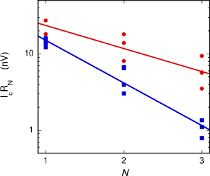
The dependence of on the number of Ru layers is plotted in Fig. 2, both for samples with (red circles) and without (blue squares) F’ layers. In both cases the critical current decreases with increasing number of Ru layers, but surprisingly, the rate of decrease is different in the two cases. Since each Ru layer introduces two additional Co/Ru interfaces, we have fit each set of data to an exponential decay of the form . For the samples without F’ layers, in which we expect the supercurrent to be carried entirely by spin-singlet electron pairs, the value of obtained from the fit is . For the samples with F’ layers and with the thicker Co, in which the supercurrent is carried almost entirely by spin-triplet pairs, the value of obtained from the fit is . We do not understand why spin-singlet pairs appear to be suppressed more than spin-triplet pairs at Co/Ru interfaces.
A number of theoretical works have discussed the effect of spin-dependent, spin-flip, or spin-orbit scattering on the critical current of S/F/S Josephson junctions in various regimes.Demler:95 ; Oh:00 ; Bergeret:03 ; Faure:06 ; Houzet:05 ; Gusakova:06 ; Kashuba:07 ; Bergeret:07 These works address scattering in the bulk of the materials, rather than at interfaces, and most of them address the spin-singlet rather than the spin-triplet supercurrent. Ref. Bergeret:03, is an exception in that it addresses the effect of spin-orbit scattering in the bulk of the F material on both the spin-singlet and spin-triplet supercurrent in S/F/S Josephson junctions. The authors conclude that, for moderate spin-orbit scattering, the spin-triplet component is more sensitive than the spin-singlet component to the spin-orbit interaction. Thus it appears unlikely that spin-orbit scattering is responsible for our experimental observations. There is also a growing literature on spin-dependent boundary conditions at S/F interfaces.Cottet:09 To our knowledge, neither that literature nor the works cited above provide microscopic calculations of spin-memory loss at interfaces, and how such spin-memory loss affects the spin-singlet and spin-triplet supercurrent.
The main conclusion from the results presented in this section is that each additional Ru layer causes only a mild suppression of the critical supercurrent, by factors exp or exp, for the singlet and triplet supercurrents, respectively. This mild suppression is not enough to explain the much larger difference between the values of observed in our large-area samples and those observed in the much smaller samples studied by Robinson et al.Robinson:06
In the next section we discuss an entirely independent way of obtaining , this time by looking at the propagation of spin-polarized electrons in the normal state – without any superconductivity.
III Using Giant Magnetoresistance to estimate
III.1 Important CPP parameters
Before we present the details of the sample structure to determine , we define and quantify the important current-perpendicular-to-plane (CPP) parameters that determine the GMR and how the CPP transport is modeled.
For CPP diffusive transport in ferromagnetic-/nonferromagnetic-metal (F/N) multilayers, the following bulk and interface parameters are important. In the bulk of F, one has the resistivities and that can be combined to give and spin-asymmetry parameter . The arrows () and () correspond to the electron moment being parallel or antiparallel to the moment of F, respectively. For F/N interfaces, one has the interface resistances and that combine to give and spin-asymmetry parameter . For the simple case of no electron-spin flipping in the multilayer, a two current series resistor model (2CSR) can be used to analyze the MR behavior.Lee:93 ; Valet-Fert For the more general case of spin flipping in the bulk of the layers and at the interfaces, the Valet-Fert (VF) modelValet-Fert must be solved numerically to extract important parameters such as Co/Ru.
Our samples contain Nb, Cu, Py (= Permalloy Ni0.8Fe0.2), Co, Ru and FeMn. Our own prior studiesDassonneville:10 ; Fierz:90 ; Bass:99 give the following parameters for these metals: nm; fm2; fm2; nm; ; nm; fm2; . nm; ; ; fm2; ; nm Piraux:98 ; Reilly:98 ; nm; and from ref. Bass:07, , nm; nm and nm.Eid:02 Prior CPP preliminary studies indicated that and fm2.Eid:02 With a Co(3nm)/Ru(0.6nm) multilayer, we obtained a similar value of fm2.Ahn:08 We will refine and later in Section III.C.
III.2 Sample Structures
Two kinds of samples are employed to determine , using CPP-GMR at 4.2K. A CPP double exchange biased spin valve (DEBSV) is used for both structures:Dassonneville:10 Nb(150)/Cu(10)/FeMn(8)/Py(6)/Cu(10)//Cu(10)/ Py(6)/FeMn(8)/Cu(10)/Nb(150), where the thicknesses are in nm and represents the inner sets of layers of the two samples labelled with or 2. The two Py layers are pinned by exchange-bias coupling to the FeMn layers, so that their magnetic moments reverse together at a much higher field than is needed to reverse the overall moment of . Also =10 nm is thick enough to exchange-decouple from the Py layers. To achieve uniform current flow in the CPP geometry, the multilayers are sandwiched between -mm wide, crossed Nb strips, which superconduct at our measuring temperature of 4.2 K. We find the overlap area mm2 through which the CPP current flows by measuring the width of each Nb strip with a Dektak profilometer. The intrinsic quantity for these measurements is AR where R is the CPP resistance. Our sputtering system, sample preparation, and measuring techniques are described in ref. Lee:95, .
has the following structure: [Co(3)/Ru(1.4)/]nCo(3) where ranges from 0 to 8. The 1.4-nm-thickness of the Ru is chosen to cause parallel exchange coupling between the Co layers so that the magnetizations of the Co layers switch as a single unit when a modest in-plane magnetic field is reversed. The CPP-GMR then results from reversal of the moment of from parallel (P) to anti-parallel (AP) to the common direction of the moments of the two Py layers. We measure and see how it changes with , a behavior that depends upon . One of us used an identical sample structure with Ru replaced by Cu to determine .Dassonneville:10
has the following structure: [Co(1.5)/Ru(0.6)/]m[Co(3)/Cu(1.4)/Co(3)/] [Ru(0.6)/Co(1.5)]m where ranges from 0 to 3. The 1.4-nm-thick Cu layer in the middle of the structure exchange couples the moments of the two adjacent Co layers parallel. The 0.6-nm-thick Ru layers couple the adjacent Co-layer moments in an antiparallel state. For example, with , the Co(1.5) layers are antiparallel to the nearest Co(3) layer, and the 1.5-nm-thickness of the outer Co layers ensures that the overall moment of the multilayer is parallel to that of the Co(3) layers. Thus this system will switch as a unit when a modest magnetic field is reversed. As will be explained later in Section III.D., this geometry shows a more sensitive dependence of on for and 3.
III.3 Refinement of and
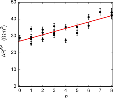
For samples, the slope from a plot of vs can be used to determine . The 2CSR model predicts that slope=. Fig. 3 shows a plot of vs . The least-squares linear fit has a slope of fm2 that gives fm2. This value of just agrees within mutual independent uncertainties with fm2 for nm.Ahn:08 Because the higher interface resistance may be associated with a more completely-formed interface for nm, we will use the value of for -related calculations, and we use the lower value of for the samples where nm.
To refine , we revisit the preliminary analysis in ref. Eid:02, . In Fig. 3 of that publication, is plotted vs. for a multilayer of the form: [Py(6)/Cu(20)/Ru(2)/Co()/Ru(2)/Cu(20)/Py(6)]6. If is negative, there will be value of where positive spin asymmetry in bulk of the Co cancels the negative spin asymmetry of the two Co/Ru interfaces, and =0. The 2CSR model predicts that
| (1) |
A linear fit to vs. gives nm at the point where . Using the value of (since nm here) and the known values of other parameters (except for ), we obtain . This value of will be used in the analysis of our data.
| Magnetic structure for sample | |
|---|---|
| 0 | Cu//Cu//Cu |
| 1 | Cu//Ru//Cu//Ru//Cu |
| 2 | Cu//Ru//Ru//Cu//Ru//Ru//Cu |
| 3 | Cu//Ru//Ru//Ru//Cu//Ru//Ru//Ru//Cu |
III.4 Expected behavior of
To simplify the data analysis that will come later, we present here the expected behavior of for both types of samples using the V-F model. To determine the effect of , we will vary between the extremes of 0 and -0.12. Also we know that ;Dassonneville:10 and, anticipating our result for , here we set, temporarily, .
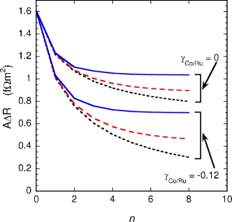
For the samples, Fig. 4 shows the anticipated behavior of vs. for =0 and - 0.12. Here decreases with increasing . In contrast, the Co/Cu system showed increasing with .Dassonneville:10 This difference is due the positive, much larger value of , in comparison to .
The dotted curves are for spin flipping at the Co/Cu interfaces only with no spin flipping elsewhere. The dashed curves show what happens when bulk spin flipping in Co and Ru is added. Finally, the solid curves exhibit the additional effects of having . The transition from the dashed to solid curves at large indicates that, in principle, the effects of finite should be observable in the data. However, the significant dependence of on will likely complicate the extraction of from the data.
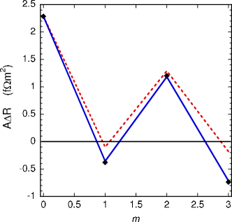
For the samples, Fig. 5 shows the expected behavior of vs. using the V-F model. The lines are for . The dotted lines are for spin flipping only at Co/Cu interfaces and in the bulk of the Co and Ru layers. These dotted lines are hardly changed if the bulk spin flipping is omitted. The solid lines show what happens to when . As anticipated, is most sensitive to for and 3, as explained below. The diamond symbols represent the case where . In contrast to Fig. 3, here is not sensitive to , and this lack of sensitivity will make a determination of more robust. For example, if the calculated value of for and is held fixed as is set to zero, only decreases to 0.31.
Including the Cu layers between the insert and the two Py layers, the sample structure is Cu(10)/[Co(1.5)/Ru(0.6)/]m[Co(3)/Cu(1.4)/Co(3)/] [Ru(0.6)/Co(1.5)]m/Cu(10). This structure is designed to make the major contribution to of the large asymmetry of the Co/Cu interfaces () sensitive to for and 3.
Table 1 shows how the magnetic moments of the two Co(3) () layers are aligned with respect to the Co(1.5) () layers.
For no spin flipping anywhere, the 2CSR model predicts the following behaviors. (a) For and 2, the moments of the outer Co(1.5)/Cu interfaces are parallel to those of the inner Co(3)/Cu interfaces, giving a large positive as seen in Fig. 5. (b) For and 3, the outer Co(1.5)/Cu interfaces are antiparallel to those of the inner Co(3)/Cu interfaces, giving , as seen Fig. 5. The contributions of Co/Ru regions to are included in items (a) and (b), but we clarify next how the 2CSR model applies to these Co/Ru regions. For , the two antiparallel Co/Ru interfaces on each side of a given nm layer together give no contribution to the overall spin asymmetry of the layer and thus do not contribute to . For example, the contributions to of the /Ru/ interfaces are for the left interface and for the right. Since this cancelation is independent of the value of , will not depend on , at least for the case of no spin flipping anywhere. Thus the very weak dependence of upon shown in Fig. 5 is plausible. With and 3, the overall bulk-Co contribution to is equivalent to two Co layers () with 1.5 nm thickness, giving in terms of the 2CSR model that fm2. This positive bulk contribution to is small compared to that for and 2, justifying the statement that for and 3.
For finite with and 3, the spin flipping at the Co/Ru interfaces causes the two outer /Cu interfaces to make a more significant contribution to than the central two /Cu interfaces. Crudely, the two inner /Cu interfaces are becoming ”isolated” by spin flipping from the two outside Py layers. Thus we have , as seen in Fig. 5. For , is even more negative because there are more Co/Ru interfaces between the inner and outer Co/Cu interfaces. Hopefully these negative values of will be seen in the data.
IV Giant Magnetoresistance data
IV.1 raw data
Raw magnetoresistance data for a representative selection of samples with and are shown in Fig. 6. The outer Py layers are pinned in the negative direction in the figure. Hence at negative applied fields , the samples are in the P (low resistance) state, and at positive , the samples are in the AP (high resistance) state. The hysteresis is due to the coercive field of the inner Co/Ru multilayer, which switches sharply as a single block due to the ferromagnetic exchange coupling induced by the 1.4-nm thick Ru layers. The flat parts of the graphs outside the hysteresis region allow precise determination of .

IV.2 raw data
Raw magnetoresistance data for a representative selection of samples with various values of are shown in Fig. 7. Again, the outer Py layers are pinned in the negative direction. A sample with , shown in panel a), exhibits clear switching of the central Co/Cu/Co trilayer, as expected, at 200 Oe. At negative , the sample is in the P (low resistance) state, while at positive , the sample is in the AP (high resistance) state. Note that samples with are similar to samples with , except that the former have Cu rather than Ru separating the two central Co layers. As a result, they have much larger values of because is large and positive whereas is small and negative.

A sample with , shown in panel b), exhibits similar behavior, since for any even value of the outer Co layers are parallel to the central Co layers. The resistance data in the AP state (at Oe) are not quite as flat in this sample as in the sample, so was determined near where is a maximum. Note that the switching field here is approximately twice that for in panel a). So at these higher fields we may be seeing the effects of unpinning of the Py layers that would cause to decrease with increasing field.
The situation is different for samples with odd values of , as shown in panels c) and e) of Fig. 7 for lower fields and panels d) and f) for higher fields. These four panels show that the magnetoresistance is negative, as expected if is finite. is determined from the data near =0 because decreases as becomes more negative. In this decreasing field, those outer thin-Co layers that are antiparallel to the central Co layers are tending to rotate parallel to the central Co and Py layers, moving toward a ”global” parallel state for all of the Co layers. This will decrease . In fact, for , we estimate that will decrease by n for the sample in panel d). The decrease in R seen in panel d) as goes from 0 to Oe is much smaller than this predicted extreme case, so the misalignment of the antiparallel outer Co layers is small but still makes a significant contribution to the magnetoresistance. Thus is important to determine near . is determined in the low-slope region near =+600 Oe, just below the onset of Py-layer unpinning for . As discussed for , increasing will cause those outer thin-Co layers that are antiparallel to the central Co layers to rotate more parallel to the central layers and less parallel to the Py layers. Thus will tend to increase. This means that the actual value of is likely to be less than directly determined from data for = +600 Oe. Thus the magnitude of is underestimated. To make this correction to , one could take the change in as varies from - 600 Oe to 0 Oe and subtract this from the nominal value of . We will analyze the data without this correction and then ask what happens to when this correction is made to the data.
For , making such corrections to is more difficult. As shown in panels e) and f) of Fig. 7, a larger value of is needed to saturate the magnetization of the [Co(1.5)/Ru(0.6)/]3[Co(3)/Cu(1.4)/Co(3)/] [Ru(0.6)/Co(1.5)]3 free layer than for the samples. Thus the ”plateau” region where is evaluated contains a competition between an approach to saturation of the Co-containing multilayer and the unpinning of the Py layers. Thus it is likely that is over estimated, causing the magnitude of to be underestimated. Hence, the experimental values of are less reliable even if the above-mentioned corrections of the previous paragraph were applied to the samples.
V Data analysis and discussion
V.1 data for samples
As we showed in Fig. 5, for samples is not sensitive to . So we analyze the samples first to establish a value that we can compare with that from the Josephson junction studies in Section II. Note that the Josephson junctions and the samples employ the same =0.6 nm thickness, while the samples have =1.4 nm.
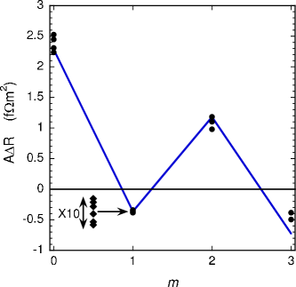
Fig. 8 shows vs. for the samples. The solid lines represent the fit of V-F model to the data only, using and the other parameters presented in Section III.A, and obtaining . The diamond symbols show a detail of the six data points for , where the ordinate is expanded by a factor of ten about the average value of the data. For the = 0 samples where there are no Co/Ru interfaces present, the calculated value of agrees well with the average value of data within mutual uncertainties. This agreement strengthens the argument that the parameters tabulated in Section III.A are relevant to our samples. For , the calculated value of also agrees well with data. For , the experimental value of does not agree very well with its calculated value, as anticipated in the last paragraph of Section IV.B.
If one applies the correction outlined in Section IV.B to the data, only increases to 0.35. Varying by its uncertainty only contributes a uncertainty to , as expected from the discussion of Fig. 5. Including the uncertainty associated with , we obtain a final value of . Interestingly, this value of agrees with those obtained for Co/Cu and Co/Ni interfaces: and .Dassonneville:10 ; Nguyen:10
V.2 data for samples
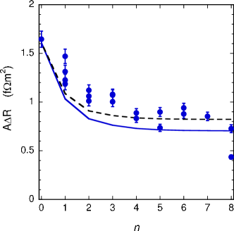
Fig. 9 shows vs. for the samples. The solid curve indicates the expected behavior for the V-F model employing the parameters that were used in the V-F fits to the data in Fig. 8. Although the overall drop in with increasing is reproduced, the fit is not very good especially for small . The dashed curve shows the V-F model fit when and are used, the extreme values allowed by their uncertainties. Most of the rise in is due to the increase in , as expected from the discussion concerning Fig. 4. While this dashed curve fits the larger data pretty well, it still does not fit the low- data for reasons that are not understood. So we rely on the fits to the data of the samples to determine . However, the vs. data for these samples with =1.4 nm was useful in determining so that the value of could be refined (see Section III.C).
VI Conclusions
The interfacial spin-memory loss parameter, , has been determined in two ways: measuring the transmission of spin-triplet and spin-singlet Cooper pairs across Co/Ru interfaces in Josephson junctions, and using Current-Perpendicular-to-Plane Giant Magnetoresistance techniques (CPP-MR). For spin-triplet transmission, we obtain in comparison to from CPP-MR measurements. These two values of are in excellent agreement. They also agree with values obtained for Co/Cu and Co/Ni interfaces: and .Dassonneville:10 ; Nguyen:10 It is hoped that this agreement will stimulate more theoretical work to establish the source(s) of spin-memory loss at F/N interfaces. The most likely contributions include spin-orbit and interfacial spin-disorder scattering.Fert-Lee:96 ; Tang-Wang:08 Also we refined an earlier estimate of the Co/Ru interfacial scattering asymmetryEid:02 and obtained . For spin-singlet transmission across the Co/Ru interface, we obtained that is about a factor of two larger than from spin-triplet and CPP-MR measurements. This factor-of-two enhancement in is not understood and will hopefully encourage further theoretical work.
Acknowledgments: We thank S. Bergeret for helpful discussions, R. Loloee and B. Bi for technical assistance, and use of the W.M. Keck Microfabrication Facility. This work was supported by the U.S. Department of Energy under grant DE-FG02-06ER46341.
References
- (1) F.S. Bergeret, A.F. Volkov, and K.B. Efetov, Phys. Rev. Lett. 86, 4096 (2001).
- (2) T.S. Khaire, M.A. Khasawneh, W.P. Pratt Jr. and N.O. Birge, Phys. Rev. Lett. 104, 137002 (2010).
- (3) S.S.P. Parkin, N. More, and K.P. Roche, Phys. Rev. Lett. 64, 2304 (1990).
- (4) M.A. Khasawneh, W.P. Pratt, and N.O. Birge, Phys. Rev. B 80, 020506(R) (2009).
- (5) M. Houzet and A.I. Buzdin, Phys. Rev. B 76, 060504(R) (2007).
- (6) M.A. Khasawneh, T.S. Khaire, C. Klose, W.P. Pratt, and N.O. Birge, Supercond. Sci. Technol. 24, 024005 (2011).
- (7) J.W.A. Robinson, S. Piano, G. Burnell, C. Bell and M.G. Blamire, Phys. Rev. Lett. 97, 177003 (2006).
- (8) J. Bass and W.P. Pratt Jr., J. Phys. Cond. Matt. 19, 183201 (2007) and references therein.
- (9) T. Valet and A. Fert, Phys. Rev. B 48, 7099 (1993).
- (10) A. Buzdin, L.N. Bulaevskii, and S.V. Panyukov, JETP Lett. 35, 178 (1982).
- (11) E.A. Demler, G.B. Arnold, and M.R. Beasley, Phys. Rev. B 55, 15174 (1997).
- (12) F.S. Bergeret, A.F. Volkov, and K.B. Efetov, Rev. Mod. Phys. 77, 1321 (2005).
- (13) A.F. Volkov and K.B. Efetov, Phys. Rev. B 81, 144522 (2010).
- (14) L. Trifunovic and Z. Radovic, Phys. Rev. B 82, 020505(R) (2010).
- (15) S. Oh, Y.-H. Kim, D. Youm, and M.R. Beasley, Phys. Rev. B 63, 052501 (2000).
- (16) F.S. Bergeret, A.F. Volkov, and K.B. Efetov, Phys. Rev. B 68, 064513 2003!
- (17) M. Fauré, A.I. Buzdin, A.A. Golubov, and M.Yu. Kupriyanov, Phys. Rev. B 73, 064505 (2006).
- (18) M. Houzet, V. Vinokur, and F. Pistolesi, Phys. Rev. B 72, 220506(R) (2005).
- (19) D.Yu Gusakova, A.A. Golubov, and M.Yu. Kupriyanov, JETP Lett. 83, 418 (2006).
- (20) O. Kashuba, Ya.M. Blanter, and V.I. Fal ko, Phys. Rev. B 75, 132502 (2007)
- (21) F.S. Bergeret, A.F. Volkov, and K.B. Efetov, Phys. Rev. B 75, 184510 (2007).
- (22) See A. Cottet, D. Huertas-Hernando, W. Belzig, and Yu.V. Nazarov, Phys. Rev. B 80, 184511 (2009), and references therein.
- (23) S.-F. Lee, W. P. Pratt Jr., Q. Yang, P. Holody, R. Loloee, P. A. Schroeder, and J. Bass, J. Magn. Magn. Mat. 118, L1 (1993).
- (24) B. Dassonneville, R. Acharyya, H.Y.T. Nguyen, R. Loloee, W.P. Pratt Jr., and J. Bass, Appl. Phys. Lett. 96, 022509 (2010).
- (25) C. Fierz, S.-F. Lee, W.P. Pratt, Jr., P.A. Schroeder, and J. Bass), J. Phys. Cond. Mat: 2, 970 (1990).
- (26) J. Bass and W.P. Pratt Jr., J. Magn. Magn. Mat. 200, 274 (1999).
- (27) L. Piraux, S. Dubois, A. Fert, and L. Belliard, Euro. Phys. J. B, 4, 413 (1998).
- (28) A.C. Reilly, W.-C. Chiang, W.-J. Park, S.Y. Hsu, R. Loloee, S. Steenwyk, W.P. Pratt Jr. and J. Bass, IEEE Trans. Magn. 34, 939 (1998).
- (29) K. Eid, R. Fonck, M. AlHaj Darwish, J. Bass, and W. P. Pratt Jr., J. Appl. Phys. 91, 8102 (2002).
- (30) Chiyui Ahn, K-H Shin, and W. P. Pratt, Jr., Appl. Phys. Lett. 92, 102509 (2008).
- (31) S.F. Lee, Q. Yang, P. Holody, R. Loloee, J.H. Hetherington, S.Mahmood, B. Ikegami, K. Vigen, L.L. Henry, P.A. Schroeder, W.P. Pratt Jr., and J. Bass, Phys. Rev. B 52, 15426 (1995).
- (32) H. Y. T. Nguyen, R. Acharyya, E. Huey, B. Richard, R. Loloee, W. P. Pratt, Jr., J. Bass, S. Wang and K. Xia, Phys. Rev. B 82, 220401(R)(2010).
- (33) A. Fert and S.F. Lee, Phys. Rev. B 53, 6554 (1996).
- (34) L. Tang and S. Wang, Mod. Phys. Lett. B 22, 2553 (2008).