Experimental demonstration of Aharonov-Casher interference in a
Josephson junction circuit
Abstract
A neutral quantum particle with magnetic moment encircling a static electric charge acquires a quantum mechanical phase (Aharonov-Casher effect). In superconducting electronics the neutral particle becomes a fluxon that moves around superconducting islands connected by Josephson junctions. The full understanding of this effect in systems of many junctions is crucial for the design of novel quantum circuits. Here we present measurements and quantitative analysis of fluxon interference patterns in a six Josephson junction chain. In this multi-junction circuit the fluxon can encircle any combination of charges on five superconducting islands, resulting in a complex pattern. We compare the experimental results with predictions of a simplified model that treats fluxons as independent excitations and with the results of the full diagonalization of the quantum problem. Our results demonstrate the accuracy of the fluxon interference description and the quantum coherence of these arrays.
The formation of macroscopically large coherent states in systems with many unquenched degrees of freedom tests our understanding of quantum mechanics and it is essential for quantum computation. One of the most striking consequences of such coherence are interference patterns that are expected to appear when a charged particle encircles a magnetic flux (Aharonov-Bohm effectAharonov1959 ) or when a flux encircles a charge (Aharonov-Casher effectAharonov1984 ). The quantum coherence implied by these effects is a fragile phenomenon which is easily destroyed by uncontrolled degrees of freedom. In an ideal Josephson junction array most microscopic degrees of freedom are quenched by electron pairing into Cooper pairs; the only remaining degrees of freedom are the phase of the order parameter on each island or the charge conjugated to it. Observation of the interference provides the evidence of the full control of the quantum system in the ground state. In Josephson junction arrays it proves the irrelevance of the uncontrolled degrees of freedom such as two level systems, non-equilibrium quasi-particles, etc.
Aharonov-Bohm (AB) effect in small and large Josephson arrays is a very well established phenomenon: in the former it leads to critical current oscillations in SQUIDsClarkeBraginskiBook , in the latter it results in a complicated magnetic field dependence with many peaks at commensurate fieldsVoss1982 ; Voss1983 ; Chen1996 ; Fazio2001 . The experimental confirmation of its dual, the Aharonov-Casher (AC) effect, is less clear. It was observed for small Josephson circuits where vortices moved in a ring encircling a single chargeElion1993 . However, large arrays studied in a number of works show the appearance of the intermediate “normal” phase of the arrays which is characterized by a non-zero resistanceVanderZant1993 ; Chen1996 ; SerretThesis2002 . Non-zero resistance implies that the fluxon motion is dissipative; this excludes quantum coherence. It is very important to establish the presence or absence of this dissipation and its possible origin in well controlled medium size arrays. This is the main goal of our work.
The duality of AB and AC effects can be illustrated by analyzing the quantum mechanical phase resulting from the braiding of particle with charge and a neutral particle with magnetic moment . If the charged particle is at rest while the neutral one moves, the former generates an electrical field at the position of the latter that gives the interaction energy . Conversely, the magnetic moment at rest generates a vector potential at the position of the moving charge, that gives the interaction energy In either case, the acquired phase is given by the time integral of the interaction energy. In case of the moving charge, this phase is (AB effect); in case of a moving magnetic moment this phase is (AC effect). Experimentally the former was first observed 50 years ago as an electron interference pattern in magnetic field Chambers1960 ; the latter was measured with percent accuracy in neutron and atomic interferometry experiments Cimmino1989 ; Sangster1993 . In Lorentz invariant systems of neutral and charged particles the distinction between the two effects is impossible. What seems as AB effect for the observer in the rest frame of the neutral particle becomes AC effect for the observer in the rest frame of the charged particle. In solid state devices these effects are distinguishable because the rest frame is fixed by the device, and therefore the observation of AB interference does not imply the one of AC and vice versa. Because uncontrolled degrees of freedom turn out to be mostly electric charges (either background charges or non-equilibrium quasi-particles in superconductors), experimentally it is difficult to remain in the rest frame of the charge and, consequently, the observation of the AC effect is much more challenging.
A Josephson junction circuit can be described either in terms of the superconducting phase or in terms of the charges of its islands. If the charging energy is larger than the Josephson energy , Cooper pairs are almost localized. The dynamics of a Josephson junction array can be viewed as due to the rare motion of these pairs. In the opposite limit the charge is delocalized and the array dynamics can be viewed as due to rare phase slips resulting in the motion of fluxons. The nature of the elementary excitations does not preclude however the description of the circuit in the charge (or phase) basis. The elementary excitations only become more complicated objects for in the charge basis or for in the phase basis.
In the following, we analyze the ground state properties of a 6 Josephson junction chain as a function of the gate voltage that induces polarization charges for . Because in this regime the individual excitations are fluxons, the properties of the circuit are due to the interference between phase-slips on different junctions. The interference pattern is due to the charges induced on the array islands which is exactly AC effect. The difference between the longer chain (of six junctions) studied here and the previous worksElion1993 ; Friedman2002 is that fluxons can take one of the six possible routes resulting in a much more complicated interference. In the following we compute the expected properties of the array assuming that phase slips are independent excitations. Because this assumption might be questioned for we have also performed the complete diagonalization of the Hamiltonian. Finally we compare the results of both approaches to the measured data. Our main conclusion is that the phase slip approximation provides a semi-quantitative description of the data in this regime and that the observed interference pattern evidences the quantum coherent dynamics of our relatively large circuits.
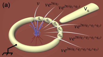
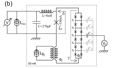
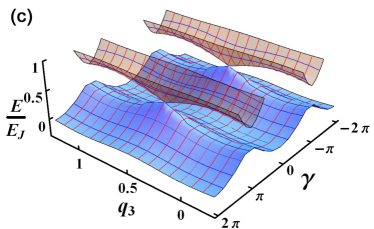
Fig.1a shows an idealized view of our circuit: a superconducting ring containing five islands connected by Josephson junctions. A gate voltage induces the charge frustration on the i-th island. Here are static offset charges. The couplings to the gate electrode are not equal for all islands and induce a general charge configuration , expressed in units of . White traces in Fig.1a represent six possible paths for a fluxon to cross the ring, through one of the six Josephson junctions. The probability of this event is given by the quantum phase-slip amplitude of a single junction. contains an AC phase-factor depending on the islands charges (see eq. (1) and (2)). The ground state of the SQUID chain depends on the Coherent Quantum Phase-Slip (CQPS) amplitude that results from the macroscopic interference of six fluxons. The CQPS amplitude, , is obtained by summing up all phase-slip amplitudes on the junctions Matveev2002 (for computation details see the Supplementary Information text):
| (1) |
Here is the magnitude of the phase-slip amplitude for a single Josephson junction. In the quasi-classical approximation, valid at , it isLikharev1985 :
| (2) |
The first two energy levels of a Josephson junction chain are shown in Fig. 1c. These energy levels have been calculated by diagonalizing the Matveev-Larkin-Glazman (MLG) tight-binding Hamiltonian Matveev2002 :
| (3) |
Here is the energy of the state of the chain polarized at phase and is the quantum variable that counts the number of vortices having crossed the chain through one of the junctions. The model (3) makes two important assumptions: the quantum phase slips on different junctions lead to the same quantum states and these tunneling processes are independent events. As it can be seen from eq. (1), the AC interference of CQPS is an intrinsically periodic effect.
In our sample, each junction of the chain is realized by a SQUID (see Fig. 1b) to enable tunable Josephson coupling . Consequently we can control in-situ the strength of the quantum phase slip amplitude through the magnetic flux . To measure the CQPS effect on the ground state of a Josephson junction chain, we have shunted the chain by a large read-out junction (see Fig. 1b, Vion2002 and Pop2010 ). The flux in the superconducting loop containing the read-out junction and the chain, enables the control of the bias phase over the chain. is the phase difference on the read-out junction.
We have measured the switching current (see the Methods section) of the entire Josephson junction circuit containing both the chain and the read-out junction. We start by presenting the gate-voltage dependence of the switching current (Fig. 2) for small variations of the gate voltage (so that ) and for two different ratios of . As the central coupling is times larger than any other coupling, the gate voltage only polarizes the middle island. The values of the island charges result from the combined effect of the gate voltage and off-set charges. In the particular case of our circuit, the latter vary randomly within a time scale of min in average, enabling the measurement of a single charge configuration during a gate voltage scan that takes minutes. Thus, by repeating the same voltage sweep, we measure different charge configurations. The results presented in Fig. 2 were post-selected from a large set of data, of about runs by choosing the largest observed switching current oscillations. The largest oscillations displayed in Fig. 2 correspond to a particularly simple case in which all charges, except the one on the middle island are close to zero: . Notice that the ab-initio probability to produce this charge configuration is which translates into 6 configurations out of 3000, so its observation supports the assumption of random charge distribution.
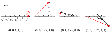
The charge frustration on the middle island introduces a geometrical phase shift between the three CQPS occurring on the junctions at the left side of the middle island and the three CQPS on the junctions at the right of the middle island. This phase shift between the different CQPS is graphically represented for several charge configurations in Fig. 2a. In this regime the total CQPS amplitude (eq. 1) as a function of gate voltage becomes:
| (4) |
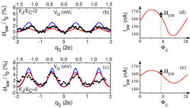
The phase-slip amplitude is expected to vanish completely for the charge configuration while the maximum value is obtained for the charge configuration . The red line of Fig. 2 shows the corresponding theoretical calculation using the CQPS model (3),(4). Around the charge configuration we expect a complete suppression of the total phase-slip amplitude (see Fig. 2a), hence an increase of the supercurrent through the chain. For , the change in the measured switching current due to the full suppression of CQPS is 1nA, which represents of the critical current of one SQUID, . Increasing the CQPS-amplitude by decreasing the ratio to a value of , the oscillation amplitude of the switching current increases to which represents of (see Fig. 2c).
We now turn to the discussion of more complex interferences of CQPS realized by increasing the gate voltage () that leads to the polarization of the islands next to the central island. In Fig. 3c we show two interference patterns that were post-selected from a total of 200 curves. Again, the selection criteria was the maximum observed switching current amplitude. In the following we show that these measured patterns can be understood by considering charge configurations in which only : . The corresponding ab-initio probability is which translates into curves out of the measured .
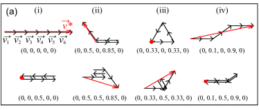
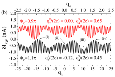
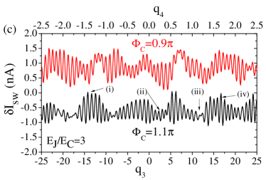
The charge frustration on the middle, the second and the fourth islands introduces geometrical phase shifts between the CQPS of the second, third and forth junctions. Fig. 3a show the corresponding CQPS amplitudes as vectors in the complex plane for several charge configurations. The resulting switching current oscillations , presented in Fig. 3b, show a complex pattern, composed of a fast harmonic arising from the strong coupling and a slower evolving envelope due to the weaker and couplings (see Table 1). In Fig. 3c we show the measured interference patterns for two different phase biases of the Josephson junction chain; these biases were chosen close to in order to maximize the response of the chain. For the top curves in Fig. 3b and c we polarized the chain at so we expect the switching current to increase when the phase slips are suppressed. Similarly, for the bottom curves, where , we expect the switching current to decrease when the chain becomes classical. The exact shape of the oscillations envelope depends on the configuration of the offset charges . For the two calculated curves we have chosen the offset charges configurations that give the best fit the experimental data. The exact values of the fit parameters are shown in table. 1.
The qualitative behavior of the interference pattern agrees perfectly with the theoretical expectations based on the simple picture of addition of complex amplitudes. Using the fitted values of we evaluate the gate voltages corresponding to the special charge configurations shown in Fig. 3a and indicated them on the measured and calculated curves. For instance, point corresponds to the configuration where all charges are zeros, the same configuration that was realized in measurements displayed in Fig. 2a at . Notice that in the measurements presented in Fig. 3 its position is shifted along the x axis by the offset charges on the islands and . Because for arbitrary values of the total CQPS amplitude is less than , one expects that maximal oscillations as a function of occur around point (see Fig. 3a). Indeed, next to this point, the switching current oscillations have the largest amplitude. The chain goes from the perfectly coherent phase-slips regime at , where the switching current is minimum (the zero level in Fig. 2b and c), to the maximally dephased configuration at when the phase slips are canceled, the chain is almost classical and the critical current is enhanced. Point corresponds to opposite limit in which the oscillations are strongly suppressed due to interference induced by non-zero charges at Working point shows the situation when the total CQPS amplitude is suppressed at and it never reaches the maximum for any value of (see Fig. 3a). In this case we expect small oscillations of that reach the maximum supercurrent for the classical chain. The case of shows that it is not necessary to have the CQPS perfectly aligned as in in order to have a large amplitude of oscillations. As expected, the oscillations around are comparable in amplitude to the ones around point .
The Aharonov-Casher interference of phase slips is expected to be a periodic effect. In general, random quasi-particle poisoning is a severe problem for the observation of the interference effect as the contamination reduces the accessible charge interval from to . As a consequence, the amplitude of the oscillations in the interference pattern is significantly reduced by quasi-particle poisoningElion1993 . In our case we observe the quasi-particle poisoning by the appearance of a periodicity in the vs. oscillations for temperatures above . At base temperature we scan the full charge space interval enabling the observation of complete destructive CQPS interference (see Fig. 2). Furthermore, spectroscopy measurements of propagative modes in long SQUID chains PopThesis2011 independently confirms the value of the gate capacitance , corresponding to a periodic vs. curve at low temperature.
As can be seen from the periodic dependence of the measured switching current, the island charge configuration does not change significantly during the measurement. Although each measurement point implies repeated switchings into the dissipative state of the junctions, where large numbers of quasi-particles are excited, after the circuit relaxes back to the dissipationless state, the charge configuration is stable enough in order to enable the measurement of the interference pattern. We have directly measured the frequency of random charge jumps by repeating the same measurement several times and we observe a typical time of minutes between changes in the island charge configuration. This time interval is sufficient in our case as it enables the measurement of several hundreds of experimental data points.
It is well established that slow drift of charge induced by fluctuating TLS leads to at time scales of minutesZimmerman2008 . A significant charge drift at this and smaller time scales is attributed to non-equilibrium quasi-particles jumping between the islandsMartinis2009 ; the equilibration of these quasi-particles is made difficult by their localization in subgap statesFaoro2008 . Surprisingly, the time scales of these jumps might be dramatically different even in similar devices. Charge fluctuation times, similar to the one observed here, have been reported previously in small highly resistive Josephson islandsMaisi2009 , in small charge-phase qubitsVion2002 ; Fay2008 and in Cooper-pair transistorsLafarge1993 ; Bibow2002 . However much shorter times, , were reported for the fluxonium circuitManucharyan2011 and even shorter times, , were reported for larger devices such as the transmonShreier2008 .
Reasonably good agreement between our measurements and a model of independent phase slips might be surprising given the modest values of of our Josephson chains, because this approximation is expected to be correct only for Matveev2002 . Josephson junction circuits with are typically analyzed using the charge basis description and only a couple of charging states are needed for accurate results. At larger the number of required states grows, which makes the problem of numerical diagonalization difficult, especially for large systems. From a practical point of view it is important to compare both approaches and their validity as a function of , because the calculation is many orders of magnitude faster in the phase slip approximation, in particular for systems containing a large number of junctionsGuichard2010 .
We now discuss the details and the validity of the diagonalization of the full Hamiltonian of the chain:
| (5) |
where is the charge (in units of ) on the i-th island and is the superconducting phase on the island. is the matrix of inverse capacitance of the chain. The first sum in the expression (5) is the charging energy for the islands of the chain and the second sum represents the Josephson couplings for all junctions in the chain. As the total phase difference across the chain is fixed, we have and . The charges are multiples of the elementary charge of a Cooper pair. As and are conjugate variables, the chain’s wavefunction is periodic in . From the Hamiltonian (5) one can see that its energy spectrum is a periodic function of the polarization charges : indeed, any modification of the polarization charge by the charge of a Cooper pair can be absorbed by the unitary transformation which changes into , while leaving invariant. Therefore the supercurrent through the chain remains unchanged when the polarization charges change by a multiple of the charge of a Cooper pair.
The blue curves in Fig. 2b and c show the calculated switching current oscillations, from the numerical diagonalization of the total Hamiltonian (5) (for details see the Methods section), as a function of for the charge configurations . These calculations agree reasonably well with the switching current calculated using the semi-classical CQPS approximation (the MLG model). The modulation of the critical current expected theoretically is somewhat larger than the data. This is due to the fact that in the experiment the random charges are not exactly zeros; this results in the interference that decreases the observed amplitude of the switching current modulation as we discussed above for the charge configurations .
In conclusion, we have presented a quantitative study of the Aharonov-Casher effect exhibited by fluxon motion in a multi-junction circuit. We compared the data with the expectations based on the diagonalization of the full Hamiltonian of the chain in the charge basis. Our results show that the ground state properties of a short Josephson junction chain can be fully understood in terms of phase slip dynamics even in a parameter range that has been traditionally described in terms of charge dynamics. The measurements also show that the polarization charges on the islands of the chain can be controlled with sufficient precision and they are stable enough to enable the observation of the chain’s collective behavior at the time scale of minutes. We believe that our results will provide a starting point to reconsider the physics of large Josephson junction arrays, long Josephson chains and their possible applications to the frequency-to-current conversion device or a topologically protected qubit.
We would like to thank B. Pannetier, Daniel Esteve, Frank Hekking, Gianluca Rastelli and Christoph Schenke for fruitful discussions. The research has been supported by the European STREP MIDAS and the French ANR QUANTJO. L. Ioffe acknowledges support from NSF ECS-0608842, ARO 56446-PH-QC and DARPA HR0011-09-1-0009. I. Protopopov acknowledges support from the Alexander von Humboldt Foundation and the DFG Center for Functional Nanostructures.
Methods
Switching current measurements
The switching current was determined from the switching probability at %. We apply bias-current pulses of amplitude and measure the switching probability as the ratio between the number of switching events and the total number of pulses. The measured switching current corresponds to the escape process out of the total potential energy containing the contributions of the read-out junction and the chain. We can calculate this escape process and therefore deduce the effect of quantum phase-slips on the ground state of the chain Pop2010 . From the escape rate, we can deduce the escape probability as a function of the current bias and infer the theoretical switching current (at ) for each biasing point .
Numerical diagonalization of the exact chain Hamiltonian
The Hamiltonian (5) gives the exact description of the Josephson circuit (provided that all energy scales remain small compared to Cooper gap and no other degrees of freedom are involved. For the purposes of numerical diagonalization one has to limit the number of charging states on each island. This approximation can be easily tested by comparing the results of diagonalization for different number of allowed charging states. For the problem here with it is sufficient to keep 7 charging states to get the results with accuracy.
Supplementary information: The hopping term in the Matveev-Larkin-Glazman theory of quantum fluctuations
Here we present the detailed derivation of the hopping term of the MLG model in the charge frustrated chain. Similar calculations have been performed for the Josephson chain Matveev2002 and for slightly different Josephson circuits Friedman2002 ; Ivanov2002 . To calculate the hopping term we need to find the classical trajectories connecting states before and after one phase-slip event. There are such trajectories, each of them corresponding to the phase slip occurring on a particular junction in the chain. In a semi classical approximation, the contribution of the phase slip in the junction to the hopping term is governed by the imaginary-time action on the corresponding trajectory:
| (6) |
The prefactor accounts for the contribution of the non-classical trajectories close to the classical one that defines .
In order to calculate the actions , we need to derive the complete Lagrangian for the Josephson chain. The electrostatic effects in the Josephson chain are described by the following Hamiltonian:
| (7) |
The polarization charges are controlled by the gate voltage. We would like to mention that in our experimental setup we have added screening lines to the central gate, in order to obtain a coupling to the central island at least 10 times larger than the couplings to the rest of the chain: .
Since the charges and the phases of the islands are canonical conjugate variables, the equation of motion for the phase reads:
| (8) |
| (9) |
The charge part of the Lagrangian for the Josephson junction chain reads:
| (10) |
Following formula (10) and using the expressions (8) and (9) we get for the charge Lagrangian the following expression:
| (11) |
The capacitance matrix contains the values of all coupling between the islands. However, in reality, due to the geometry of the sample, the capacitance between first neighbors is orders of magnitude larger then the stray capacitance between second order neighbors. This means that we can safely work within the so called nearest neighbor capacitance approximation, and the matrix only gets non zero contributions for the elements closest to the main diagonal:
| (12) |
Where is the capacitance of one junction in the chain.
Using the approximation (12) the expression of the charge Lagrangian is simplified and it reads:
| (13) |
Introducing the phase differences on the junctions and including the Josephson energy, we derive the complete Lagrangian of the chain:
| (14) |
We can see that the Lagrangian (14) has two components which have very different physical consequences. The first sum that we call is independent on the frustration charges . It gives a contribution to the real part of the phase-slip amplitude , that is given by the Bloch band width . For identical junctions in the chain, is independent on the path chosen by the phase slip. The second sum of the Lagrangian (14), which we call , has the form of a total time derivative. Hence, this term does not change the classical equations of motion and the real part of the classical action on a single trajectory. However, gives the tunneling amplitude along each path its own phase factor. This phenomenon is mathematically equivalent to the AB effect for the phase variable which is periodic. Changing amounts to changing the periodic boundary conditions for the phase, in analogy to the motion of a charged particle on a circle, threaded by a flux tube.
When a phase-slip occurs on junction , the other phase differences are changed by:
| (15) |
Thus, the contribution to the phase-slip action from the j-th junction in the presence of charge frustration reads:
| (16) |
Since the last term in the expression above does not depend on , it only adds an overall phase term for all phase slip trajectories, thus has no physical effect on the interference pattern and it can be dropped. Replacing this result in the formula (6), we get the mathematical expression for the charge frustration dephasing factor in the phase slip probability amplitude of the j-th junction:
| (17) |
So the phase slip probability amplitude on the j-th junction reads:
| (18) |
In other words, the absolute value of the probability amplitude for the QPS is the same as in the absence of charge frustration, but the geometric phase difference between the QPS is proportional to the total charge on the islands between the junctions. Finally, the full hopping term between the states and in the presence of charge frustration is the sum of phase slip amplitudes in all six junctions:
| (19) |
At zero gate voltage, the expression (19) reduces to that was used in the previous section to solve the tight binding MLG Hamiltonian and calculate the expected switching current. Non-zero gate voltage directly affects the interference of QPS by changing the geometrical Aharonov-Casher phase difference between phase slips in different junctions and thus provides a direct test for the quantum nature of the chain’s ground state.
References
- (1) Y. Aharonov and D. Bohm, “Significance of electromagnetic potentials in the quantum theory,” Physical Review, vol. 115, no. 3, pp. 485–491, 1959.
- (2) Y. Aharonov and A. Casher, “Topological quantum effects for neutral particles,” Physical Review Letters, vol. 53, no. 4, pp. 319–321, 1984.
- (3) J. Clarke and A. I. Braginski, The SQUID Handbook: Fundamentals and Technology of SQUIDs and SQUID Systems, 1st ed. Wiley-VCH, August 2004.
- (4) R. F. Voss and R. A. Webb, “Phase coherence in a weakly coupled array of 20 000 nb josephson junctions,” Physical Review B, vol. 25, no. 5, pp. 3446 – 3449, Mar. 1982.
- (5) R. F. Voss, R. A. Webb, G. Grinstein, and P. M. Horn, “Magnetic field behavior of a josephson-junction array: Two-dimensional flux transport on a periodic substrate,” Physical Review Letters, vol. 51, no. 8, pp. 690 – 693, Aug. 1983.
- (6) C. D. Chen, P. Delsing, D. B. Haviland, Y. Harada, and T. Claeson, “Flux flow and vortex tunneling in two-dimensional arrays of small josephson junctions,” Physical Review B, vol. 54, no. 6, pp. 9449–9457, Oct. 1996.
- (7) R. Fazio and H. van der Zant, “Quantum phase transitions and vortex dynamics in superconducting networks,” Physics Reports-review Section of Physics Letters, vol. 355, no. 4, pp. 235–334, Dec. 2001.
- (8) W. J. Elion, J. J. Wachters, L. L. Sohn, and J. E. Mooij, “Observation of the aharonov-casher effect for vortices in josephson-junction arrays,” Physical Review Letters, vol. 71, no. 14, pp. 2311–2314, Oct. 1993.
- (9) H. S. J. Van der Zant, F. C. Fritschy, T. P. Orlando, and J. E. Mooji, “Vortex dynamics in 2-dimensional underdamped, classical josephson-junction arrays,” Physical Review B, vol. 47, no. 1, pp. 295–304, 1993.
- (10) E. Serret, “Etude de reseaux de nanojunction josephson: competition entre le champ magnetique et la geometrie,” Ph.D. dissertation, CRTBT, CNRS-Grenoble, 2002.
- (11) R. G. Chambers, “Shift of an electron interference pattern by enclosed magnetic flux,” Physical Review Letters, vol. 5, no. 1, pp. 3–5, 1960.
- (12) A. Cimmino, G. I. Opat, A. G. Klein, H. Kaiser, S. A. Werner, M. Arif, and R. Clothier, “Observation of the topological aharonov-casher phase-shift by neutron interferometry,” Physical Review Letters, vol. 63, no. 4, pp. 380–383, Jul. 1989.
- (13) K. Sangster, E. A. Hinds, S. M. Barnett, and E. Riis, “Measurement of the aharonov-casher phase in an atomic system,” Physical Review Letters, vol. 71, no. 22, pp. 3641–3644, Nov. 1993.
- (14) J. R. Friedman and D. V. Averin, “Aharonov-casher-effect suppression of macroscopic tunneling of magnetic flux,” Physical Review Letters, vol. 88, no. 5, p. 050403, Feb. 2002.
- (15) K. A. Matveev, A. I. Larkin, and L. I. Glazman, “Persistent current in superconducting nanorings,” Physical Review Letters, vol. 89, no. 9, p. 096802, 2002.
- (16) K. K. Likharev and A. B. Zorin, “Theory of the bloch-wave oscillations in small josephson-junctions,” Journal of Low Temperature Physics, vol. 59, no. 3-4, pp. 347–382, 1985.
- (17) D. Vion, A. Aassime, A. Cottet, P. Joyez, H. Pothier, C. Urbina, D. Esteve, and M. H. Devoret, “Manipulating the quantum state of an electrical circuit,” Science, vol. 296, no. 5569, pp. 886–889, May 2002.
- (18) I. M. Pop, I. Protopopov, F. Lecocq, Z. Peng, B. Pannetier, O. Buisson, and W. Guichard, “Measurement of the effect of quantum phase slips in a josephson junction chain,” Nature Physics, vol. 6, no. 8, pp. 589–592, 2010.
- (19) I. M. Pop, “Quantum phase-slips in josephson junction chains,” Ph.D. dissertation, Universite de Grenoble, 2011, http://tel.archives-ouvertes.fr/tel-00572891/fr/.
- (20) N. M. Zimmerman, W. H. Huber, B. Simonds, E. Hourdakis, A. Fujiwara, Y. Ono, Y. Takahashi, H. Inokawa, M. Furlan, and M. W. Keller, “Why the long-term charge offset drift in si single-electron tunneling transistors is much smaller (better) than in metal-based ones: Two-level fluctuator stability,” Journal of Applied Physics, vol. 104, no. 3, p. 033710, 2008. [Online]. Available: http://link.aip.org/link/?JAP/104/033710/1
- (21) J. M. Martinis, M. Ansmann, and J. Aumentado, “Energy decay in superconducting josephson-junction qubits from nonequilibrium quasiparticle excitations,” Phys. Rev. Lett., vol. 103, no. 9, p. 097002, Aug 2009.
- (22) L. Faoro, A. Kitaev, and L. B. Ioffe, “Quasiparticle poisoning and josephson current fluctuations induced by kondo impurities,” Phys. Rev. Lett., vol. 101, no. 24, p. 247002, Dec 2008.
- (23) V. F. Maisi, Y. A. Pashkin, S. Kafanov, J. S. Tsai, and J. P. Pekola, “Parallel pumping of electrons,” New Journal of Physics, vol. 11, p. 113057, Nov. 2009.
- (24) A. Fay, E. Hoskinson, F. Lecocq, L. P. Levy, F. W. J. Hekking, W. Guichard, and O. Buisson, “Strong tunable coupling between a superconducting charge and phase qubit,” Physical Review Letters, vol. 100, no. 18, 2008.
- (25) P. Lafarge, P. Joyez, D. Esteve, C. Urbina, and M. H. Devoret, “2-electron quantization of the charge on a superconductor,” Nature, vol. 365, no. 6445, pp. 422–424, Sep. 1993.
- (26) E. Bibow, P. Lafarge, and L. P. Levy, “Resonant cooper pair tunneling through a double-island qubit,” Physical Review Letters, vol. 88, no. 1, 2002.
- (27) V. E. Manucharyan, N. Masluk, A. Kamal, J. Koch, L. I. Glazman, and M. H. Devoret, “Evidence for coherent quantum phase-slips across a josephson junction array,” arXiv:1012.1928v1, 2010.
- (28) J. A. Schreier, A. A. Houck, J. Koch, D. I. Schuster, B. R. Johnson, J. M. Chow, J. M. Gambetta, J. Majer, L. Frunzio, M. H. Devoret, S. M. Girvin, and R. J. Schoelkopf, “Suppressing charge noise decoherence in superconducting charge qubits,” Phys. Rev. B, vol. 77, no. 18, p. 180502, May 2008.
- (29) W. Guichard and F. W. J. Hekking, “Phase-charge duality in josephson junction circuits: Role of inertia and effect of microwave irradiation,” Physical Review B, vol. 81, no. 6, p. 064508, Feb. 2010.
- (30) J. R. Friedman and D. V. Averin, “Aharonov-casher-effect suppression of macroscopic tunneling of magnetic flux,” Physical Review Letters, vol. 88, no. 5, p. 050403, Feb. 2002.
- (31) D. A. Ivanov, L. B. Ioffe, V. B. Geshkenbein, and G. Blatter, “Interference effects in isolated josephson junction arrays with geometric symmetries,” Physical Review B, vol. 65, no. 2, p. 024509, Jan. 2002.