∎
1212email: enrico.costa@iasf-roma.inaf.it 1313institutetext: Ronaldo Bellazzini 1414institutetext: Luca Baldini 1515institutetext: Alessando Brez 1616institutetext: Luca Latronico 1717institutetext: Massimo Minuti 1818institutetext: Michele Pinchera 1919institutetext: Massimiliano Razzano 2020institutetext: Carmelo Sgro’ 2121institutetext: Gloria Spandre 2222institutetext: Istituto Nazionale di Fisica Nucleare, Largo B. Pontecorvo 3, I-56127 Pisa, Italy 2323institutetext: Giampiero Tagliaferri 2424institutetext: Stefano Basso 2525institutetext: Oberto Citterio 2626institutetext: Giovanni Pareschi 2727institutetext: Daniele Spiga 2828institutetext: Osservatorio Astronomico di Brera, Via E. Bianchi 46, I-23807 Merate (LC), Italy 2929institutetext: Giorgio Matt 3030institutetext: Dipartimento di Fisica ”E. Amaldi”, Universita’ degli Studi Roma Tre, Via della Vasca Navale 84, 00146 Rome, Italy 3131institutetext: Primo Attin 3232institutetext: Antonella Ferri 3333institutetext: Thales Alenia Space-Italia s.p.a., Strada Antica di Collegno, 253, I-10146, Turin, Italy 3434institutetext: Antonio Maria Salonico 3535institutetext: Luigia Reboa 3636institutetext: Telespazio, Via Tiburtina 965, I-00156 Rome, Italy 3737institutetext: Lucio Nicolini 3838institutetext: Thales Alenia Space-Italia s.p.a., Strada Statale Padana Superiore 290, I-20090 Vimodrone (Mi), Italy
POLARIX: a pathfinder mission of X-ray polarimetry
Abstract
Since the birth of X-ray astronomy, spectral, spatial and timing observation improved dramatically, procuring a wealth of information on the majority of the classes of the celestial sources. Polarimetry, instead, remained basically unprobed. X-ray polarimetry promises to provide additional information procuring two new observable quantities, the degree and the angle of polarization. Polarization from celestial X-ray sources may derive from emission mechanisms themselves such as cyclotron, synchrotron and non-thermal bremsstrahlung, from scattering in aspheric accreting plasmas, such as disks, blobs and columns and from the presence of extreme magnetic field by means of vacuum polarization and birefringence. Matter in strong gravity fields and Quantum Gravity effects can be studied by X-ray polarimetry, too.
POLARIX is a mission dedicated to X-ray polarimetry. It exploits the polarimetric response of a Gas Pixel Detector, combined with position sensitivity, that, at the focus of a telescope, results in a huge increase of sensitivity. The heart of the detector is an Application-Specific Integrated Circuit (ASIC) chip with 105600 pixels each one containing a full complete electronic chain to image the track produced by the photoelectron. Three Gas Pixel Detectors are coupled with three X-ray optics which are the heritage of JET-X mission. A filter wheel hosting calibration sources unpolarized and polarized is dedicated to each detector for periodic on-ground and in-flight calibration. POLARIX will measure time resolved X-ray polarization with an angular resolution of about 20 arcsec in a field of view of 15 arcmin 15 arcmin and with an energy resolution of 20 at 6 keV. The Minimum Detectable Polarization is 12 for a source having a flux of 1 mCrab and 105 s of observing time.
The satellite will be placed in an equatorial orbit of 505 km of altitude by a Vega launcher. The telemetry down-link station will be Malindi. The pointing of POLARIX satellite will be gyroless and it will perform a double pointing during the earth occultation of one source, so maximizing the scientific return. POLARIX data are for 75 open to the community while 25 + SVP (Science Verification Phase, 1 month of operation) is dedicated to a core program activity open to the contribution of associated scientists. The planned duration of the mission is one year plus three months of commissioning and SVP, suitable to perform most of the basic science within the reach of this instrument. A nice to have idea is to use the same existing mandrels to build two additional telescopes of iridium with carbon coating plus two more detectors. The effective area in this case would be almost doubled.
Keywords:
X-ray polarimetry Satellite missions1 Introduction
Since the early age of X-ray Astronomy, polarimetry has been suggested as a powerful tool for a better understanding of the physics and geometry of celestial sources. Unfortunately X-ray polarimetry is still to be developed despite its scientific importance.
Non thermal processes play a major role in most subtopics of X-ray Astronomy. Moreover the energy transfer in the inner regions of compact X-ray sources is based on the interaction of radiation with matter that highly deviates from spherical symmetry. Last but not least the radiation, in its path to the observer crosses regions of extremely high magnetic field that can produce birefringence and/or extreme and very variable gravitational fields that can deviate the radiation itself by effects of General Relativity. The traditional methods of Bragg diffraction around 45∘ and Compton/Thomson scattering around 90∘ were affected either by the poor efficiency or by the high background and/or by the large systematic effects. Moreover both methods required the rotation of the whole detecting apparatus or of a large part of it. This was not a problem in the beginning because the whole X-ray Astronomy was performed with slat or modulation collimators and the rotation of satellites, around the unique stabilization axis, was the baseline measurement technique for any mission. The introduction of X-ray optics, firstly with the Einstein mission, produced a dramatic improvement in the sensitivity of X-ray Astronomy disclosing the possibility of deep extragalactic studies. The use of the X-ray optics removed the need to rotate the satellite, therefore polarimetry based on the classical techniques, that require rotation, became seriously mismatched with imaging and spectroscopy. These classical techniques were, actually, based on instruments that would be a major complication in spacecraft design. As a result no polarimeters were included in major X-ray missions by NASA or ESA. The strength of the science case was not convincing enough to reach the decision for a dedicated mission that, in any case, would have covered, a very limited sample of bright sources. The effort in detecting polarization from celestial X-ray sources resulted, with the classical techniques, in the unique positive measurement of the Crab Nebula. The first measurement was done with a Bragg-polarimeter at 2.6 keV and 5.2 keV on board of a sounding rocket(Novick R., et al, 1972 Novick1972 ). A more accurate measurement was performed at the same energies, with a Bragg-polarimeter, on-board OSO-8 satellite (Weisskopf, M. et al 1976, Weisskopf1976 ) also excluding the contribution of the pulsar by means of lunar occultation technique (Weisskopf, M. et al, 1978 Weisskopf1978 ). The degree of polarization from the nebula that was found is 19.2 1.0. The Bragg polarimeter on-board OSO-8 provided coarse upper limits on many celestial X-ray sources (Hughes, J.P. et al, 1984 Hughes1984 ) and an accurate zero-measurement on Sco X-1 (Long, K.S., et al 1979 Long1979 ). Compton gamma-ray polarimetry resulted in the very debated measurement of some bright gamma-ray bursts(CoburnBoggs2003 Wigger2005 ), and in the measurement of the polarization of the Crab (100 keV-1 MeV) by means of instruments not specifically designed for polarimetry on board of INTEGRAL satellite (Dean2008 ,Forot2008 ).
The development of detectors based on the photoelectric effect that can measure simultaneously the interaction point, the energy, the arrival time of the photon, together with the emission angle of the photoelectron, opens the possibility to perform focal plane polarimetry, namely to introduce in this subtopic of X-ray Astronomy the same jump in sensitivity of the other techniques. The meagerness of data on polarization of sources is such that also a small mission, namely with a telescope set of few hundreds square centimeters, can allow for the measurement of polarization on tens of sources opening this window in the violent sky of X-ray Astronomy. Focal plane polarimetry requires anyway a significant amount of photons. In any case the measurement will be source dominated. Therefore the sensitivity is only a matter of total area whether or not these photons are collected by a single telescope or by a cluster of telescopes. A cluster of telescopes with a focal length compatible with small launchers can be a solution for an ambitious pathfinder within a limited budget. The passage for such a pathfinder is highly desirable to reach a first assessment of the discipline and to better adjust the design of polarimeters to be included in future large telescopes such as XEUS/IXO. In Italy we are fortunate to have developed imaging polarimeters (Costa2001 Bellazzini2006 ) to a high degree of readiness and to have three X-ray telescopes of excellent quality available, remaining from the JET-X experiment aboard the never flown SPECTRUM-X-Gamma mission. POLARIX is designed to combine these instruments. It has been proposed as a Small Mission to be launched with a VEGA rocket in response to an Announcement of opportunity for Small Scientific Missions issued by ASI in 2007. POLARIX was selected to perform a phase A study. In this paper we report the advanced design deriving from this study. The selection by ASI of two possible missions that are to be flown is in progress.
2 Scientific objectives
We describe here the main scientific objectives of POLARIX, as can be derived from the present literature. It is important to note, however, that X-ray polarimetry is an almost unexplored field therefore there is large room for unexpected discoveries and for further theoretical analysis.
The discussion is divided in two sections, where we describe how X-ray polarimetry can help in understanding the Astrophysics of cosmic sources, and, respectively, how astrophysical sources can be used as laboratories to test theories of Fundamental Physics.
In the following, all numerical examples concerning Minimum Detectable Polarization (MDP, defined in ) will be based on the configuration of three telescopes. The MDP for the configuration of five telescopes can be approximately obtained after multiplication by a factor . The two additional telescopes almost double the original area because of carbon coating (as discussed below).
2.1 Astrophysics
2.1.1 Acceleration Phenomena
Acceleration of particles is the clue of Cosmic Ray Physics. Super Nova Remnants (both plerionic and shell-like) are the best candidates for the acceleration of the bulk of the electrons reaching the Earth. Ultra High Energy Cosmic Rays are instead very likely to be originated outside the Galaxy, most probably in jetted AGN, as shown by recent Auger results (Abraham et al. 2007,Abraham2007 ). X-ray polarimetry is a powerful probe to investigate acceleration phenomena, since energetic particles in a magnetic field emits synchrotron radiation, which is highly polarized.
2.1.2 Acceleration Phenomena : Pulsar Wind Nebulae
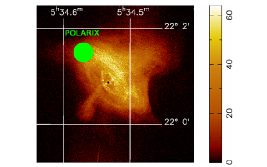
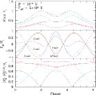
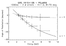
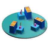
The Crab Nebula is one of the best studied astronomical sources. The first, and the only one so far, polarimetric measurement in the X-rays showed that this source is highly polarized, proving synchrotron as the emission mechanism. The pulsar itself is also highly polarized in the radio to optical bands. Recent INTEGRAL results (Dean et al. 2008Dean2008 , Forot et al. 2008Forot2008 ) showed high level of polarization also in gamma-rays, with the polarization angle aligned to the optical one (and to the rotation axis of the pulsar). The X-ray emission of the nebula is highly structured, as shown by the wonderful Chandra images, with a torus-plus-jet geometry. Detailed and space-resolved measurements by POLARIX (fig.1) will allow us to study the dynamics of the plasma in the nebula and the acceleration mechanism of the pulsar, which is able to convert the large part of its rotational energy in accelerating particles which eventually shine in the nebula by synchrotron emission.
2.1.3 Acceleration Phenomena : QSO
One of the challenges of the present day high energy astrophysics is to understand how matter is accelerated in jets, and how the mechanism responsible for the emission can work both in galactic and extragalactic sources.
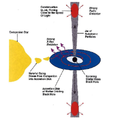
Regarding galactic sources, at present about 2 dozens X-ray binaries show superluminal behavior radio-emitting spots moving away from a compact core apparently (fig.2) faster than the speed of light (Mirabel Rodriguez 1994 Mirabel1994 ). These objects can be extremely luminous in X-rays (1038-39 erg s-1 ; Belloni et al. 1997Belloni1997 ). Their high luminosities and high masses - inferred from optical determination of the orbital parameters (e.g., Orosz Bailyn 1997Orosz1997 ) - indicate that the compact object is a black hole in many of them. Their structure - black hole, accretion disk, and relativistic jet - and their multiwavelength behavior, including gamma-ray emission (e.g., Aharonian et al. 2006Aharonian2006 ) and radio and optical polarization (Nagae et al. 2008Nagae2008 , and references therein) strongly resemble those of radio-loud quasars, of which they seem to be just a scaled down version. For this reason they have been named ”microquasars”. The study of their polarization properties can help shading light on jet formation and its relation to accretion, and the site (disk, corona, or jet) of its origin, which may also be applicable to AGN (e.g. Mirabel 2007Mirabel2007 ), with the additional bonus of allowing us, thanks to the much smaller time scales, to study their behavior over a wide interval of the accretion rate.
These sources are also good candidates to search for General Relativity effects which modify polarization properties, as will be described in the ”Fundamental Physics” section.
2.1.4 Acceleration Phenomena : Blazar and Radiogalaxy
AGN are customarily divided into two subclasses. i.e. radio-loud and radio-quiet AGN, depending on the level of radio emission. In radio-loud AGN, a relativistic, highly collimated jet is present; in the subclass of Blazars, it is directed close to the line-of-sight and all Special Relativity effects are magnified. In particular, due to Doppler boosting, jets dominate the emission at all wavelengths.
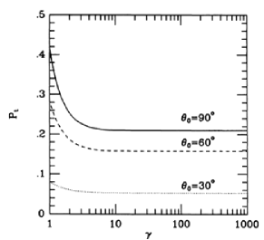
The spectral energy distribution (SED) of Blazars is composed of two peaks, the first one due to synchrotron emission, the second one due to inverse Compton scattering (IC) of either the synchrotron photons (synchrotron self-Compton, SSC) or external photons, presumably from the accretion disk. In some cases, the synchrotron peak dominates in X-rays, and strong polarization is therefore expected. Comparison with the polarization in other bands can elucidate on the structure of the jet. In other sources the IC peak is instead observed in X-rays. In the latter case, X-ray polarimetry will offer a simple way to establish if IC occurs on synchrotron or external photons. While the polarization angles of synchrotron and SSC emission are expected to be the same, and perpendicular to the magnetic field (Celotti Matt 1994Celotti1994 ), in the external photons model the IC polarization is related to the jet axis (Begelman Sikora 1987Begelman1987 ), and the polarization angle in the two peaks needs no longer to be the same. In both models, the polarization degree (fig.3) is expected to be very high, up to 50 or more unless the electrons responsible for the IC emission are hot (see also Poutanen 1994Poutanen1994 ). Multiwavelength polarimetry will therefore provide unique information on the emission mechanism.
In non-Blazar radio-loud AGN, the jet is directed away from the line-of-sight, and the jet emission no longer dominates over the disk-related emission. Interestingly, for a few bright sources (most notably the famous bright quasar 3C 273), Grandi Palumbo (2004Grandi2004 , 2007Grandi2007 ) have suggested that the two components are of comparable importance in the 2-10 keV band. These results are based on a spectral deconvolution, and therefore on assumptions on the spectral shapes of the various components. X-ray polarimetry offers a model-independent way to test this hypothesis: as the two components have different spectra (the jet spectrum being harder), and are polarized with different polarization angles, a rotation of the angle with energy is expected, in accordance with the energy-dependent weights of the two components.
2.1.5 Emission in strong magnetic fields
Ordered magnetic fields cause radiation to be polarized not only because of synchrotron emission (as in the acceleration phenomena discussed above) but also, if strong enough, because they channel the matter along the flux lines, resulting in strong asphericities in the matter distribution. Moreover, plasma opacity in a strong magnetic field is different in the two modes, leading to strong polarization of the emerging radiation.
2.1.6 Emission in strong magnetic fields: Magnetic Cataclysmic Variables
Magnetic cataclysmic variables (mCVs), which include polars and intermediate polars, are binaries with a strongly magnetized white dwarf (WD) accreting material (see fig.4(a)) from a Roche-lobe filling low-mass stars (see Warner 1995Warner1995 for a comprehensive review). The magnetic field is strong enough (1-100 Mgauss) to channel the accretion flow directly to the WD, preventing the formation of an accretion disk in polars and magnetically truncating the disk in intermediate polars (which have a slightly lower magnetic field, but are generally stronger X-rays emitters, because of higher accretion rates). The accreting matter is heated to keV temperatures in a standing shock near the WD surface. The post-shock material is cooled by emitting optical-IR cyclotron radiation and bremsstrahlung in X-rays. The X-rays are in part scattered and reflected by the WD surface, the disk (if present) and the magnetosphere. The polarization characteristics are shown in fig. 4(b)
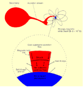
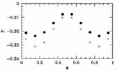
Even if the X-ray emission is mainly due to bremsstrahlung, scattering opacity in the accretion column could not be negligible for high accretion rates, and the emission may be polarized. The polarization depends on the viewing inclination of the system and is sensitive to the system configuration. The viewing orientation of the accretion column varies with the orbital period, and the polarization signals is therefore periodic, with an amplitude reaching 4 - 8 for axisymmetric models (Matt 2004Matt2004 , McNamara et al. 2008 McNamara2008 ). Reflection from the WD surface, which is relevant above a few keV, is also expected to be significantly polarized, providing a characteristic energy dependence of the polarization properties (Matt 2004Matt2004 ). Several bright intermediate polars, and certainly the brightest polar, AM Her, when in high state, can be searched for phase-dependent polarization with POLARIX.
2.1.7 Emission in strong magnetic fields: Accreting millisecond pulsars
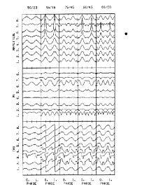
Accretion in close binary systems can spin up the neutron-star rotation, resulting in accretion-powered millisecond pulsars (aMSPs). At present, eight sources are known, with periods ranging from 1.67 to 5.49 ms. Their spectra consist of a blackbody component, likely originating in a hot spot on the neutron star surface and with typical temperatures of about 1 keV, and a hard power-law component, probably due to Comptonization in a radiative shock surface, with a temperature of 30 - 60 keV and optical depths 1-2. The observed pulsations indicate that the shock covers only a small part of the neutron-star surface. The scattered radiation should be linearly polarized (fig.5), with the polarization degree and angle varying with the phase (Viironen Poutanen 2004Viironen2004 ).
2.1.8 Emission in strong magnetic fields: Accreting X-ray pulsars
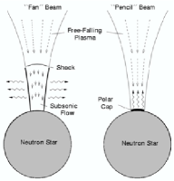
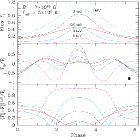
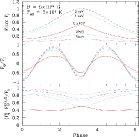
Accreting X-ray pulsars are binary systems (fig. 6(a)) in which the compact object is a Neutron Star, with very strong magnetic fields 1012-1013 G, as derived from the detection of cyclotron lines. In such a strong a field, a birefringence effect, due to the different plasma opacity to the ordinary and extraordinary modes, arises, resulting in a strong linear polarization of the emerging radiation.
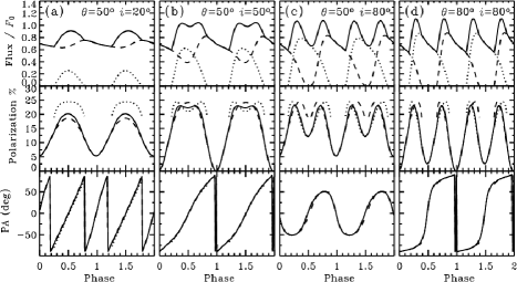
Detailed calculations (e.g. Mzros et al. 1988 Meszaros1988 , fig. 6(b)) show that the linear polarization depends strongly on the geometry of the emission region (accretion column), and varies with energy and pulse phase, reaching very high degrees, up to 70 for favorable orientations. The detailed properties of the X-ray spectrum, pulse profile, and polarization depend on the assumptions made on the physical and geometrical properties of the systems, but nevertheless some general conclusions can be reached. In particular, phase-resolved polarimetry can distinguish between ”pencil” and ”fan” radiation patterns, a long standing problem still awaiting a firm solution. Because the degree of linear polarization is maximum for emission perpendicular to the magnetic field, the flux and degree of polarization are in-phase for fan beams, but out-of-phase for pencil beams. In cases when pulse profiles change dramatically with energy, it is possible that both fan and pencil beam components are present, each component dominating at different energies.
2.1.9 Scattering in aspherical situations:X-ray Binaries
Even when the magnetic field of the compact object is not strong enough to channel the accreting matter, asphericities are present because the matter usually forms accretion disks. GR effects are expected to be important for the emission originated in the inner regions of the disk, close to the black hole or the neutron star. These effects will be discussed in the ”Fundamental Physics” section. Here we just emphasize that in accretion-disc-fed sources the hard component (which is the dominant one in the 2-10 keV spectrum where the sources are in the so called hard state) is likely due to Comptonization of disk photons in a hot corona, and it is therefore expected to be strongly polarized (e.g. Haardt Matt 1993 Haardt1993 , Poutanen and Vilhu 1993 Poutanen1993 ). The polarization degree will put constraints on the, so far unknown, geometry of the corona.
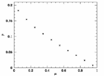
Part of the primary emission is intercepted and reflected by the accretion disk itself, giving rise to the so-called Compton Reflection (CR) component (fig.7(a) . This component, which becomes relevant above 7 keV or so, is also highly polarized , the polarization degree depending mainly on the inclination angle of the disk (fig.7(b), Matt et al. 1989 Matt1989 ).
2.1.10 Scattering in aspherical situations:Radio-quiet AGN
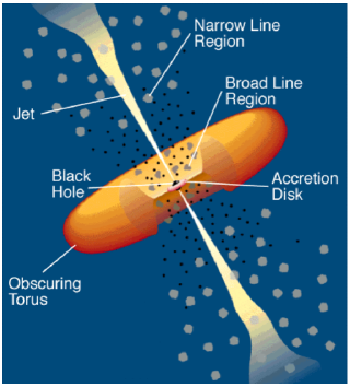
The inner regions of radio-quiet AGN are just scaled-up versions of those present in Galactic Black Hole systems (fig.8), with the very important difference that here the Comptonization component always dominates, as the disk thermal component is in the UV/Soft X-ray band, due to the relation. For the Comptonization and CR components, the same considerations made in the previous paragraph still holds (but see the ”Fundamental Physics” section for a test of GR effects based on time variability).
In addition to the accretion disk, other reflecting regions are present in radio-quiet AGN, first and foremost the so-called torus envisaged in Unification models (Antonucci 1993 Antonucci1993 ). Despite the name, the actual geometrical shape of the ’torus’ is basically unknown, and polarimetric observations can help to solve this issue.
2.1.11 Scattering in aspherical situations:X-ray Reflection Nebulae and the study of the Supermassive Black Hole in the Galaxy
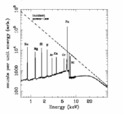
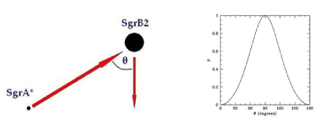
Sgr B2 is a molecular cloud in the Galactic Center region, located at about 100 pc (projected distance) from Sgr A*, the supermassive black hole in the center of the Galaxy. Its X-ray spectrum is well reproduced by a pure Compton Reflection component, indicating that Sgr B2 is reflecting the X-ray radiation produced by a source outside the cloud (Sunayev et al. 1993Sunyaev1993 ). The puzzle here is that there is no X-ray source bright enough in the surroundings. It has therefore been proposed that SgrB2 is reflecting past emission by the central black hole (Koyama et al. 1996Koyama1996 ), which should therefore have undergone a phase of activity about three hundreds years ago. If the emission from the nebula is indeed due to scattering, it should be (Fig.9) very highly polarized (Churazov et al. 2002Churazov2002 ), with a direction of polarization normal to the scattering plane, and therefore to the line connecting Sgr B2 to the illuminating source. Polarimetry will place a strong limit on the position of the source which illuminated Sgr B2 in the past and, if the direction of polarization will point as expected towards Sgr A*, it will be proved that not many years ago the Galaxy was a low luminosity AGN. The precision with which the polarization angle can be measured depends on the polarization degree, but it is of the order of a few degrees, good enough to set very tight constraints on the origin of the illuminating radiation.
It must be noted that the flux from SgrB2 is varying with time (unfortunately decreasing, Koyama et al. 2008Koyama2008 ). However, other reflecting nebulae are present around the central black hole, which are also varying with time (Muno et al. 2007Muno2007 ). The brightest of them when POLARIX will be on orbit will of course be chosen for observation.
2.2 Fundamental Physics
X-ray polarimetry will also have an impact on fundamental physics, allowing for the study of QED effects in extreme magnetic fields, of General Relativity effects in the strong field regime, and even putting constraints on Quantum Gravity theories.
2.2.1 Matter in Extreme Magnetic Fields
As mentioned above, X-ray polarimetry will also allow us to observe a quantum-electrodynamic (QED) effect, i..e the vacuum birefringence induced by a strong magnetic field. Predicted nearly 70 years ago (Heisenberg Euler 1936 Heisemberg1936 ), the effect could not be verified observationally so far. Detailed calculations of this effect in isolated neutron stars (van Adelsberg Lai 2006 Adelsberg2006 ) have shown a strong energy dependence of the polarization pattern for a single source (fig.10(a), fig.10(b),fig.10(c)) and a strong B-dependence when different sources, with different magnetic fields, are compared. Vacuum birefringence has a much smaller impact on spectral parameters, leaving polarimetry as by far the best tool to observe this effect.
2.2.2 Matter in Extreme Gravitational Fields
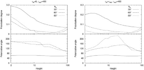
Galactic Black Hole systems. When in a high state, the dominant component in the 2-10 keV emission of Galactic Black Hole binaries is the thermal emission from the accretion disk. The innermost regions of the disk are very close to the black hole, where GR effects are very strong. These effects cause a rotation of the polarization angle of the radiation emitted from the disk, the amount of rotation depending on the azimuthal angle and the radius of the emitting point. Even after averaging over the azimuthal angle, a net rotation remains. The closer the black hole is to the emitting point, the larger the rotation. Because the emission is locally a thermal one, and because the temperature decreases with the disc radius, what is eventually observed is a rotation of the polarization angle with energy (Stark and Connors 1977Stark1977 , Connors et al. 1980Connors1980 , Dovciak et al. 2008 Dovciak2008 , Li et al. 2009 Li2009 Schnittman et al. 2009 Schnittman2009 ) . The effect is particularly strong for a spinning black hole, where the disc can extend down very close to the black hole horizon (fig.11(a), 11(b)). It will be a powerful tool to study the behavior of radiation in the extreme gravitational field of the black holes, and so to test the Gravitational Relativity in the strong field regime. Moreover, it will provide a method to measure the spin of the black hole.
AGN. In AGN, the disk thermal emission is outside the working band of POLARIX. However, GR effects may manifest themselves through time-dependent, rather than energy-dependent, rotation of the polarization angle. In fact, to explain the puzzling time behavior of the iron line in the famous Seyfert 1 MCG-6-30-15 (the best and most studied case so far for a relativistic iron line, Fabian et al. 2000 Fabian2000 and references therein), it has been proposed (Miniutti Fabian 2004Miniutti2004 ) that the primary emission originates in a small region close to the black hole spinning axis, the observed variability being due to the variation of the height of the source (fig.12). If this is indeed the case, the polarization degree and angle of the reflected radiation must also vary in a characteristic way (Dovciak et al. 2004Dovciak2004 ), which depends on the spin of the black hole. Polarimetry can therefore provide a further and powerful probe of radiative transfer in a strong gravity field as well as an estimate of the black hole spin. In MCG-6-3-15, a MDP of about 4 can be reached with POLARIX in 300 ks. A long look (1 MS or more) to this source may provide a first test of the model.
2.2.3 Quantum Gravity
One of the most ambitious efforts of modern physics is to develop a theory that unifies Gravity with the other three forces within a single theoretical framework. Different approaches to Quantum Gravity are pursued (Loop, String, non commutative space-times) all sharing the general problem of finding good observational tests (Amelino-Camelia 2004Amelino2004 ).
One of such few tests can be done with polarimetry. Loop Quantum Gravity predicts that, at the Planck scale, a small birefringence effect is present which, for linearly polarized radiation, results in a rotation of the polarization angle along the photon path (Gambini Pullin, 1999Gambini1999 ). The rotation of the polarization angle is proportional to the distance of the source, and to the square of the energy of the photon, via an adimensional factor of proportionality, . Previous UV and X-ray polarization measurements (the latter performed on the Crab Nebula, the only source for which there is a positive detection so far) have already constrained to be less than about 10-4 (Gleiser Kozameh 2001Gleiser2001 ; Kaaret 2004 Kaaret2004 ) with claims as low as a few times 10-7 based on optical/UV measurements of a Gamma-ray burst afterglow (Fan et al., 2007)Fan2007 . Even tighter constraints to of order 9 10-10 have recently been put by Maccione et al. (2008)Maccione2008 comparing the recent polarization measurement of the Crab pulsar in soft gamma-rays with INTEGRAL with the optical observations (6 10-9 if only the gamma-ray result is used.)
A deeper test of the theory would require, on the one hand, measuring (or putting upper limit to) values of as small as possible; on the other hand, to check results against e.g. possible errors due to intrinsic polarization angle variability by looking to different sources at different distances. Several bright enough Blazars at different distances are available to put the result on a firm statistical basis.
3 POLARIX design
3.1 Mission Description and Design Drivers
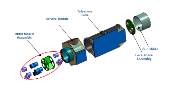
POLARIX is composed of four basic elements: (1) the Service Module (2) three (possibly five) telescopes with 3.5 m focal length, (3) the Mirror Modules which accomodates the telescopes, inserted into the Service Module, (4) the Focal Plane Array composed by a structure containing the Gas Pixel Detectors (GPD). POLARIX will be able to detect in 10 a polarization higher than 10 for a 1 mCrab source, with an energy resolution of 20 at 6 keV, an angular resolution of about 20 arcsec and a field of view of 15 arcmin x 15 arcmin. In the following paragraphs we will describe in detail the components of POLARIX.
3.2 Philosophy
POLARIX capabilities are determined by the performances of the telescopes combined with the GPD. Both the telescopes and the GPD are already existing and qualified.
The general philosophy driving the design of POLARIX is to have a mission fully exploiting these capabilities, while remaining within the (ambitious) budget limitations fixed by the Italian Space Agency (ASI) Announcement of Opportunity (AO) for Small Missions. We coped with this tight economic constraint thanks to :
-
•
a satellite platform as standard as possible
-
•
commonalities with other missions
-
•
a plug and play philosophy of Assembly Integration and Verification (AIV) (to simplify Payload/ Service Module integration).
-
•
a Ground Segment organization assigning a major role to science institutes.
-
•
a minimal mission duration
-
•
a prime contractor role assigned to a scientific institution (INAF).
3.3 Optics
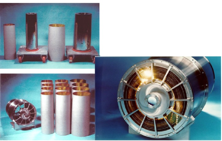
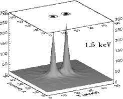
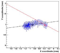
As part of the JET-X project, four mirror modules were built, 3 flight units (FM) and an Engineering Qualification Model (EQM). The EQM has been used for the qualification test campaign, but it has the same characteristics of the 3 FM units. One of these units is shown in fig. (13) below. These mirror modules were developed at the Brera Observatory and were manufactured by Medialario. They have 12 concentric gold-coated electroformed Ni shells with a focal length of 3.5 m. The shells are 600 mm long with diameters ranging from 191 to 300 mm. The effective area and point spread function of these mirrors have been measured at the Panter facility for a range of energies and off-axis angles. The last calibration campaigns were performed on the third flight model, FM3, that is now onboard the Swift satellite. As a standalone unit they were measured the last time at the Panter facility in July 2000. A calibration image of two sources displaced by 20 arcseconds (Fig.14) immediately shows the image quality of these mirrors and their capability to separate two nearby sources. The total effective area of a single unit is 159 at 1.5 keV and 70 at 8 keV, while the Half Energy Width (HEW) is 15 arcsec at 1.5 keV and 19 arcsec at 8 keV (Citterio et al. 1996 Citterio1996 ). For the most recent results on the inflight calibrations of the mirror unit now flying onboard Swift see Moretti et al. (Moretti2005 ) and Romano et al. (Romano2005 ). The total mass of each unit is of 59.9 0.5 kg. The maximum diameter of one Mirror unit occurs at the interface flange and it corresponds to a diameter of 388 4 mm. The maximum height is 667.5 5.0 mm. The interface mounting of each unit has a planarity of 0.02 mm and a circular shape ring of 20 mm diameter. Each unit consists of a forged stainless steel cylinder, fitted at each end with a stainless steel shell support or spider. The mounting interface flange is at the center section of the cylinder. The twelve electro-formed nickel mirror shells are mounted concentrically within the mirror cylinder, controlled by grooves machined into the spider units. The mirror alignment reference flat is carried at the center of the forward spider. Both spiders also carry the required beam stops and blanking plates. The thermal environment for the Mirror units must be such that the HEW would not be degraded by more than 10 arcsec. This implies that the mirror units should have a thermal gradient of less than 2∘C.
3.4 Focal Plane
The Focal Plane (FP) structures are composed of a detector mounting plane and a sunshield; the interface with the lightshield tube (described below) is provided by a continuous Al ring. The lightshield tube encircles all the detectors and connects the FP to the service module and to the optics module. The harness (power, data) will run from the Focal Plane to the Service Modulus through the lightshield tube.
The Focal Plane contains three Front Ends and the associated Back End electronics (BEE, Fig.15(a)). Each Front End unit contains the detector, a filter wheel with calibration sources (see next paragraphs) and a baffle with an electrostatic grid on top.
The BE electronics units, one for each detector unit, are close ( 20 cm) to the detectors, (fig.15(b)). The High Voltage Power Supply (HVPS) are inside the BEE boxes to reduce the noise.
Each detector is inserted in a dedicated box which will be thermally controlled by a Peltier at a mean temperature in the 10∘-20∘C range with a max oscillation of 1∘C. The weight of the focal plane (excluding the harness) is shown in table 1.
| Unit name | Quantity | Mass (kg) | Total (kg) |
|---|---|---|---|
| Detector | 3 | 0.4 | |
| FW,baffle, box | 3 | 2.85 | |
| Front-end total | 3 | 3.25 | |
| Back-end electronics | 3 | 3.5 | |
| Focal plane tray | 1 | 4.5 | |
| Focal plane sun-shield | 1 | 9 | |
| Total | 33.55 |
3.4.1 Detectors
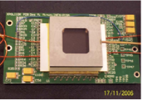
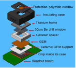
The purpose of each focal plane instrument is to provide, in the energy range 2-10 keV, polarization measurements simultaneously with angular, spectral and timing (at few s level) measurements. Each instrument is based on a Gas Pixel DetectorBellazzini2006 Bellazzini2007 , a position-sensitive counter with proportional multiplication and a finely subdivision of the charge collecting electrode in such a way that photoelectron tracks can be accurately reconstructed, as shown in fig. 16.
The Gas Pixel Detector is an advanced evolution of the MicroPattern Gas Chamber. It is based on a gas cell with a thin entrance window, a drift gap, a charge amplification stage and a multi-anode readout which is the pixellated top metal layer of a CMOS ASIC analog chip (105600 pixels at 50 m pitch). The sealed GPD is shown in fig.17(a). The different components are shown in fig.17(b). When the X-ray photon is absorbed in the gas gap the ejected photoelectron produces an ionization pattern in the gas (track). The track is drifted by a uniform electric field to the Gas Electron Multiplier (GEM) where the charge is amplified. The linear polarization is determined from the angular distribution of the photoelectrons as derived from the analysis of the tracks. The analysis algorithm reconstruct the impact point with a precision of 150 m FWHM, largely oversampling the PSF. The FOV is 15 15 square arc minutes. The effect which mostly affects the resolving power is the blurring due to the transversal diffusion in the gas of the ionization track along the drift path to the collecting electrode.
Below the GEM, at a distance less than a few hundred micron, the top layer of the multilayer ASIC is covered with metal pads with a high filling factor distributed on a hexagonal pattern. Each pad is connected underneath to its own independent analog electronic channel. The average noise of the electronics is only 50 rms. With a moderate gain of 500, single electrons produced in the gas cell can be detected. The system has self-triggering capability and only the charge of the pads included in a window around the pixels which have been triggered are read-out and digitally converted. In this way data volume and read-out time are significantly reduced, and only sub-frames of 400 to 600 pixels (the so called Region of Interest, ROI), which include the track completely, are extracted in real time at each event.
From the point of view of construction, the GPD is a conventional proportional counter coupled to a VLSI chip. From the existing data on ageing tests made with mixtures based on noble gases and various quenching, including Dimethyl Ether (DME), the GPD gas mixtures can withstand the radiation levels for POLARIX. The major problem can be the long term pollution of the mixture itself. However, since a long experience exists on sealed gas counters operating in space for years, there is strong confidence that, with the procurement of very pure gas and a proper selection of materials to be used inside the detector, the problem can be overcome. Long term stability in a sealed gas cell with Beryllium window was achieved not only for proportional counters (e.g. COS-B, HEAO-1, Einstein, GINGA, XTE) but also for Gas Scintillation Proportional Counters (GSPC, TENMA, ASCA, SAX) which are extremely sensitive to pollution from out-gassing. Presently, a sealed detector is working for more than two years without showing any degradation of the performances. All the construction procedures are compatible for use in space. The GEM is a metal-coated Kapton film, similar to that used in the Stellar X-ray Polarimeter (SXRP) detectors. The detector is a sealed body with no gas refilling system. It is self-standing with a total weight of a few hundred grams, mainly due to the HV distribution, potting and connectors. The gas volume (10 mm absorption/drift gap), as the baseline, is filled with 20He-80DME at 1 bar. Based on studies in progress, the pressure could be increased to 2 bar to improve the efficiency especially at higher energies. The mixture could also be substituted with other mixtures, less sensitive to lateral diffusion during drift, to allow for thicker absorption/drift gap. In this case the overall length could increase by 10 mm. The baseline window is 50 m of Beryllium. If technology will show that an improved performance can be achieved at energies below 1.5 keV, a thin plastic window could be adopted. The read-out VLSI ASIC chip, based on 0.18 m CMOS technology, has been already successfully tested. The self-trigger download mode works perfectly. All the major functions have been already tested and are compliant with the requirements for the GPD.
3.4.2 Radiation hardness
A major problem found in past X-ray missions with gas detectors with multiplication was the effect of highly charged particles on the electrodes. The passage of heavy nuclei in the multiplication regions may give rise to self-sustained sparks that can damage or even destroy the electrodes. This was a serious problem for, e.g., XTE/ASM or INTEGRAL/JEM-X, resulting in a reduced performance of the detectors; in EXOSAT/PSDs it was the likely cause of the failure of both gas detectors. This problem is usually prevented by introducing limitations to the current that can flow in the stage. In any case, the criticality is there whenever the detector is operated to a gain level too close to the break-down level. Thanks to the low noise and to the fully pixel concept we operate the GEM at a very low gain, orders of magnitude from the break-down value. In any case, we extensively tested a GPD with X-ray fluxes comparable to three years of operation in space. The most significant test was performed at Heavy Ion Medical Accelerator in Chiba in Japan. The GPD was irradiated with Protons (E 160 MeV), He, C, N,O, Ne, Si, Ar, Fe and Xe. Tests with Fe were particular significant. GPD survived to a dose of Fe ions of 500 MeV/n, equivalent to that expected in 40 years of operation in a low Earth orbit.
3.4.3 Back-End electronics
The ASIC output consists of the information about ROI coordinates and the charge collected by each pixel within the ROI. Coordinates are expressed by four binary words (xmax[8..0], xmin[8..0], ymax[8..0], ymin[8..0]), while charge is given as Front End analog output. At the trigger a ROI is internally indexed and the control electronics can begin to read it out. The charge of each pixel is serialized on a common analog output. A differential output buffer is used to drive this signal to the ADC.
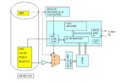
The block diagram of the BEE is shown in fig.18. The analog output from ASIC will be A/D converted at the interface BEE. The ASIC will be controlled by a dedicated FPGA, the A/D converted data will be zero-suppressed, a microprocessor will manage the telecommand and the housekeeping (HK). The interface BEE will also assign the time to each event. The BEE is the assembly that contains the electronic boards placed between the detector assembly (Front-End Electronics (FEE) = GEM + Readout ASIC) and the Control Electronics box (CE).
It is responsible for :
-
•
Distributing and filtering the power supply required to the low voltage front-end electronics;
-
•
Supplying the detector with all the high voltages needed;
-
•
Managing the Front-End Electronics;
-
•
Implementing a spectroscopy electronic chain for the GEM analog output;
-
•
Digitally converting the analog output of the FEE (ADC function);
-
•
Storing auxiliary information related to each event (e.g. X,Y coordinates of the ROI corner);
-
•
Time-tagging the events with 8 s of resolution and 2 s of accuracy with respect to the Universal Time (UT) (from GPS);
-
•
Digitally performing some basic processing (pedestal calculation, suppression of not-fired pixels)
-
•
Temporarily storing the converted data (both from ASIC and GEM);
-
•
Integrating some HK and Science Ratemeters related to the detectors activity (e.g. good event, rejected events, …);
-
•
Providing Instrument HK to the CE for active monitoring and telemetry purposes.
-
•
Implementing the Peltier Driver for the detector temperature control.
For analog signal integrity reasons, this back end assembly is placed close to the detector assembly.
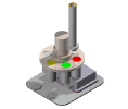
3.4.4 Calibration sources
The detectors will be accurately calibrated on ground. Although available data show a good stability with time, we want to preserve the capability to calibrate periodically during the flight in order to check the long term stability for possible change of the components and/or for the possible aging of the GEM or of the filling mixture. We want to calibrate the efficiency, the gain, the energy resolution and the modulation factor for a minimum of two values of the energy. The calibration will be done with both unpolarized source and polarized source (Muleri 2007, Muleri2007 ). Calibration sources will be mounted in three positions of the filter wheel.
In the following we describe both types of calibration sources.
-
•
Polarized calibration source.
The modulation factor of the polarimeter increases with energy because the tracks become longer and straighter, since the specific energy loss and the effect of Rutherford scattering decrease. A simultaneous measurement at two energies is highly desirable to monitor the behavior of the polarimeter in space. Bragg diffraction of X-ray lines or continuum tuned at nearly provides nearly polarized radiation. To generate X-rays in space, instead of an X-ray tube, we can use a fluorescence source of adequate intensity such as . Its Mn K-lines can excite 2.6 keV line from a thin PVC film. Graphite crystals at can reflect those 2.6-keV lines polarizing them nearly at 100. LiF crystal reflects the K-alpha line photons close to 47.6 degree polarizing them at 88 . We want to exploit both lines with a composite X-ray calibration source. A thin (20 m) Graphite crystal is attached to a LiF thick crystal to polarize simultaneously 2.6 keV and 5.9 keV photons. A sheet of 40 m thick PVC crystal is placed in front of the source to convert part of the X-ray photons into 2.6 keV Chlorine photons. The unabsorbed X-ray photons will cross the graphite crystal to be reflected by the LiF. The source will be compact (small volume and weight) to allow for a safe use in space. The monitoring of the modulation factor during the observation will also allow us to check whether any pollution has altered the drift (and therefore the diffusion coefficient) in the gas mixture.
-
•
Unpolarized calibration source.
The gas gain of the detector is a function of the voltage difference across the GEM. Pollution of the gas due to outgassing and ageing of the gas mixture can require higher voltage difference to reach the same gas gain. We want to monitor the gas gain using two radioactive sources. One radioactive source will be Fe55 . The Fe55 photons impinge into the whole detector surface to monitor the gain across it. The counting rate will be 20 c/s. can be a point source or a source diffused in a circular surface. The second X-ray sources will be Copper (8.04 keV) photons extracted by a radioactive Cd109 source. This second X-ray source will be used to monitor the linearity of the gas gain with time. The counting rate of this second source will be 10 c/s.
3.5 Control Electronics
The Control Electronics (CE) is a data handling unit dedicated to the on-board data processing and the power Scientific Instrument control. The CE constitutes the central node of the Payload, managing the data and the power interfaces towards the scientific detectors and the spacecraft. The unit high level architecture is shown in fig.19.
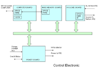
The CE is aimed at performing the following principal tasks:
(1) parse and execute the TCs coming from the S/C; (2) generate scientific and HK telemetries; (3) generate messages, warnings and errors reports; (4) manage the Payload Instrument Operative Modes (Boot, Maintenance, Idle, Observation and Test); (5) implement the detector thermal control algorithms; (6) control the positioning of three Filter Wheels; (7) A to D convert all the Payload analog HK lines both for thermal control, position control and HK purposes; (8) perform the Instrument Control Function, i.e. the active monitoring of some Payload safety critical parameters in order to implement a nearly real-time reaction to avoid damages; (9) in the case of high science data rates, store this data into a Payload Mass Memory (implemented inside the CE); (10) perform science data processing.
3.5.1 Scientific Data Acquisition
The observation program foresees both faint and bright sources, with the constraint due to the available average telemetry bandwidth (50kbit/s).
For the purpose of sustaining high data rates of bright sources, two strategies are available with the proposed CE architecture: (1) temporary data storage on a Payload Mass Memory; (2) on board track reconstruction to transmit on ground only the main photon parameters.
The Payload Mass Memory will be used only when necessary in order to bufferize scientific data that exceeds the available telemetry bandwidth.
The difference between the two strategies is that the mass memory can only differ the delivery time of the generated data, whilst the on board track reconstruction is able to reduce the transferred data for each photon: the only disadvantage is the loss of some information (raw data are more complete than photon parameters only).
3.5.2 Scientific Data Processing
The on-board track reconstruction is thought to dramatically reduce the science telemetry volume. In fact in this case, instead of sending to ground TM packets in which the photon information is represented by all the pixels in the track (address and charge; the average number of pixel per photon is 50), only the photon polarization characteristic (photon impact coordinates, energy, emission angle and a few quality parameters allowing for off-line further selection of events) is transmitted. It can be estimated that in case of on-board track reconstruction, the average science TM flow will be reduced by a factor 8. As explained in the next paragraph, the on-board track reconstruction implies the use of a DSP. However the baseline for the CE foresees a TSC21020 DSP for two main reasons: (1) it involves a consolidated architecture (for example it was successfully used on AGILE CE, MARSIS and SHARAD programs)(2) this architecture is powerful and has a minimum impact on the hardware if the on-board processing option is chosen.
The mathematical algorithm at issue implies the estimate of the first, second and third moment of the track by executing a series of calculation loops involving floating point operations.
The computational load determined by the execution of the track reconstruction algorithm has been evaluated for the TSC21020. The result of the analysis proved that the selected DSP is capable of sustaining the event peak rate for the POLARIX mission determining a CPU occupation lower than 30%.
3.6 Payload main budgets
Table 2 summarizes the results of the telemetry data rate estimate with special focus on the Mass Memory occupation. In table 3 the POLARIX payload power budget and mass budget are shown.
| with zero-suppr. | with on-board analysis | note | |
| Average time rate | 35 kbit/s | 4.25 kbit/s | 30 ev/s |
| Peak time rate | 231 kbit/s | 28.1 kbit/s | 200 ev/s |
| Mass memory usage after 1day @ ptr | 100 | 12.2 |
| Unit name | Quantity | Primary power (W) | Total Primary Power (W) | Mass (kg) | Total Mass (kg) |
|---|---|---|---|---|---|
| Back-End electronics | 3 | 12.9 | 38.7 | 3.5 | 10.5 |
| CE | 1 | 15.3, | 15.3 | 4 | 4 |
| PPS Generator | 1 | 10 | 10 | 5 | 5 |
| TOTAL | -, | 64.1 | - | 19.5 |
4 Mission analysis
4.1 Orbit
The orbit selected for POLARIX is an equatorial circular LEO (Low Earth Orbit), achievable by Vega Launcher (the ESA smallest launcher). The specific orbital features are the following:
-
•
Altitude 505 15 km
-
•
Inclination 5∘ 0.15∘
-
•
Sun eclipse duration 36 minutes max
This specific orbit allows the utilization of ASI Ground Station at Malindi (Kenya). The POLARIX visibility from the Malindi Ground station is 8 - 11 min per orbit.
The nominal mission duration is 1 year, plus 3 months for commissioning and 1 month for decommissioning. For nominal operation the satellite can be supported by the Malindi ground station only. The launch has been considered in 2014 , when solar activity decreases.
The selected orbit features and the estimated delta V reduction from atmosphere drag (mission life-time during solar minimum phase) can be maintained without any orbital correction. Consequently the satellite does not strictly need a propulsion sub-system.
4.2 Launcher
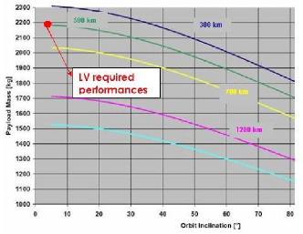
The launch site is Kourou, latitude 5.0647∘ and longitude 307.3602∘. The typical Vega mission includes a three stage sub-orbital ascent (Vega User Manual, Issue 3/ Revision 0, March 2006).
| Parameter | 1 accuracy |
|---|---|
| Altitude | 15 km |
| Inclination | 0.15∘ |
| Launch time | 3 sec |
The Vega Launch Vehicle can be launched any day of the year and any time of the day. Performance data for circular orbit missions with different inclination and altitudes are presented in fig.20. Also table 4 provides the injection accuracy.
4.3 Ground contact and data retrieval
Ground Contact
The Malindi ground station is optimally located for the near equatorial POLARIX Satellite orbit. The coverage pattern for this LEO altitude is a regular sequence of contacts, it is planned to have 15 contacts a day with an average duration of 8 minutes each and an average contact period of 120.5 minutes a day. Assuming this contact time and telemetry high data rate as 512 kbps (with Reed-Solomon coding), the data volume downloadable is 3.25 Gb/day.
5 Spacecraft description
5.1 Satellite design overview
Thanks to an intensive interaction between the institutes and the industries a POLARIX mission scenario, compatible with the Small Mission ASI conditions, has been identified. The severe cost limits imposes a ”design-to-cost” approach. This approach is feasible due to the very good level of commonalities with other projects (Cosmo-SkyMed, Radarsat, Sentinel and GOCE). Moreover this approach implies the utilization of standard technology and the selection of the lowest cost option for the system equipments.
In synthesis the POLARIX satellite is composed of the following main elements:
- the Service Module, which provides all the necessary functions for the performance of the scientific payload (on-board computer, thermal control, power generation etc.).
- the 3.5 m Telescope Structure, which realizes the distance between the Focal Plane Array and the Mirrors Modules along their main axis and support a Solar Array panel (component of Service Module)
- the Mirror Modules Assembly, accommodate a mechanical structure inside the cylindrical thrust of Service Module. Each mirror module is equipped with baffle (for thermal control) and a thin thermal (for thermal and contamination control).
- the Focal Plane Array, composed by a structure accommodating the 3 detectors, the Electronics Interface Unit containing the functions specific to the detector module and a Sun shield. Also the payload data handling unit is a component of Focal Plane Array but, in order to optimize the mass distribution, it is host in the Service Module.
The Mirror Modules telescopes and the Focal Plane Array make up the POLARIX scientific payload.
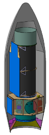
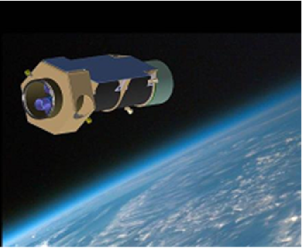
Strong hardware modularity for main elements is considered with noteworthy advantages on the development schedule. In particular the payload can be developed in parallel with the other satellite elements. Final system satellite integration considers a direct, ’plug-and play’ of the main elements. Fig. 21 shows the POLARIX launch configuration inside the Vega firing. Fig.22 is an exploded view of POLARIX, where satellite main elements are identified while fig.23 is a pictorial view of POLARIX Satellite.
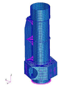
5.2 Mechanical and thermal design analysis
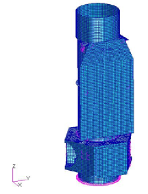
Preliminary Mechanical and thermal analysis has been performed to support the satellite system design. Figures 24(a) and 24(b) show the Finite Element Model (FEM). On the basis of FEM the mechanical structure has been designed and the satellite structure mass consolidated. The mechanical environment simulated by the satellite’s FEM is compatible with the mechanical design references of Mirror and Detector modules.
Preliminary thermal control design has been supported by a dedicated satellite Thermal Mathematical Model (TMM). The thermal control items (heaters, thermal blanket, Sun shield) have been consolidated thanks to various environmental thermal condition simulated with the TMM.
For the Payload thermal control design the reference payload temperature are: - Mirror Module : 20 oC 2 oC - Detector Module : 15 oC 2 oC.
The preliminary thermal analysis has demonstrated the feasibility of payload thermal control by means of a standard approach. Moreover the max heater power request estimated by the preliminary thermal model is the following (three telescope configuration case) :
- Mirror Assembly : 45 W - Detector Array : 73 W - Service module : 50 W
5.3 The Satellite pointing and attitude control
POLARIX satellite is a 3-axes attitude controlled platform able to perform the fine pointing and the slew manouvre requested by the scientific mission. The recognized design drivers for POLARIX pointing required to meet the scientific mission goal are shown in table 5. Attitude Measurement Error (AME) and Absolute Pointing Error (APE) have been considered for each axis normal to the spacecraft Line of Sight (LOS). AME and APE are considered at 95 confidence level (2 sigma with normal distribution error) on the set of all the possible scientific observations (spacecraft pointing).
For satellite re-pointing (up to two times each orbit) the angular acceleration to be considered is greater than with an angular rate up to .
During the POLARIX phase A study, a preliminary design of Attitude Control Subsystem has been developed, demonstrating that by a proper selection of on-the-shelf sensors/actuators, the pointing and attitude control of the satellite can be met by a proper selection of standard/off-the-shelf equipment.
For POLARIX pointing and attitude determination and control it is relevant to highlight the identification of two engineering solutions, with advantages in terms of cost and mission reliability, i.e.: - attitude determination approach full gyroless by means of 2 or 3 optical heads; - the adaptations and/or minor customizations of Attitude and Control software developed in others projects.
| Description | Mandatory Requirement or constraint | nice to have |
|---|---|---|
| Absolute measurement accuracy | 10” 5 Hz | 10” 10 Hz |
| Absolute pointing error | 5’ | 3’ |
| Total number of pointing | 150yr | 2orbit |
| Sky accessible | 90∘20∘ | 90∘30∘ |
| forbidden direction | none | none |
5.4 Mass and power budget
| Item | weight |
|---|---|
| Total Service Module Mass (kg) | 389 |
| Total Payload Module Mass (kg) | 335 |
| System level margin (20) | 145 |
| Launcher adapter | 45 |
| Total Mass at launch (kg) | 913 |
The total mass of 913 Kg allows a very large margin for launch with Vega (capability of 2300 kg for injection at the selected orbit).
| S/S | LEOP | Sunlit Contact (W) | Eclipse Contact (W) | Sunlit NoCont | Eclipse NoCont | Remarks |
|---|---|---|---|---|---|---|
| DHS | 32.4 | 32.4 | 32.4 | 32.4 | 32.4 | |
| AOCS | 14.0 | 169.2 | 169.2 | 169.2 | 169.2 | |
| PWR | 44.0 | 644.0 | 44.0 | 644.0 | 44.0 | |
| TTC | 16.8 | 32.4 | 32.4 | 16.8 | 16.8 | |
| PL | 0.0 | 56.4 | 56.4 | 56.4 | 56.4 | |
| TCS | 0.0 | 120.0 | 120.0 | 120.0 | 120.0 | |
| SS Total | 107.2 | 1054.4 | 454.4 | 1038.8 | 438.8 | Sun Ecl |
| Harness Losses | 3.2 | 13.6 | 13.6 | 13.2 | 13.2 | 3 |
| PCDU losses | 6.4 | 63.3 | 9.1 | 62.3 | 8.8 | 6 2 |
| System Margin | 21.4 | 66.9 | 66.9 | 63.8 | 63.8 20 | |
| Total | 138.3 | 1198.2 | 544.0 | 1178.1 | 524.5 |
6 Ground Segment and User Segment
The POLARIX mission is expected to operate in a low-Earth equatorial orbit, using the ASI Ground Station in Malindi (Kenya) as a primary ground station. The onboard telemetry production rate is limited to 50 kbit/s. The satellite mass memory will be fully downloaded once per orbit, when the satellite passes over Malindi. The total 300 Mbit of each data download will be transmitted, through the ASINET link, to the Telespazio facility in Fucino. The ground support of the POLARIX mission will consist of two main elements: the Ground Segment (G/S) and the User Segment (U/S). The Ground Segment will perform two main tasks: operate the POLARIX satellite during all the phases of the mission in nominal and contingency conditions; serve the scientific observation requests during the operational phase of the mission. The POLARIX G/S performs the main functions/operations needed at ground level to manage the mission both in terms of satellite control and global data management. The planned G/S includes the ground station of the Italian Space Agency (ASI) located at Malindi and the Mission Operation Center (MOC) located at the Telespazio Fucino Space Center. The G/S provides all the functions to: (a) monitor and control the satellite platform and payload; (b) perform the orbit/attitude operations and generation of orbit products used within the G/S for satellite MC, payload management, mission planning and product generation; (c) generate the mission planning and checks, according to scientific observation requests coming from the U/S; (d) acquire the raw satellite data (housekeeping and telemetry) and transfer them to the U/S for processing. The G/S includes also the Satellite Simulator and the Communication Network responsible to interconnect the Ground Segment facilities and to provide the related communication services in a secure and reliable way.
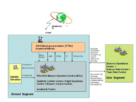
The U/S manages the scientific observation requests coming from the scientific community, forwards them to the G/S for payload scheduling activities, ingests the raw satellite data coming from the G/S, generates, archives, catalogues and delivers the scientific data and the data products to the user community. Communication between the Fucino Mission Operations Centre and the Malindi ground station will be allowed through the ASINET infrastructure provided by ASI. A further connection between the MOC and the scientific community will be possible by means an ISDN line which will ensure the communication between the ASINET node in Fucino and the User Segment located in Frascati.
6.1 Data policy
POLARIX is a PI mission but since its scientific exploitation is open to the worldwide community, it will be conducted through a standard observatory management. The scientific objectives of the POLARIX mission are expected to be achieved by pointed observations typically lasting from one day to one week. The POLARIX scientific program will be then composed of a sequence of staring observations. A Core Program for the mission is planned in the first year, covering 25 of the available net observing time, ensuring that the main scientific goals of the mission are achieved. The POLARIX Team will have the responsibility for the scientific exploitation of the Core Program data. The remaining 75 of the observing time is planned to be accessible to the world wide community on a competitive basis through an Announcement of Opportunity to be issued before the launch. Both Core Program and Guest Observer Program (GOP) can include Target of Opportunity observations. After ascertaining the feasibility of the observation, the proposals will be selected on the basis of their scientific quality, as assessed at a peer review by a Time Allocation Committee. A proprietary period of one year of data is guaranteed, starting with the delivery of the data and the relevant analysis software and calibration files. After one year the data will be put in an open access archive. Guests will be supplied with a Guest Observer Handbook to prepare proposals and analyse data, with documented software tools, based on open source codes and with all data needed for a full exploitation. The distributed data will be based on lists of qualified events including absorption point and time, energy and polarization angle, plus the data on coverage, time windows and dead time. All the data, including those of the GOP, will undergo a Standard Scientific Analysis (SSA), aimed only at guaranteeing a high scientific quality of the data, before their delivery to the observer together with the results and products of the SSA. The analysis of the tracks, the analysis of calibrations and the production of the response matrices of the instrument are the responsibility of the POLARIX Team.
6.2 Data Analysis
The software required to reduce and analyze the POLARIX data will be developed by the POLARIX Team, who will take the responsibility for distributing it to the Guest Observers, to document and to maintain it. The POLARIX software will be based on license-free programming languages. The POLARIX Scientific software will enable the following analysis. The data reduction will start with the pre-processing, that is the conversion of telemetry files into separated FITS files, depending on the information they contain. Output data from the pre-processing will be provided to the scientific and quick look analysis. These packages will run automatically after every satellite contact with the Malindi ground station. A SSA is planned to be carried out on all data as early as possible after the completion of a continuous observation of a given target, regardless of the data rights, with the aim of verifying and guaranteeing the scientific quality of the data. The results of the SSA will pass through a pre-defined set of quality checks, as automated as possible. After successful verification, the results of the SSA will be archived and made available to the owner of the data rights through a password-secured Web page for scientific exploitation, and to the POLARIX Team for Quick Look Analysis and calibration purposes only. After the period of proprietary data rights has expired, the SSA will be made publicly accessible through the POLARIX Public Data Archive. A Quick-Look Analysis (QLA) of the POLARIX data will be carried out under the responsibility of the POLARIX Team on different time scales: orbital, daily-incremental, and complete observation. The aim of the QLA is to discover unusual and noticeable astrophysical phenomena that are of interest to the scientific community and require a prompt information distribution in order to carry out related and/or follow-up observations. The software package for carrying out the QLA will be developed and maintained by the POLARIX Team. The processing-log and the results of the QLA will be archived in a database. After passing all the standard data processing (pre-processing, data reduction, standard analysis, QLA) the POLARIX data will be delivered to the data rights owner for that specific observation. He/she will receive the complete set of reduced data (photon list and auxiliary data) needed for an optimal scientific exploitation, together with the results of the SSA. In order to carry out specific, non-standard analysis, or to verify the results of the SSA, the POLARIX Team will distribute to the GO a documented software package, that the GO will use under her/his own scientific responsibility, the POLARIX Off-line Scientific Analysis Software (POSAS). The POSAS will be developed, maintained and documented under the responsibility of the POLARIX Team, and new releases will be distributed periodically, together with the relevant calibration files. The POSAS software will be based on the FTOOLS software.
6.3 Data Storage
All the data and products at their different steps (Telemetry, Level 1, Photon List, Products) will be stored and archived for future access and use. All the archives will be accessible by means of user-friendly web interfaces and will be open to the individual GOs as their proprietary data, and to the general user as the public data. Similarly, the calibration and the scientific software needed for analyzing the accessible data will be archived and made accessible by an open web interface. The data and the CALDB will be written and stored in the OGIP-FITS standard format and structure.
7 POLARIX performances
7.1 Characteristics of the polarimeter
The characteristics of the polarimeter are shown in table 8
| Characteristic | Value |
|---|---|
| window thickness | 50 m |
| pixel-size | 50m |
| number of pixels | 105600 |
| area of the GPD | 1.5 cm 1.5 cm |
| Focal Length | 3.5 m |
| no. of telescopes | 3 |
| Field of View | 15’ 15’ |
| Baseline mixture | He-DME (20-80) |
| Dead time | 50 s |
| Time resolution | 8 s |
| Time accuracy | 2 s |
| Energy band | 2-10 keV |
| Energy resolution | 20 @ 5.89 keV |
| Crab total counting rate | 145.6 cnts/s/cm |
| Crab MDP (105s) | 0.396 |
| Sensitivity | 12 @ 1 mCrab in 105s |
7.2 Polarimetric performances
In the Gas Pixel Detector, filled with the proper mixture of gas, the tracks produced by a photoelectron in the gas can be visualized. From the analysis of the tracks, the impact point of the photon and the angular direction of the photoelectron are derived.
7.2.1 Capability to measure the polarization of a cosmic source
.
In practice, this means to find a modulation of the histogram of the emission angles,, (the so-called modulation curve), which exceeds that produced by random fluctuations at a predefined level of probability. This is usually expressed as the Minimum Detectable Polarization (MDP).
| (1) |
where is the modulation factor, a number within 0 and 1, that corresponds to the amount of modulation induced by 100 polarized source. If the modulation curve of a 100 polarized source is fitted with:
| (2) |
then the modulation factor is :
| (3) |
B is the background count rate (residual background and diffused X-ray background), T is the net observing time in seconds while S is the source count rate which depends on the quantum efficiency of the detector ( which in turn depends on the gas mixture, the gas thickness and the window transmission), on the telescope effective area and on the spectrum of the X-ray source.
The MDP should not be confused with the measurement error (Weisskopf et al., 2009, 2010 Weisskopf2009 ,Weisskopf2010 ). The level of background in an imaging device at the focus of a telescope is in any realistic case negligible with respect to the counts from the source. This means that the polarimetric sensitivity is limited by the fluctuations of the unpolarized fraction of the source itself and the equation reduces to:
| (4) |
for a 99 confidence level. The sensitivity to the polarization angle is also connected to this parameter so that the MDP is the synthetic parameter describing the performance. The MDP depends linearly on the modulation factor and on the square root of the product of the collecting area of the telescope and the conversion efficiency of the gas. The baseline mixture, He (20) plus DME (80), is already compliant with the scientific requirements, but the search for other mixtures or fine tuning of the thickness of the absorption gap and/or of the filling gas pressure, to further improve the polarimetric sensitivity, will continue during the development phases, since this will not impact on the design and development of the other subsystems. The practical parameter to compare the performances of different polarimeters at the focus of the same telescope is the quality factor (QF):
| (5) |


The modulation factor (), the efficiency () and the quality factor are shown in fig. 26(a) and in fig. 26(b). The modulation factor increases with energy since the emission angle determination is more accurate for longer tracks, while the efficiency drops at low energies because of the window transmission (50 m of Beryllium) and at high energies due to the decreasing opacity of the gas mixture.
The Minimum detectable polarization for the POLARIX mission is shown in fig.27
7.2.2 Capability to control systematic effects
Control of systematic effects has been and still is a dramatic limitation for polarimeters based on Compton scattering. On the other hand, the complete visualization of the track and the intrinsic imaging capability of the GPD, makes this device free from any major systematic effects. In fact we were not able to detect any significant spurious modulation on signals detected from unpolarized photons, down to 1 level. An accurate study of any possible source of systematics will be in any case performed during the whole development and calibration activity. This will include effects due to the telescopes, or deriving from disuniformities of the detector, or from the track analysis algorithms.
7.3 Imaging performances
Imaging capability is very important for three main reasons:
-
•
To reduce the background
-
•
To single out the target source from others sources in the f.o.v..
-
•
To perform angularly resolved polarimetry of extended sources (e.g. Pulsar Wind Nebulae).
The imaging capabilities of POLARIX are widely predefined from already existing items. The telescopes of JET-X have an angular resolution of about 15”. The on-axis imaging capability of the GPD should be compliant with this performance, but, in practice, it will be spoiled by the thickness of the absorption gap, combined with inclination of X-rays from the telescope. The total effect is of the order of 27”. If more telescopes are added to POLARIX, manufactured from the JET-X mandrels, the quality of the shells can be relaxed in a trade-off of weight and resolution, with the goal to preserve a resolution of at least 40” also for these new telescopes.
7.4 Spectroscopic performances
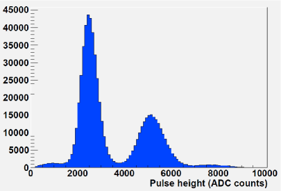
Narrow lines are expected in most cases to be unpolarized. Therefore a high spectral resolution is not required for the science of POLARIX. A moderate energy resolution of the order of 30 could be suitable to perform energy resolved polarimetry of source continua. Nevertheless, since the modulation factor and the efficiency are a relatively fast function of the energy, better energy resolution would help to disentangle the energy and polarimetric information. With the energy resolution provided by the GEM we hope to reach a resolution of at least 20 (@6keV). In fig.28) a spectrum (2.6 keV, 5.2 keV and 7.8 keV), obtained by using our calibration facility, is shown (Muleri2010 ,Muleri2008b )
7.5 Timing performances
The signal from the GEM is intrinsically very fast. The timing capability is limited by the shaping time of the electronic chains, required for low noise. This is still far superior than any scientific requirement. We fixed a timing resolution of 8 s that preserves a large margin of discovery. In order to synchronize the UT with OBT, POLARIX will have a GPS which allows a synchronization at the level of 1-2 s.
8 Observing capability
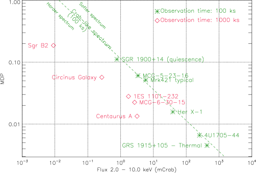
POLARIX is a mission totally dedicated to X-ray polarimetry. This important sub-topics of X-ray Astronomy, is always performed in the ’source dominated’ regime, given the large number of source counts necessary to be collected for a sensitive measurement. The MDP, in the 2-10 keV energy band, with s of observation is 3 for a source of 10 mCrab and it scales down simply with . It is therefore possible to increase the sensitivity by observing with a long pointing (one week/10 days) when required by dim sources. In the following we provide estimates of the MDP with reasonable observing time for different classes of celestial sources.
-
•
Magnetars are expected to be highly polarized for their large magnetic field. Bright magnetars, like SGR1900+14 (MDP of 10 in 100 ks when in quiescence) can be looked at to start searching for QED effects and other very interesting effects, as for instance the presence of axions (Lai & Heyl 2007 Lai2006 ), the elusive particles which are candidates for the main dark matter component.
-
•
The nebulae around , namely Sgr B2 and Sgr C, could be, actually, studied with a 10 days long pointing: X-ray polarimetry with POLARIX thanks to its rather good spacial resolution would solve the puzzle of the origin of their X-ray emission most probably due to past activity of the central galaxy black hole. In the case of Sgr B2 a MDP of about can be obtained with 1 Ms observation.
-
•
The angular resolution and the sensitivity of POLARIX would allow us to perform a spatially resolved X-ray polarimetry of the prototype of the PWNe, the Crab Nebula and Pulsar. The FoV of POLARIX allows us to perform imaging polarimetry of Crab Nebula within a single observation. It would then be possible to separate the torus emission from the jets integrating the X-ray polarization in a few independent regions. X-ray polarimetry would be useful to start to clarify the role of the magnetic field and of the particle flow in PWNe. Vela pulsar region which shows similarity with the Crab nebula could be also studied and X-ray polarimetry would be performed in two independent regions.
-
•
X-ray polarimetry of thermal emission from Microquasars hosting a Black Hole derived from the accretion disk can be performed in a very detailed way by POLARIX. The X-ray position angle and degree of polarization could therefore be studied as a function of energy providing information on the spinning of the black hole. Actually the best source to search for this effect is indeed GRS1915+105 (see figure 11(a) and 11(b)), a bright Microquasar whose 2-10 keV emission is, when in high state, dominated by thermal emission. Moreover, the source is highly inclined (70 degrees, Mirabel Rodriguez 1994 Mirabel1994 ), and therefore the polarization degree is expected to be high. GRS1915+105 can be studied at level of 0.34 in one day of observation. The possibility to perform X-ray polarimetry simultaneously to radio emission will allow the study of the interaction between the jet, the corona and the accretion disk. Polarization from Cyg X-1, Cyg-X3, J1655-40 and SS-433 could be studied in short interval of time allowing variability studies. Sources like Cyg X-1 (black hole) and 4U1705-04 (neutron star) show clear evidence for an accretion disc, they are bright enough to search for polarization less than 1 in 100 ks.
-
•
Pulsators are provided with a magnetic field of the order of 1012 Gauss. X-rays are therefore expected to be highly polarized especially at energy close to cyclotron lines. Energy resolved and phase resolved polarimetry can be performed by POLARIX at level of 1 in the first minumum and in the first part of the ascent for Vela X-1 the prototype of X-ray pulsators. Polarimetry not energy or phase resolved would fail to detect polarization because of the variation of the angular phase as was the case for OSO 8. As in the case of PWNe the swing of polarization angle with the angular phase will help to fix the angle between the magnetic and the rotation axis. Energy dependent polarimetry with POLARIX can confirm or disprove this scenario in a number of bright X-ray pulsars (e.g. Vela X-1, Her X-1, Cen X-3, A0535+26, etc.) by searching for polarization as low as a few percent in several phase bins and different energy bins.
-
•
Cataclismic Variable (CVs) can polarize the radiation either because of the reflection on the WD surface (Matt et al., 2004 Matt2004 ) of X-rays produced by the shocked accreting column or because they are scattered by the electrons which precipitate onto the White Dwarf (Wu 2010 Wu2010 ). In the latter case for particular geometry the polarization can be as high as 8 . Am Her can be as bright as 5 mCrab providing a MDP of about 5 in s of observation. A smaller MDP can be obtained with a longer pointing.
-
•
Regarding millisecond X-ray pulsar (MSP), POLARIX is sensitive enough to study its X-ray polarization. The quiescent emission of MSPs is usually rather weak, but still allowing for meaningful measurements of polarization with POLARIX (e.g. MDP of 3.7 in 100 ks for SAX1808.4-3658, which becomes 1.2 when in outburst).
-
•
In radio quiet AGN the corona play a crucial role in producing X-ray. The models can be tested with POLARIX at least for the brightest objects. Actually in the case of IC4329A, NGC5006 and MCG-5-23-16, MDP of a few percent can be reached in 100 ks, enough for a first test of the Comptonization model. In Compton-thick AGN, the reflection component dominates the 2-10 keV band. The brightest of such sources is the Circinus Galaxy (Matt et al. 1996Matt1996 ) for which a MDP of about 6 can be reached in a 1 Ms observation.
-
•
Blazars are among the most promising sources for X-ray polarimetry. Mkn421, for example, shows its X-ray emission in the synchrotron peak, therefore a high polarization is expected. When in flare Mrk421 will be observed with a MDP of 1 in s while in a typical state it will be observed with a MDP of . Multi-wavelength polarimetric observation could help to study the magnetic field and its microvariability and the energy distribution of the emitting particles. The case of 3C 454.3 is different, X-ray emission lies in the inverse Compton peak. The inverse Compton can be modelled either as Synchrotron Self Compton (the jet up-scatters soft synchrotron photons), or as External Compton from seed soft photon not produced in the jet scattered from the jet itself. POLARIX would provide a clue in disentangling between the two models and provide a clue about the physical status of the electron in the jet and may be providing an insight on the origin of the soft photons. POLARIX will be able to detect X-ray polarization at level of 3 in 10 day of observation from 3C 454.3. Many blazars are bright enough to allow a significant polarization measurement with POLARIX (MDP of a few percent in 100 ks). In non Blazar radio galaxy at least two sources, Centarus A and 3C 273, are bright enough to perform an energy-dependent polarimetry with POLARIX down to a few percent in a few days exposure.
More exotic physics can be studied with POLARIX. Very stringent upper limits on Quantum Gravity in the loop representation can be derived by observing distant blazars. With an observation of 106 s, values of down to 310-10 can be measured with POLARIX using e.g. the known Blazar 1ES1101+232, at z=0.186, with clear synchrotron spectrum and high optical polarization, assuming it has a 10 polarization degree in the X-ray band.
We are confident that the number of celestial sources in each class with measurable polarization angle and degree discussed above for a pathfinder mission will adequately fill the planned one year of satellite operation in orbit. However the sensitivity of POLARIX would allow the extension of this allocated time for sensitive measurement of sources within each class.
Acknowledgements.
The first studies of POLARIX were supported by ASI contract I/088/060 for which we thank Elisabetta Cavazzuti. The phase A study was supported by ASI contract I/016/08/0 . We thank Maria Cristina Falvella, Donatella Frangipane, Elisabetta Tommasi, Simona Zoffoli, Marino Crisconio, Paolo Giommi, Francesco Longo, Fabio D’Amico, Jean Sabbagh, Giancarlo Varacalli and Valeria Catalano from ASI for the effective and cooperative effort during all the study. We also acknowledge the support of ASI contract I/012/08/0 and Maria Barbara Negri. We also acknowledge the contrbution of large teams of Thales Alenia Space Italy and of Telespazio. A special thanks to Volker Liebig, Director of Earth Observation Programmes of ESA, for considering the possibility of making available to POLARIX spare parts of the GOCE mission.References
- (1) Novick, R., Weisskopf, M.C., Berthelsdorf, R., Linke, R., Wolff, R.S.: Detection of X-Ray Polarization of the Crab Nebula. ApJ174, L1 (1972)
- (2) Weisskopf, M.C., Cohen, G.G., Kestenbaum, H.L., Long, K.S., Novick, R., Wolff, R.S.: Measurement of the X-ray polarization of the Crab Nebula. ApJ208, L125 (1976)
- (3) Weisskopf, M.C., Silver, E.H., Kestenbaum, H.L., Long, K.S., Novick, R.: A precision measurement of the X-ray polarization of the Crab Nebula without pulsar contamination. ApJ220, L117 (1978). DOI 10.1086/182648
- (4) Hughes, J.P., Long, K.S., Novick, R.: A search for X-ray polarization in cosmic X-ray sources. ApJ280, 255 (1984). DOI 10.1086/161992
- (5) Long, K.S., Chanan, G.A., Ku, W., Novick, R.: The linear X-ray polarization of Scorpius X-1. ApJ232, L107–L110 (1979). DOI 10.1086/183045
- (6) Coburn, W., Boggs, S.E.: Polarization of the prompt -ray emission from the -ray burst of 6 December 2002. Nature423, 415–417 (2003). DOI 10.1038/nature01612
- (7) Wigger, C., Hajdas, W., Arzner, K., Güdel, M., Zehnder, A.: Polarization from GRB021206: No constraints from reanalysis of RHESSI data. Nuovo Cimento C Geophysics Space Physics C 28, 265–+ (2005). DOI 10.1393/ncc/i2005-10036-2
- (8) Dean, A.J., Clark, D.J., Stephen, J.B., McBride, V.A., Bassani, L., Bazzano, A., Bird, A.J., Hill, A.B., Shaw, S.E., Ubertini, P.: Polarized Gamma-Ray Emission from the Crab. Science 321, 1183 (2008). DOI 10.1126/science.1149056
- (9) Forot, M., Laurent, P., Grenier, I.A., Gouiffès, C., Lebrun, F.: Polarization of the Crab Pulsar and Nebula as Observed by the INTEGRAL/IBIS Telescope. ApJ688, L29–L32 (2008). DOI 10.1086/593974
- (10) Costa, E., Soffitta, P., Bellazzini, R., Brez, A., Lumb, N., Spandre, G.: An efficient photoelectric X-ray polarimeter for the study of black holes and neutron stars. Nature411, 662 (2001)
- (11) Bellazzini, R., Spandre, G., Minuti, M., Baldini, L., Brez, A., Cavalca, F., Latronico, L., Omodei, N., Massai, M.M., Sgro’, C., Costa, E., Soffitta, P., Krummenacher, F., de Oliveira, R.: Direct reading of charge multipliers with a self-triggering CMOS analog chip with 105 k pixels at 50 m pitch. Nuclear Instruments and Methods in Physics Research A 566, 552 (2006). DOI 10.1016/j.nima.2006.07.036
- (12) The Pierre Auger Collaboration: Correlation of the Highest-Energy Cosmic Rays with Nearby Extragalactic Objects. Science 318, 938– (2007). DOI 10.1126/science.1151124
- (13) Weisskopf, M.C., Hester, J.J., Tennant, A.F., Elsner, R.F., Schulz, N.S., Marshall, H.L., Karovska, M., Nichols, J.S., Swartz, D.A., Kolodziejczak, J.J., O’Dell, S.L.: Discovery of Spatial and Spectral Structure in the X-Ray Emission from the Crab Nebula. ApJ536, L81 (2000). DOI 10.1086/312733
- (14) Mirabel, I.F., Rodriguez, L.F.: A Superluminal Source in the Galaxy. Nature371, 46 (1994). DOI 10.1038/371046a0
- (15) Belloni, T., Mendez, M., King, A.R., van der Klis, M., van Paradijs, J.: An Unstable Central Disk in the Superluminal Black Hole X-Ray Binary GRS 1915+105. ApJ479, L145 (1997). DOI 10.1086/310595
- (16) Orosz, J.A., Bailyn, C.D.: Optical Observations of GRO J1655-40 in Quiescence. I. A Precise Mass for the Black Hole Primary. ApJ477, 876–+ (1997). DOI 10.1086/303741
- (17) Aharonian, F.: Relativistic Jets as Powerful Particle Accelerators and Gamma-ray Emitters. In: Bulletin of the American Astronomical Society, Bulletin of the American Astronomical Society, vol. 38, pp. 362–+ (2006)
- (18) Nagae, O., Kawabata, K.S., Fukazawa, Y., Okazaki, A., Isogai, M.: Optical Spectropolarimetry of Three microquasars, Cyg X-1, LS 5039, LS I +61d 303. In: Y.F. Yuan, X.D. Li, D. Lai (eds.) Astrophysics of Compact Objects, American Institute of Physics Conference Series, vol. 968, pp. 328–330 (2008). DOI 10.1063/1.2840421
- (19) Mirabel, I.F.: Black holes: from stars to galaxies. In: V. Karas, G. Matt (eds.) IAU Symposium, IAU Symposium, vol. 238, pp. 309–314 (2007). DOI 10.1017/S1743921307005224
- (20) Celotti, A., Matt, G.: Polarization Properties of Synchrotron Self-Compton Emission. MNRAS268, 451–+ (1994)
- (21) Begelman, M.C., Sikora, M.: Inverse Compton scattering of ambient radiation by a cold relativistic jet - A source of beamed, polarized continuum in blazars? ApJ322, 650–661 (1987). DOI 10.1086/165760
- (22) Poutanen, J.: Relativistic jets in blazars: Polarization of radiation. ApJS92, 607–609 (1994). DOI 10.1086/192024
- (23) Grandi, P., Palumbo, G.G.C.: Jet and Accretion-Disk Emission Untangled in 3C 273. Science 306, 998–1002 (2004). DOI 10.1126/science.1101787
- (24) Grandi, P., Palumbo, G.G.C.: Broad-Line Radio Galaxies: Jet Contribution to the Nuclear X-Ray Continuum. ApJ659, 235–240 (2007). DOI 10.1086/510769
- (25) Warner, B.: Cataclysmic variable stars (1995)
- (26) Matt, G.: X-ray polarization properties of the accretion column in magnetic CVs. A&A423, 495–500 (2004). DOI 10.1051/0004-6361:20035649
- (27) McNamara, A.L., Kuncic, Z., Wu, K.: X-ray polarization signatures of Compton scattering in magnetic cataclysmic variables. MNRAS386, 2167–2172 (2008). DOI 10.1111/j.1365-2966.2008.13174.x
- (28) Viironen, K., Poutanen, J.: Light curves and polarization of accretion- and nuclear-powered millisecond pulsars. A&A426, 985–997 (2004). DOI 10.1051/0004-6361:20041084
- (29) Meszaros, P., Novick, R., Szentgyorgyi, A., Chanan, G.A., Weisskopf, M.C.: Astrophysical implications and observational prospects of X-ray polarimetry. ApJ324, 1056 (1988). DOI 10.1086/165962
- (30) Haardt, F., Matt, G.: X-ray polarization in the two-phase model for AGN and X-ray binaries. MNRAS261, 346–352 (1993)
- (31) Poutanen, J., Vilhu, O.: Compton scattering of polarized light in two-phase accretion discs. A&A275, 337–+ (1993)
- (32) Matt, G., Costa, E., Perola, G.C., Piro, L.: X ray polarization of the reprocessed emission from accretion disk in Seyfert galaxies. In: J. Hunt, B. Battrick (eds.) Two Topics in X-Ray Astronomy, Volume 1: X Ray Binaries. Volume 2: AGN and the X Ray Background, ESA Special Publication, vol. 296, pp. 991–993 (1989)
- (33) Antonucci, R.: Unified models for active galactic nuclei and quasars. ARA&A31, 473–521 (1993). DOI 10.1146/annurev.aa.31.090193.002353
- (34) Urry, C.M., Padovani, P.: Unified Schemes for Radio-Loud Active Galactic Nuclei. PASP107, 803–+ (1995). DOI 10.1086/133630
- (35) Sunyaev, R.A., Markevitch, M., Pavlinsky, M.: The center of the Galaxy in the recent past - A view from GRANAT. ApJ407, 606–610 (1993). DOI 10.1086/172542
- (36) Koyama, K., Maeda, Y., Sonobe, T., Takeshima, T., Tanaka, Y., Yamauchi, S.: ASCA View of Our Galactic Center: Remains of Past Activities in X-Rays? PASJ48, 249–255 (1996)
- (37) Churazov, E., Sunyaev, R., Sazonov, S.: Polarization of X-ray emission from the Sgr B2 cloud. MNRAS330, 817–820 (2002). DOI 10.1046/j.1365-8711.2002.05113.x
- (38) Koyama, K., Inui, T., Matsumoto, H., Tsuru, T.G.: A Time-Variable X-Ray Echo: Indications of a Past Flare of the Galactic-Center Black Hole. PASJ60, 201–+ (2008)
- (39) Muno, M.P., Baganoff, F.K., Brandt, W.N., Park, S., Morris, M.R.: Discovery of Variable Iron Fluorescence from Reflection Nebulae in the Galactic Center. ApJ656, L69–L72 (2007). DOI 10.1086/512236
- (40) Heisemberg, W., Euler, H.: Zeischrift fur Physik 98, 714 (1936)
- (41) van Adelsberg, M., Lai, D.: Atmosphere models of magnetized neutron stars: QED effects, radiation spectra and polarization signals. MNRAS373, 1495–1522 (2006). DOI 10.1111/j.1365-2966.2006.11098.x
- (42) Stark, R.F., Connors, P.A.: Observational test for the existence of a rotating black hole in CYG X-1. Nature266, 429 (1977)
- (43) Connors, P.A., Stark, R.F., Piran, T.: Polarization features of X-ray radiation emitted near black holes. ApJ235, 224 (1980). DOI 10.1086/157627
- (44) Dovčiak, M., Muleri, F., Goosmann, R.W., Karas, V., Matt, G.: Thermal disc emission from a rotating black hole: X-ray polarization signatures. MNRAS391, 32–38 (2008). DOI 10.1111/j.1365-2966.2008.13872.x
- (45) Li, L., Narayan, R., McClintock, J.E.: Inferring the Inclination of a Black Hole Accretion Disk from Observations of its Polarized Continuum Radiation. ApJ691, 847–865 (2009). DOI 10.1088/0004-637X/691/1/847
- (46) Schnittman, J.D., Krolik, J.H.: X-ray Polarization from Accreting Black Holes: The Thermal State. ApJ701, 1175–1187 (2009). DOI 10.1088/0004-637X/701/2/1175
- (47) Fabian, A.C., Iwasawa, K., Reynolds, C.S., Young, A.J.: Broad Iron Lines in Active Galactic Nuclei. PASP112, 1145–1161 (2000). DOI 10.1086/316610
- (48) Miniutti, G., Fabian, A.C.: A light bending model for the X-ray temporal and spectral properties of accreting black holes. MNRAS349, 1435–1448 (2004). DOI 10.1111/j.1365-2966.2004.07611.x
- (49) Dovčiak, M., Karas, V., Matt, G.: Polarization signatures of strong gravity in active galactic nuclei accretion discs. MNRAS355, 1005–1009 (2004). DOI 10.1111/j.1365-2966.2004.08396.x
- (50) Amelino-Camelia, G.: Phenomenology of Planck-scale Lorentz-symmetry test theories. New Journal of Physics 6, 188–+ (2004). DOI 10.1088/1367-2630/6/1/188
- (51) Gambini, R., Pullin, J.: Nonstandard optics from quantum space-time. Phys. Rev. D59(12), 124,021 (1999)
- (52) Gleiser, R.J., Kozameh, C.N.: Astrophysical limits on quantum gravity motivated birefringence. Phys. Rev. D64(8), 083,007–+ (2001). DOI 10.1103/PhysRevD.64.083007
- (53) Kaaret, P.: X-ray clues to viability of loop quantum gravity. Nature427, 287 (2004)
- (54) Fan, Y.Z., Wei, D.M., Xu, D.: -ray burst ultraviolet/optical afterglow polarimetry as a probe of quantum gravity. MNRAS376, 1857–1860 (2007). DOI 10.1111/j.1365-2966.2007.11576.x
- (55) Maccione, L., Liberati, S., Celotti, A., Kirk, J.G., Ubertini, P.: -ray polarization constraints on Planck scale violations of special relativity. Phys. Rev. D78(10), 103,003–+ (2008). DOI 10.1103/PhysRevD.78.103003
- (56) Citterio, O., Campano, S., Conconi, P., Ghigo, M., Mazzoleni, F., Poretti, E., Conti, G., Cusumano, G., Sacco, B., Brauninger, H., Burkert, W., Egger, R., Castelli, C.M., Willingale, R.: Characteristics of the flight model optics for the JET-X telescope onboard the Spectrum-X-Gamma satellite. In: R.B. Hoover, A.B. Walker (eds.) Society of Photo-Optical Instrumentation Engineers (SPIE) Conference Series, Society of Photo-Optical Instrumentation Engineers (SPIE) Conference Series, vol. 2805, pp. 56–65 (1996)
- (57) Moretti, A., Campana, S., Mineo, T., Romano, P., Abbey, A.F., Angelini, L., Beardmore, A., Burkert, W., Burrows, D.N., Capalbi, M., Chincarini, G., Citterio, O., Cusumano, G., Freyberg, M.J., Giommi, P., Goad, M.R., Godet, O., Hartner, G.D., Hill, J.E., Kennea, J., La Parola, V., Mangano, V., Morris, D., Nousek, J.A., Osborne, J., Page, K., Pagani, C., Perri, M., Tagliaferri, G., Tamburelli, F., Wells, A.: In-flight calibration of the Swift XRT Point Spread Function. In: O.H.W. Siegmund (ed.) Society of Photo-Optical Instrumentation Engineers (SPIE) Conference Series, Society of Photo-Optical Instrumentation Engineers (SPIE) Conference Series, vol. 5898, pp. 360–368 (2005). DOI 10.1117/12.617164
- (58) Romano, P., Cusumano, G., Campana, S., Mangano, V., Moretti, A., Abbey, A.F., Angelini, L., Beardmore, A., Burrows, D.N., Capalbi, M., Chincarini, G., Citterio, O., Giommi, P., Goad, M.R., Godet, O., Hartner, G.D., Hill, J.E., Kennea, J., LaParola, V., Mineo, T., Morris, D., Nousek, J.A., Osborne, J., Page, K., Pagani, C., Perri, M., Tagliaferri, G., Tamburelli, F., Wells, A.: In-flight calibration of the SWIFT XRT effective area. In: O.H.W. Siegmund (ed.) Society of Photo-Optical Instrumentation Engineers (SPIE) Conference Series, Society of Photo-Optical Instrumentation Engineers (SPIE) Conference Series, vol. 5898, pp. 369–376 (2005). DOI 10.1117/12.616974
- (59) Bellazzini, R., Spandre, G., Minuti, M., Baldini, L., Brez, A., Latronico, L., Omodei, N., Razzano, M., Massai, M.M., Pesce-Rollins, M., Sgró, C., Costa, E., Soffitta, P., Sipila, H., Lempinen, E.: A sealed Gas Pixel Detector for X-ray astronomy. Nuclear Instruments and Methods in Physics Research A 579, 853 (2007). DOI 10.1016/j.nima.2007.05.304
- (60) Muleri, F., Soffitta, P., Bellazzini, R., Brez, A., Costa, E., Fabiani, S., Frutti, M., Minuti, M., Negri, M.B., Pascale, P., Rubini, A., Sindoni, G., Spandre, G.: A very compact polarizer for an X-ray polarimeter calibration. In: Proc. SPIE, vol. 6686, p. 668610 (2007). DOI 10.1117/12.734647
- (61) Weisskopf, M.C., Elsner, R.F., Kaspi, V.M., O’Dell, S.L., Pavlov, G.G., Ramsey, B.D.: X-Ray Polarimetry and Its Potential Use for Understanding Neutron Stars. In: W. Becker (ed.) Astrophysics and Space Science Library, Astrophysics and Space Science Library, vol. 357, pp. 589–+ (2009)
- (62) Weisskopf, M.C., Elsner, R.F., O’Dell, S.L.: On understanding the figures of merit for detection and measurement of x-ray polarization. ArXiv e-prints, Proceed. of SPIE conference, San Diego (2010)
- (63) Muleri, F., Soffitta, P., Baldini, L., Bellazzini, R., Brez, A., Costa, E., Fabiani, S., Krummenacher, F., Latronico, L., Lazzarotto, F., Minuti, M., Pinchera, M., Rubini, A., Sgró, C., Spandre, G.: Spectral and polarimetric characterization of the Gas Pixel Detector filled with dimethyl ether. Nuclear Instruments and Methods in Physics Research A 620, 285–293 (2010)
- (64) Muleri, F., Soffitta, P., Bellazzini, R., Brez, A., Costa, E., Frutti, M., Mastropietro, M., Morelli, E., Pinchera, M., Rubini, A., Spandre, G.: A versatile facility for the calibration of x-ray polarimeters with polarized radiation. In: Proc. SPIE, vol. 7011-84 (2008)
- (65) Lai, D., Heyl, J.: Probing axions with radiation from magnetic stars. Phys. Rev. D74(12), 123,003–+ (2006). DOI 10.1103/PhysRevD.74.123003
- (66) Wu, K., McNamara, A., Kuncic, Z.: X-ray polarization from accreting white-dwarf and associated systems. In: To be published in Proc. of Conference ’ The coming of age of X-ray polarimetry’ (2010)
- (67) Matt, G., Fiore, F., Perola, G.C., Piro, L., Fink, H.H., Grandi, P., Matsuoka, M., Oliva, E., Salvati, M.: A reflection-dominated X-ray spectrum discovered by ASCA in the Circinus galaxy. MNRAS281, L69–L73 (1996)