Collimation with hollow electron beams
Abstract
A novel concept of controlled halo removal for intense high-energy beams in storage rings and colliders is presented. It is based on the interaction of the circulating beam with a 5-keV, magnetically confined, pulsed hollow electron beam in a 2-m-long section of the ring. The electrons enclose the circulating beam, kicking halo particles transversely and leaving the beam core unperturbed. By acting as a tunable diffusion enhancer and not as a hard aperture limitation, the hollow electron beam collimator extends conventional collimation systems beyond the intensity limits imposed by tolerable losses. The concept was tested experimentally at the Fermilab Tevatron proton-antiproton collider. The first results on the collimation of 980-GeV antiprotons are presented.
pacs:
29.20.db, 29.27.-a, 41.75.-i, 41.85.-p, 41.85.SiIn high-energy particle accelerators and storage rings, the collimation system must protect equipment from intentional and accidental beam aborts by intercepting particle losses Tev_coll ; LHC_coll ; Seidel:1994 . Its functions include controlling and reducing the beam halo, which is continually replenished by various processes such as beam-gas scattering, intrabeam scattering, electrical noise in the accelerating cavities, ground motion, betatron resonances, and beam-beam collisions. Uncontrolled losses of even a small fraction of the circulating beam can damage components, quench superconducting magnets, or produce intolerable experimental backgrounds. Collimators also serve as a diagnostic tool for fundamental machine measurements, such as transverse admittances, beam vibrations, and diffusion rates.
Conventional collimation schemes are based on scatterers and absorbers, possibly incorporating several stages. The primary collimators (or targets) are the devices closest to the beam. They generate random transverse kicks mainly via multiple Coulomb scattering. In the Tevatron, the primary collimators are 5-mm tungsten plates positioned about 5 standard deviations () away from the beam axis. The random multiple-scattering kick has a root mean square (r.m.s.) of for 980-GeV protons. The betatron oscillation amplitude of the affected particles increases, and a large fraction of them is captured by the secondary collimators (or absorbers), suitably placed around the ring. In the Tevatron, the absorbers are 1.5-m steel blocks at 6.
The conventional two-stage system offers robust shielding of sensitive components and it is very efficient in reducing beam-related backgrounds at the experiments. However, it has limitations. In high-power accelerators, the minimum distance between the collimator and the beam axis is limited by instantaneous loss rates, radiation damage, and by the electromagnetic impedance of the device. Moreover, beam jitter, caused by ground motion and other vibrations and partly mitigated by active orbit feedback, can cause periodic bursts of losses at aperture restrictions.
| (a) | (b) |
 |
 |
 |
 |
| (c) | (d) |
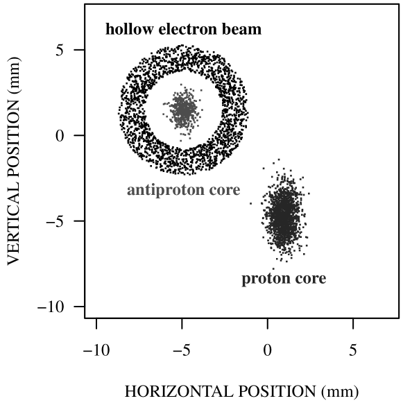
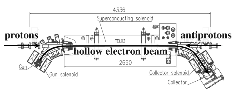
The object of this research is whether the hollow electron beam collimator (HEBC) is a viable complement to conventional systems in high-intensity storage rings and colliders, such as the Tevatron or the LHC HEBC_concept ; Shiltsev:EPAC:2008 ; Smith:PAC:2009 ; HEBC_previous . In a hollow electron beam collimator, electrons enclose the circulating beam over a 2-m section of the ring immersed in a 1 T to 3 T solenoidal field (Figure 1). The electron beam is generated by a pulsed 5-kV electron gun and it is transported with strong axial magnetic fields, in an arrangement similar to electron cooling Parkhomchuk:RAST:2008 and electron lenses TEL . Its size in the interaction region is controlled by varying the ratio between the magnetic fields in the main solenoid and in the gun solenoid. Halo particles experience nonlinear transverse kicks and are driven towards the collimators. If the hollow current distribution is axially symmetric there are no electric or magnetic fields inside and the beam core is unperturbed. A magnetically confined electron beam is stiff, and experiments with electron lenses show that it can be placed very close to, and even overlap with the circulating beam. Another advantage is that, contrary to conventional systems, no nuclear breakup is generated in the case of ion collimation.
The transverse kick experienced by particles of magnetic rigidity traversing a hollow electron beam at a distance from its axis depends on the enclosed electron current and on the length of the interaction region:
| (1) |
where is the electron velocity and is the particle velocity. The sign applies when the magnetic and electric forces have the same direction. For example, in a setup similar to that of the Tevatron electron lenses (, , , ), the corresponding radial kick is for 980-GeV counterpropagating antiprotons. The intensity of the transverse kicks is small and tunable: the device acts more like a soft scraper or a diffusion enhancer, rather than a hard aperture limitation. Because the kicks are not random in space or time, resonant excitation is possible if faster removal is desired.
Analytical expressions for the current distribution were used to estimate the effectiveness of the HEBC on a proton beam. They were included in tracking codes such as STRUCT, LIFETRAC, and SixTrack tracking_codes to follow core and halo particles as they propagate in the machine lattice. These codes are complementary in their treatment of apertures, field nonlinearities, and beam-beam interactions. Preliminary simulations suggested that effects would be observable and that measurements would be compatible with normal collider operations.
The concept was tested experimentally in the Fermilab Tevatron collider. In the Tevatron, 36 proton bunches collide with 36 antiproton bunches at an energy of 980 GeV per beam. Each particle species is arranged in 3 trains of 12 bunches each. Initial beam intensities are typically and . Beam lifetimes range between 10 h and 100 h. There are 2 head-on interaction points, corresponding to the CDF and the DZero experiments. The maximum luminosity is . The machine operates with betatron tunes near 20.58.
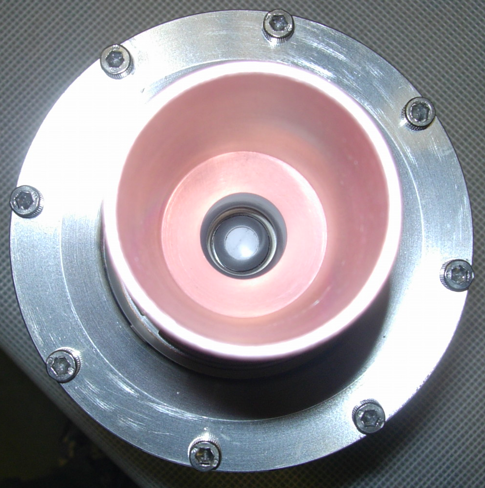
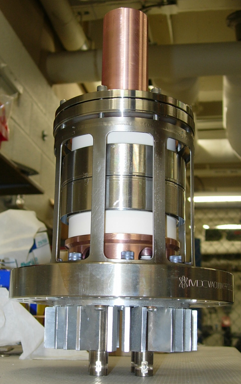
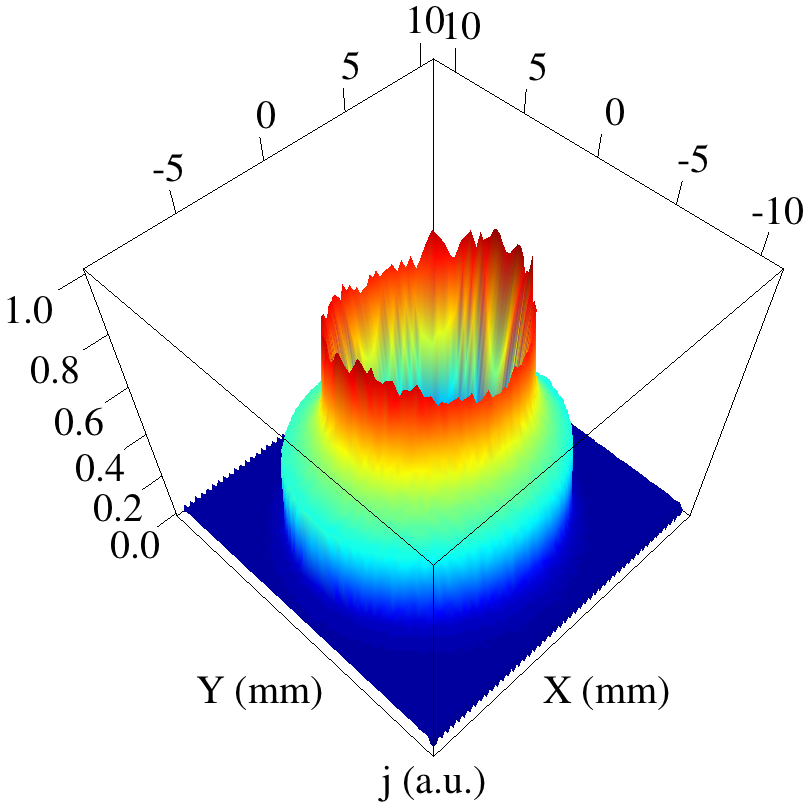
A 15-mm-diameter hollow electron gun was designed and built (Figure 2). It is based on a tungsten dispenser cathode with a 9-mm-diameter hole bored through the axis of its convex surface. The peak current delivered by this gun is 1.1 A at 5 kV. The current density profile was measured on a test stand by recording the current through a pinhole in the collector while changing the position of the beam in small steps. A sample measurement is shown in Figure 2. The gun was installed in one of the Tevatron electron lenses, where the pulsed electron beam could be synchronized with practically any bunch or group of bunches.
| mA | %/h | %/h | ||
|---|---|---|---|---|
| 0 | ||||
| 380 | ||||
| 366 | ||||
| 397 | ||||
| 436 | ||||
| 405 | ||||
| 410 | ||||
| 410 |
The behavior of the device and the response of the circulating beams were measured for different beam currents, relative alignments, hole sizes, pulsing patterns, and collimator system configurations. Here, we focus on a few representative experiments illustrating the main effects of the electron beam acting on antiproton bunches. Other important effects, such as collimation efficiencies, fluctuations in losses, and diffusion rates will be presented in a separate report. Antiprotons were chosen for two main reasons: their smaller transverse emittances (achieved by stochastic and electron cooling) made it possible to probe a wider range of confining fields and hole sizes; and the betatron phase advance between the electron lens and the absorbers is more favorable for antiproton collimation.
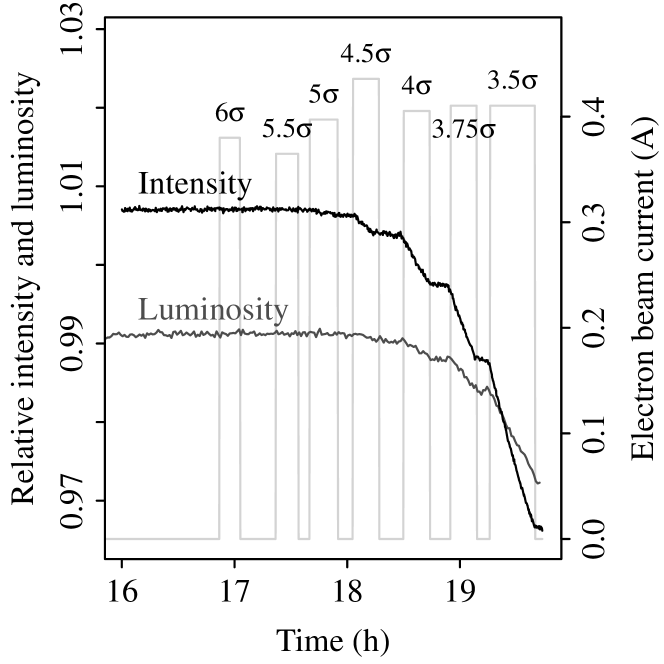
The first question we address is the particle removal rate. In the experiment described in Figure 3, the electron lens was aligned and synchronized with the second antiproton bunch train, and then turned on and off several times at the end of a collider store. The electron beam current was about 0.4 A and the radius of the hole was varied between 6 and 3.5, being the vertical r.m.s. beam size. The light-gray trace is the electron-lens current. To isolate the effect of the hollow beam, the ratio between the intensity of the affected train and the average intensity of the other two control trains is shown in Figure 3 (black trace). One can clearly see the smooth scraping effect. The corresponding average removal rates are collected in Table 1.
Whether there are any adverse effects on the core of the circulating beam is a concern, because the overlap region is not a perfect hollow cylinder, due to asymmetries in gun emission, to evolution under space charge of the hollow profile, and to the bends in the transport system. We approached the problem from four points of view. First, one can see from Figure 3 and Table 1 that no decrease in intensity was observed with large hole sizes, when the hollow beam was shadowed by the primary collimators. This implies that the circulating beam was not significantly affected by the hollow electron beam surrounding it, and that the effect on beam intensity of residual fields near the axis was negligible.

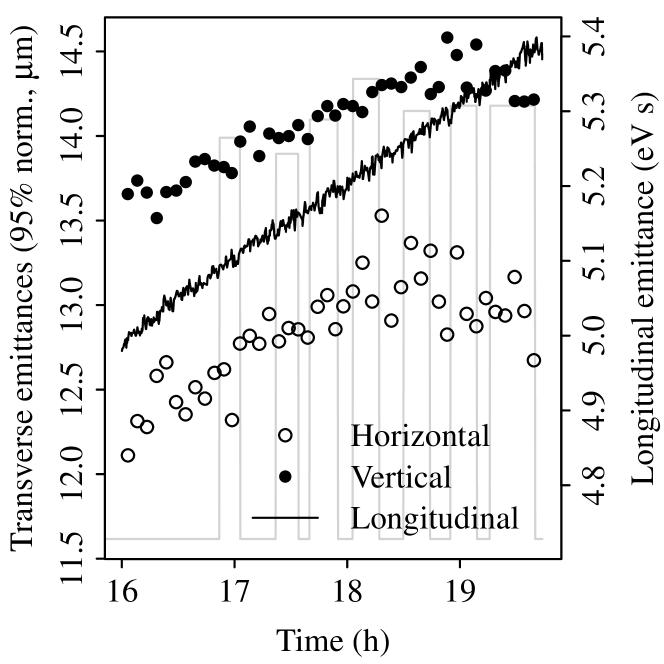
Secondly, one can observe the evolution of the emittances. Figure 4 shows the average emittances of the affected bunch train during the experiment of Figure 3. If there was emittance growth produced by the electron beam, it was much smaller than that driven by the other two main factors, namely intrabeam scattering and beam-beam interactions. As expected, for small hole sizes, suppression of the beam tails translated into a reduction in measured transverse emittances.
The effect of halo removal can also be observed by comparing beam scraping with the corresponding decrease in luminosity. Luminosity is proportional to the product of antiproton and proton populations, and inversely proportional to the overlap area. If antiprotons are removed uniformly and the other factors are unchanged, luminosity should decrease by the same relative amount. If the hollow beam causes emittance growth or proton loss, luminosity should decrease even more. A smaller relative change in luminosity is a clear indication that halo scraping is larger than core removal. In Figure 3, one can see how the luminosity for the affected bunch changed with time relative to the average luminosity of the control bunch trains. The gray trace is the ratio . The corresponding relative luminosity decay rates are reported in Table 1. The ratio between luminosity decay rates and intensity decay rates increased with decreasing hole size.
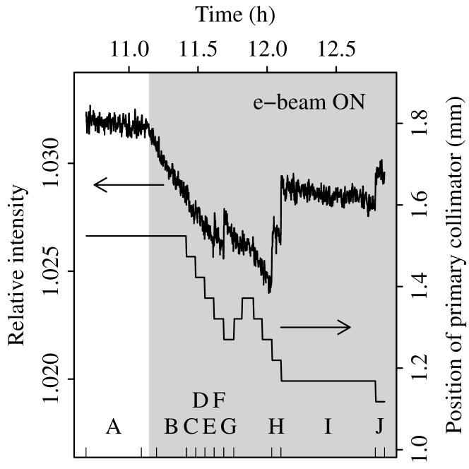
Finally, one can attempt to directly measure the particle removal rate as a function of amplitude. This was done with a collimator scan (Figure 5, top). A primary antiproton collimator was moved vertically in 50-micron steps towards the beam axis. All other collimators were retracted. The corresponding beam losses and decay rates were recorded. The electron lens was acting on the second bunch train with a peak current of 0.15 A and a hole size of 3.5, or 1.3 mm at the location of the collimator. The corresponding relative intensity decay rates as a function of collimator position are shown in the bottom plot of Figure 5. The effect of the electron lens for a given collimator position is represented by the difference between the A and B data sets. Data sets B through J correspond to different collimator positions, all with electron lens on. Particles are removed where electrons are, but as soon as the primary collimator shadows the electron beam, eliminating the halo at those amplitudes, the relative intensity decay rate of the affected bunch train goes back to the value it had with lens off. Even with such a small hole size, the effects of residual fields on the core appear to be negligible. The time evolution of losses during a collimator scan can also be used to measure changes in diffusion rate as a function of amplitude Seidel:1994 .
Losses generated by the electron lens were mostly deposited in the collimators, with small changes at the experiments. Alignment of the beams was crucial, and the procedures based on the electron-lens beam-position monitors were found to be reliable in spite of the different time structure of the electron and (anti)proton pulses. No instabilities or emittance growth were observed over the course of several hours at nominal antiproton intensities and electron beam currents up to 1 A in confining fields above 1 T in the main solenoid. Most of the studies were done parasitically during regular collider stores.
In summary, it was demonstrated that controlled particle removal in high-intensity storage rings and colliders with hollow electron beams is viable. The device complements and extends conventional collimation systems: particle removal is gradual and controllable, and the electron beam can be placed arbitrarily close to the circulating beam. To make the device more versatile, larger cathodes and higher electron beam currents appear to be feasible, and experimental tests in this direction are planned. Applicability to the Large Hadron Collider is also under study.
Acknowledgements.
The authors would like to thank R. Assmann and the CERN LHC Collimation Group, A. Drozhdin, N. Mokhov, and R. Moore of Fermilab, and V. Kamerdzhiev (Forschungszentrum Jülich, Germany) for discussions and insights; G. Saewert (Fermilab) for the design of the high-voltage modulator; M. Convery, C. Gattuso, and T. Johnson (Fermilab) for support during operation of the accelerator. Fermilab is operated by Fermi Research Alliance, LLC under Contract DE-AC02-07CH11359 with the United States Department of Energy. This work was partially supported by the U.S. LHC Accelerator Research Program (LARP).References
- (1) M. Church et al., in Proc. 1999 Part. Accel. Conf. (PAC99), New York, New York, p. 56; D. Still et al., in Proc. 29th ICFA Adv. Beam Dynamics Workshop (HALO03), Montauk, New York, AIP Conf. Proc. 693, p. 176 (2003).
- (2) O. Brüning et al. (ed.), LHC Design Report, Vol. I, Ch. 18, CERN-2004-003 (2004).
- (3) K.-H. Mess and M. Seidel, Nucl. Instr. Meth. Phys. Res. A 351, 279 (1994).
- (4) V. Shiltsev, in Proc. 3rd CARE-HHH-APD Workshop (LHC-LUMI-06), Valencia, Spain, p. 92, CERN-2007-002 (2007); Proc. CARE-HHH-APD Workshop (BEAM07), Geneva, Switzerland, p. 46, CERN-2008-005 (2007).
- (5) V. Shiltsev et al., Proc. 2008 Eur. Part. Accel. Conf. (EPAC08), Genoa, Italy, p. 292.
- (6) J. C. Smith et al., in Proc. 2009 Part. Accel. Conf. (PAC09), Vancouver, Canada, WE6RFP031.
- (7) G. Stancari et al., in Proc. 2010 Int. Part. Accel. Conf. (IPAC10), Kyoto, Japan, TUPEB076; Proc. 14th Adv. Accel. Concepts Workshop (AAC10), AIP Conf. Proc. 1299, 638 (2010); Proc. 2011 Part. Accel. Conf. (PAC11), New York, New York, MOP147.
- (8) V. V. Parkhomchuk and A. N. Skrinsky, Rev. Accel. Sci. Tech. 1, 237 (2008).
- (9) V. Shiltsev et al., Phys. Rev. Lett. 99, 244801 (2007); New J. Phys. 10, 043042 (2008); Phys. Rev. ST Accel. Beams 11, 103501 (2008); X.-L. Zhang et al., Phys. Rev. ST Accel. Beams 11, 051002 (2008).
- (10) I. Baishev et al., SSCL-MAN-0034 (1994); D. Shatilov et al., in Proc. 2005 Part. Accel. Conf. (PAC05), Knoxville, Tennessee, p. 4138; G. Robert-Demolaize et al., in Proc. 2005 Part. Accel. Conf. (PAC05), Knoxville, Tennessee, p. 4084.