Transmission Schemes based on Sum Rate Analysis in Distributed Antenna Systems
Abstract
In this paper, we study single cell multi-user downlink distributed antenna systems (DAS) where antenna ports are geographically separated in a cell. First, we derive an expression of the ergodic sum rate for the DAS in the presence of pathloss. Then, we propose a transmission selection scheme based on the derived expressions which does not require channel state information at the transmitter. Utilizing the knowledge of distance information from a user to each distributed antenna (DA) port, we consider the optimization of pairings of DA ports and users to maximize the system performance. Based on the ergodic sum rate expressions, the proposed scheme chooses the best mode maximizing the ergodic sum rate among mode candidates. In our proposed scheme, the number of mode candidates are greatly reduced compared to that of ideal mode selection. In addition, we analyze the signal to noise ratio cross-over point for different modes using the sum rate expressions. Through Monte Carlo simulations, we show the accuracy of our derivations for the ergodic sum rate. Moreover, simulation results with the pathloss modeling confirm that the proposed scheme produces the average sum rate identical to the ideal mode selection with significantly reduced candidates.
I Introduction
Wireless communication systems have been evolving to maximize data rates for satisfying demands on high speed data and multimedia services. One of key technologies in next generation communication systems is a multiple-input multiple-output (MIMO) method, which enables to increase spectral efficiency without requiring additional power or bandwidth consumption [1, 2, 3, 4]. Recently, a distributed antenna system (DAS) has been introduced as a new cellular communication structure for expanding coverage and increasing sum rates by having distributed antenna (DA) ports throughout a cell. The DAS is regarded as a potential solution for next generation wireless systems because of its power and capacity merit over conventional cellular systems which have centralized antennas at the center location [5].
Utilizing geographically separated antenna ports, many works have attempted to enhance the system performance of the DAS including the design of antenna locations [6] [7]. Most studies were focused on the uplink performance analysis to exploit its structurally simple feature [8, 9, 10]. Recently, the analysis for downlink was studied in [11] and [12] from an information theoretic point of view. Also, the downlink capacity under a single user scenario was investigated in [5] for the cases with and without perfect channel state information (CSI) at the transmitter. Recently, [13] and [14] presented downlink sum rate analysis and power allocation methods with large system limit using random matrix theory. However, it is difficult to understand the properties of practical finite systems with the results derived under the large system limit.
Unlike conventional MIMO systems, all DA ports in DAS have different channel characteristics since the signal from users to DA ports experiences independent large-scale fadings. Therefore, we can increase the ergodic sum rate of the DAS by coordinating a transmission technique for DA ports in the presence of the large-scale fadings. A representative work of transmission selection in DAS with a single user was made in [15] where an adaptive mode selection method is designed based on the received signal to noise ratio (SNR) from each DA port and the required quality-of-service (QoS) of the users. In [16], this result was extended to an uplink DAS scenario with two users and two DA ports, and an adaptive transmit-receive mode selection scheme was proposed. However, these works focused on the condition which satisfies the QoS requirement and mainly studied the error performance for transmission methods.
In this paper, we investigate a transmission scheme for multi-user multi DA port DAS to maximize the ergodic sum rate. There are several possible transmission modes depending on the pairings of users and DA ports. First, utilizing the user distance information, we derive an expression of the ergodic sum rate for various transmission modes. Then, we introduce a transmission selection scheme which adaptively determines the best transmission mode among mode candidates using only the knowledge of the distance from users to DA ports without requiring instantaneous CSI. Moreover, our proposed scheme significantly reduces the number of mode candidates without any loss of the ergodic sum rate performance. In addition, by applying an approximation to the derived ergodic sum rate expressions, we obtain the SNR cross-over points for different transmission modes, which provide helpful insights on the transmission mode selection. In the simulation section, we confirm the accuracy of the derived expressions by evaluating the cell averaged ergodic sum rate performance. Also, we show that the proposed scheme yields the performance identical to the ideal transmission selection case with much reduced candidates.
The remainder of the paper is organized as follows: In Section II, we present the channel model of DAS with single cell multi-user environments. Section III derives an ergodic sum rate expression for transmission modes. In Section IV, we propose transmission mode selection strategies based on the derived expressions and present analysis of the mode selection methods in Section V. We provide simulation results in Section VI. Finally, Section VII concludes this paper.
Throughout this paper, represents the expectation operation and denotes the maximum of and .
II System Model
We consider single cell downlink DAS environments with users and DA ports, all equipped with a single antenna as shown in Figure 1. In our analysis, it is assumed that instantaneous CSI is available only at the receiver side and each DA port has individual power constraint . We assume that all DA ports are physically connected with each other via dedicated channels such as fiber optics and an exclusive RF link. Moreover, we assume that all DA ports share user data and user distance information, but do not require the CSI of each user. The user distance information can be simply obtained by measuring the received signal strength indicator [17] and thus the amount of feedback is significantly reduced compared to the system which requires the instantaneous CSI.
The received signal for the -th user is written as
where denotes the propagation pathloss with the pathloss exponent due to the distance between the -th user and the -th DA port, equals the transmit power, ’s indicate independent and identically distributed complex Gaussian random variables with unit variance, stands for the transmitted symbol from the -th DA port with the average power , and represents the additive white Gaussian noise with variance for the -th user. In this paper, we consider DAS with circular antenna layout as in Figure 1. The cell radius is set to at center , and the -th DA port is located at for with as in [5].
Here, we assume that each DA port transmits the signal with its full power , or it is turned off. It was shown in [18] that such binary on/off power control maintains the optimal performance for instantaneous channel realizations in two-user environments. Although the binary power control may not be optimum in terms of the ergodic sum rate and for the systems with more than two users, we employ the binary power control for our system to simplify the operations. Investigation of the optimal power allocation for DAS is outside the scope of this paper, and remains as an interesting future work.
A main goal of this paper is to determine pairings of DA ports and their supporting users which maximize the ergodic sum rate for given user distance information. Let us denote the transmission mode
| (1) |
as the user index of DA ports where represents the user index supported by the -th DA port . Here, the index indicates that no user is supported by the corresponding DA. Moreover, we define the number of active users and active DA ports as and , respectively. Thus, should be less than or equal to , i.e., . In other words, the supported user indices of consist of non-zero distinct elements, and only DA ports have a non-zero user index in .
III Ergodic Sum Rate Analysis
In this section, we will study the statistical properties of the multi-user multi-DA ports DAS with given user distance information. The ergodic sum rate can be expressed as
| (2) |
where and indicate the signal to interference plus noise ratio (SINR) and the rate of the -th user, respectively.
From (1), let us define as the set of DA port indices supporting the -th user, as the set of all active DA port indices, and as the complement of in for and , respectively. For user , the signal from DA ports in is regarded as the desired signal, while the signal transmitted from DA ports in is treated as interference. Especially, when , which means that user is not supported by any DA port and thus is not an active user, the rate for the corresponding user is zero (). Note that only active users have non-zero rates. Then, the rate of the -th active user is generally represented as
| (3) | |||||
where and denote the instantaneous signal power and the interference plus noise power of user , respectively.
In what follows, we consider the probability density function (pdf) of each user’s SINR to derive a closed form of the ergodic sum rate. It is obvious from (3) that and follow a weighted Chi-squared distribution when , is fixed. Thus, the corresponding pdfs can be expressed as
| (4) |
and
| (5) |
Then, the ergodic sum rate is derived from (6) using integration formulas [19] as
where denotes the exponential integral. Finally, the ergodic sum rate expression for DAS can be obtained by substituting (III) into (2). Note that this is a function of SNR for given user location information.
As a simple example, we consider the DAS with two users and two DA ports (). First, for the case, there are two possible transmission modes, i.e., and . Similarly, for the single user transmission case (), there exist six cases of the transmission mode (i.e. , , , ,, ). In the former case, for example, indicates that user and user are supported by and , respectively, and the signal transmitted from is considered as interference to user . In this case, the supporting DA port index sets for each user are given as , , , and .
By plugging (III) into (2) with this setup, the ergodic sum rate expression for is written as
In contrast, for the single user transmission case of , it follows
A closed form of the ergodic sum rate for other modes can also be similarly obtained by using the above derived expressions. It should be emphasized that the derived ergodic sum rate has a generalized form with respect to the number of terms in the numerator and the denominator in (3). Thus, the derived expression can present the sum rate of DAS with arbitrary numbers of users and DA ports. It will be shown later in Section VI that our derived ergodic sum rate expressions accurately match with the simulation results.
IV Transmission Selection Strategies
In this section, we study the ideal mode selection and propose a simple transmission selection scheme for the ergodic sum rate maximization using the derived expression in the previous section.
IV-A Ideal Mode Selection
We first address the ideal mode selection which chooses the optimum transmission mode by exhaustive search. To this end, we compute the ergodic sum rates using (2) and (III) for all possible transmission modes with given user distance information. Then, we select the best mode which has the highest ergodic sum rate among them. In this mode selection problem, the pairings of active DA ports and the supported users become our main consideration to maximize the ergodic sum rate.
Now we examine the number of mode candidates for the ideal mode selection. First, for the single user transmission case (), it is obvious that supporting one user with all active DA ports always shows better performance than serving the user with fewer DA ports due to the increased array gain. For example, generates better sum rate compared to that of or because all DA ports are turned on and yield higher signal power.
Generalizing this to arbitrary and , the size of the set of mode candidates is given as , since the single user transmission modes with do not need to be included for the transmission mode selection problem. It is obvious that the number of mode candidates increases exponentially with , and thus the search size of the ideal mode selection may become prohibitive as and grow large. Instead, by using the user distance information, we can conceive more efficient transmission methods which determine the best transmission mode with reduced mode candidates.
IV-B Mode Selection based on Minimum Distance
In this subsection, we propose a transmission selection scheme which reduces the candidate size of the ideal mode selection. Motivated by the fact that the overall sum rate is determined mostly by the DA port with the nearest user, we introduce a new method based on the minimum distance where the number of mode candidates decreases dramatically for large and .
For the DAS with users and DA ports, we start with the transmission mode where each DA port serves the nearest user from itself with . Then, we turn off DA ports one by one with distinct combinations, and generate a mode candidate. Then, all these candidates are added to the mode candidate set . As mentioned before, we exclude modes with from since those modes have lower rates due to the reduced array gain. Instead, we add a mode serving one user with all of DA ports (i.e. and ) where the only user is chosen as the one who has the minimum distance among all users and DA ports. The algorithm is summarized in Table I.
Finally, the mode candidate set with size of is completed for the DAS, since out of DA on/off combinations, we have excluded modes with and added a single user transmission mode with . Then, after evaluating the ergodic sum rate for each candidate mode in using the expressions derived in Section III, we select the best mode which exhibits the maximum rate. It is clear that the number of candidates is reduced substantially compared to that of the ideal mode selection .
Note that the number of mode candidates for the proposed scheme is determined by the number of DA ports, and is independent of the number of users. As a result, the complexity of our proposed scheme is not affected by , unlike the ideal mode selection. Also, as the number of users and DA ports increase, a reduction in the number of mode candidates in the proposed scheme grows. For example, for , mode candidates are required for the ideal mode selection, while candidates are employed in our proposed selection scheme, which accounts for only of the original search size.
It should be emphasized again that our proposed scheme needs only the user distance information at each DA port and does not require the instantaneous CSI. Thus, the overhead associated with the CSI feedback can be avoided. It will be shown in Section VI that the proposed scheme based on the minimum distance shows the ergodic sum rate performance identical to the ideal transmission selection scheme.
V Analysis on Mode Selection
In the previous section, we have proposed a transmission mode selection scheme with substantially reduced number of candidates using the ergodic sum rate expression derived in Section III. Normally, different transmission modes exhibit different sum rate curve patterns. For example, for the DAS with , modes with show saturated sum rates at high SNR, while the performance of the single user transmission mode with increases as SNR grows large, and thus cross-over points exist in the sum rate curves with different modes. In this section, to provide insightful observations, we derive the SNR cross-over point of transmission modes and discuss the mode selection methods in detail. The derived ergodic sum rate expression in Section III contains a summation of exponential integral forms. It is difficult to compare the expressions with the sum of the exponential integrals, and thus the analysis of the mode selection is hard to obtain using exact expressions. For simple analysis, we compute the cross-over point with the approximated exponential integral for the system with two DA ports and two users. In this case, the number of transmission mode candidates for the ideal mode selection scheme is four in total with .
By applying an approximation of the exponential integral [20] to the ergodic sum rate expressions of the system with , the sum rate for is written as
| (8) |
where denotes the SNR as . Also, the rate for is written as
| (9) |
The approximated expressions for can be derived similarly.
To determine the cross-over point of the ergodic sum rate between and , we first let (8) and (9) equal. Then, it follows
| (10) |
Applying high SNR assumptions to both sides of (10) as
| (11) |
we notice that equation (11) has only one solution with respect to . Finally, the SNR cross-over point between transmission modes, , is computed using (11) as
| (12) |
Thus, the two user transmission mode is selected if the SNR is smaller than , while the single user transmission mode is chosen at SNR higher than . The cross-over point between and can be similarly computed as . This indicates that a single user transmission mode is expected to exhibit better performance compared to a two user transmission mode at high SNR region. The accuracy of our analysis will be verified numerically through the Monte Carlo simulations in Section VI.
Moreover, since the logarithm increases monotonically with its argument, a sum rate expression for in (9) is lower-bounded by
| (13) | |||||
Since the minimum distance user maximizes for the single user transmission, this indicates that a user should be determined based on the minimum distance between users and DA ports.
VI Simulation Results
In this section, we will confirm the accuracy of the derived ergodic sum rate expression and present the performance of the proposed mode selection scheme via Monte Carlo simulations. Throughout the simulation, the pathloss exponent and the cell radius are set to be and , respectively.111 With this setting, the cell edge users have a received SNR loss of compared to the cell center for the conventional pathloss modeling. The number of generated channel realizations is equal to .
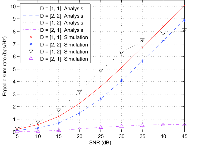
In Figure 2, we illustrate the ergodic sum rate of each transmission mode for the DAS with two users and two DA ports with fixed user locations. The location of two DA ports are set to and , and it is assumed that two users are located at () and (). From this figure, we can verify that our derived ergodic sum rate expressions accurately match with the simulation results. We can check that there exist cross-over points among different modes, and the best mode for maximizing the ergodic sum rate varies according to SNR. Using the analysis results in Section V, the SNR cross-over point between two modes and is computed as , and this shows a good agreement with the simulation results in Figure 2. Furthermore, the sum rate curves for each mode exhibit different trends depending on the SNR. For instance, is the best mode to maximize the ergodic sum rate in low and mid SNR region, while becomes the optimal mode in high SNR region over . This emphasizes the importance of transmission mode selection to maximize the overall performance in the multi-user multi-DA port scenario.
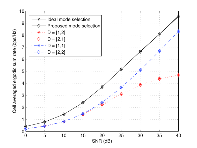
Next, Figure 3 presents the simulation results employing the proposed transmission selection scheme with random user locations. Users are randomly generated with a uniform distribution within a cell and the number of user generations is set to . Figure 3 evaluates the cell averaged ergodic sum rate performance of the proposed transmission selection scheme with . To confirm the performance of our proposed scheme, we also plot the ergodic sum rate performance of the ideal mode selection where the sum rates are calculated by averaging actual channel realizations for all possible transmission modes. We can notice that the performance of our proposed scheme based on the minimum distance is identical to that of the ideal mode selection. The sum rate performance with each mode is also presented. Here, and , and and exhibit the same performance, respectively, because the sum rates for all user positions are averaged in a cell. The two user transmission modes () show no difference in the averaged sum rate compared with the single user transmission modes () for low SNR, but the saturated performance is observed at high SNR. This is due to a fact that the other users’ interference power degrades the sum rate performance severely for high SNR where interference becomes a dominant factor. It is obvious from the plot that the proposed mode selection scheme exploits a selection gain over fixed transmission modes.
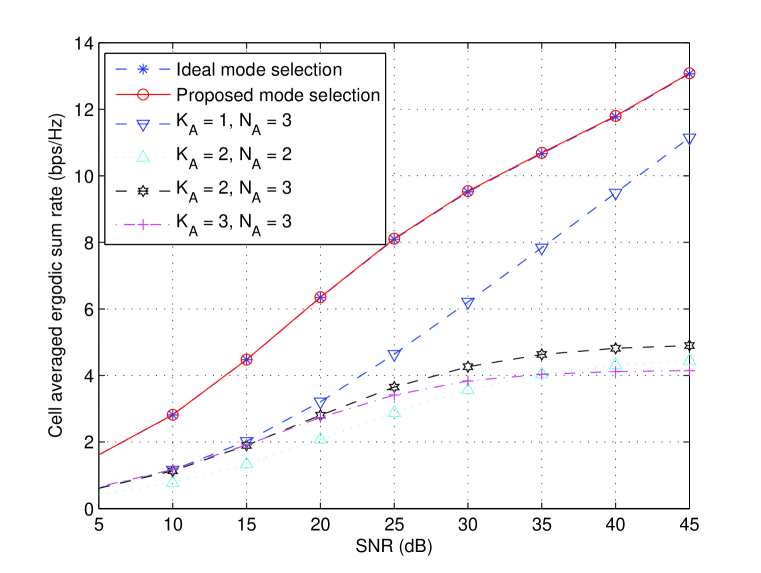
Figure 4 presents the cell averaged ergodic sum rate performance in the DAS with . Although the proposed scheme chooses the best mode with reduced mode candidates, the obtained ergodic sum rate performance is the same as the ideal mode selection. In this figure, similar to Figure 3, the cell averaged ergodic sum rate performance of the single user transmission modes approaches that of the ideal mode selection in high SNR region, since single user transmission outperforms multi-user transmission in interference limited environments.
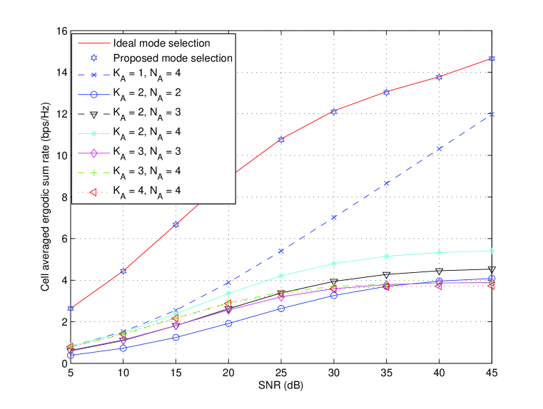
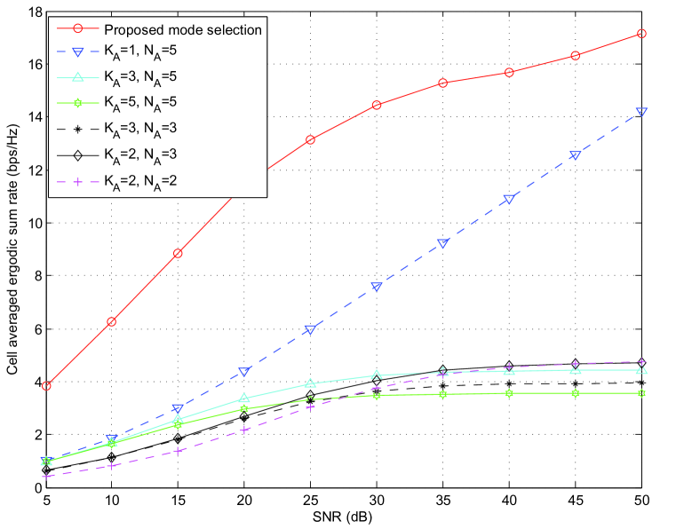
In Figure 5, we plot the performance of the DAS with . Similar to the previous cases, in high SNR region, the single user transmission modes exhibit the best sum rate compared to other modes, while the curves for the multi-user transmission modes are flattened. Here, the performance of modes for the multi-user case is saturated with a higher ergodic sum rate value as the number of active users decreases and the number of active DA ports increases. It should be emphasized again that our proposed scheme based on the minimum distance reduces the number of mode candidates substantially without any performance loss compared to the ideal mode selection. The number of mode candidates for the ideal mode selection is for , while the proposed scheme requires only mode candidates. It is clear that savings on the candidate set size reduction becomes significant as the number of users and DA ports increases.
Figure 6 presents the average ergodic sum rate for DAS with . In this case, the results for the ideal mode selection are not included, since the number of candidates is and the simulations for this case become prohibitive. In this plot, we observe similar trends as before. By comparing Figures 4, 5, and 6, we can see that an ergodic sum rate gain obtained by the proposed mode selection method grows as and become large compared to the individual fixed transmission modes. In addition, a transmission mode selection gain decreases as the SNR becomes large.
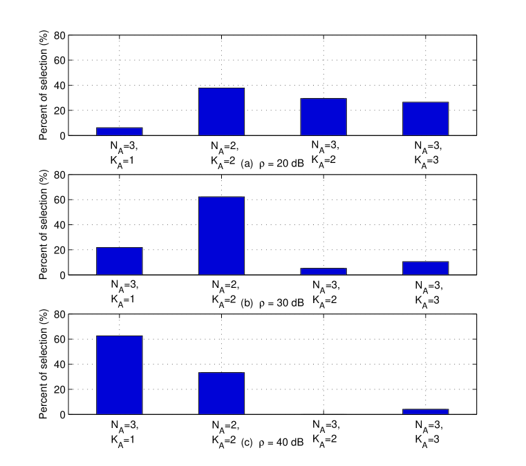
In Figure 7, we plot the histogram of the selected transmission modes in various SNR ranges and categorize the transmission modes into groups according to and for DAS with . From Figure 7, it is obvious that the single user transmission modes are mostly selected as the best mode as the SNR increases in DAS. Thus, it is expected that a gain obtained by the proposed mode selection is reduced at high SNR region over the performance of modes with and , which have the best sum rate performance among all modes. This can also be seen as a reason why the sum rate performance of single users transmission modes approaches that with mode selection as shown in Figures 3 6.
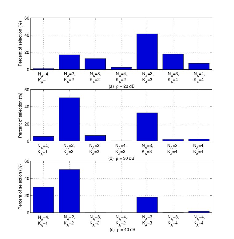
Similarly, we illustrate the histogram of selected modes for the DAS with in Figure 8. Compared to the DAS with in Figure 7, the probability that the single user transmission modes are selected is reduced for . Therefore, although single user transmission modes show better sum rate performance than multi-user transmission modes, a gain obtained by applying the mode selection method over the modes with is expected to grow with high probability as and increase. We can observe this characteristics in Figures 3, 4 and 5. In addition, since interference becomes a dominant factor for sum rate performance as the SNR increases, multi-user modes with fewer active DA ports are preferred as shown in Figures 7 and 8.
VII Conclusions
In this paper, we have studied the multi-user multi-DA port downlink DAS and have derived an ergodic sum rate expression using the pdf of users’ SINR. Based on the derived expressions, we have proposed a transmission selection scheme to maximize the ergodic sum rate. In the proposed scheme, mode candidates are generated by considering pairings of each active DA port and the nearest user. Then, we select the mode which maximizes the ergodic sum rate.
The number of mode candidates is reduced dramatically without any performance loss by applying the proposed scheme. Also, we have analyzed the SNR cross-over points for different transmission modes. The effectiveness of the proposed scheme has been confirmed through simulations. We have verified the sum rate performance of the proposed scheme for various configurations.
References
- [1] G. J. Foschini and M. Gans, “On Limits of Wireless Communications in a Fading Environment when Using Multiple Antennas,” Wireless Personal Communications, vol. 6, pp. 311–335, March 1998.
- [2] H. Lee, B. Lee, and I. Lee, “Iterative Detection and Decoding with an Improved V-BLAST for MIMO-OFDM Systems,” IEEE Journal on Selected Areas in Communications, vol. 24, pp. 504–513, March 2006.
- [3] H. Lee and I. Lee, “New Approach for Error Compensation in Coded V-BLAST OFDM Systems,” IEEE Transactions on Communications, vol. 55, pp. 345–355, February 2007.
- [4] I. Lee, A. M. Chan, and C.-E. W. Sundberg, “Space-Time Bit-Interleaved Coded Modulation for OFDM Systems,” IEEE Transactions on Signal Processing, vol. 52, pp. 820–825, March 2004.
- [5] W. Choi and J. G. Andrews, “Downlink Performance and Capacity of Disributed Antenna Systems in a Multicell Environment,” IEEE Transactions on Wireless Communications, vol. 6, pp. 69–73, January 2007.
- [6] X. Wang, P. Zhu, and M. Chen, “Antenna Location Design for Generalized Distributed Antenna Systems,” IEEE Communications Letters, vol. 13, pp. 315 – 317, May 2009.
- [7] E. Park and I. Lee, “Antenna Placement for Downlink Distributed Antenna Systems with Selection Transmission,” in Proc. IEEE VTC ’11, vol. 1, pp. 1–5, May 2011.
- [8] M. V. Clark, T. M. Willis, L. J. Greenstein, A. J. Rustako, V. Ercegt, and R. S. Roman, “Distributed versus Centralized Antenna Arrays in Broadband Wireless Networks,” in Proc. IEEE VTC ’01, vol. 1, pp. 33–37, May 2001.
- [9] L. Dai, S. Zhou, and Y. Yao, “Capacity analysis in CDMA distributed antenna systems,” IEEE Transactions on Wireless Communications, vol. 4, pp. 2613–2620, November 2006.
- [10] W. Roh and A. Paulraj, “Outage Performance of the Distributed Antenna Systems in a Composite Fading Channel,” in Proc. IEEE VTC ’02, vol. 3, pp. 1520–1524, September 2002.
- [11] R. Hasegawa, M. Shirakabe, R. Esmailzadeh, and M. Nakagawa, “Downlink Performance of a CDMA System with Distributed Base Station,” in Proc. IEEE VTC ’03, vol. 2, pp. 882–886, October 2003.
- [12] L. Xiao, L. Dai, H. Zhuang, S. Zhou, and Y. Yao, “Information-Theoretic Capacity Analysis in MIMO Distributed Antenna Systems,” in Proc. IEEE VTC ’03, vol. 1, pp. 779–782, April 2003.
- [13] W. Feng, X. Xu, S. Zhou, J. Wang, and M. Xia, “Sum Rate Characterization of Distributed Antenna Systems with Circular Antenna Layout,” in Proc. IEEE VTC ’09, vol. 1, pp. 1–5, April 2009.
- [14] W. Feng, X. Zhang, S. Zhou, J. Wang, and M. Xia, “Downlink Power Allocation for Distributed Antenna Systems with Random Antenna Layout,” in Proc. IEEE VTC ’09, vol. 1, pp. 1–5, September 2009.
- [15] H. Hu, M. Weckerle, and J. Luo, “Adaptive Transmission Mode Selection Scheme for Distributed Wireless Communication Systems,” IEEE Communications Letters, vol. 10, pp. 573 – 575, July 2006.
- [16] J. Gan, Y. Li, S. Zhou, and J. Wang, “Adaptive Transmit-Receive Mode Selection for Multi-User Distributed Wireless Communication System,” in Proc. IEEE WCNC ’07, vol. 1, pp. 1–5, March 2007.
- [17] WiMAX Forum, Mobile WiMAX - Part I: A Technical Overview and Performance Evaluation, August 2006.
- [18] A. Gjendemsjo, D. Gesbert, G. E. Oien, and S. G. Kiani, “Binary Power Control for Sum Rate Maximization over Multiple Interfering Links,” IEEE Transactions on Wireless Communications, vol. 7, pp. 3164–3173, August 2008.
- [19] A. Jeffrey and D. Zwillinger, Table of Integrals, Series, and Products. seventh Edition, Academic Press, 2007.
- [20] A. Milton and I. Stegun, Handbook of Mathematical Functions with Formulas, Graphs, and Mathematical Tables. Dover Publications, 1965.

| Set as the mode where each DA port serves its nearest user with |
| Generate an -digit binary number where each bit represents on/off for the |
| corresponding DA port. |
| end |
| Add if the number of non-zero elements |
| end |
| . |
| Add |