Landau-Zener-Stuckelberg interferometry of a single electron spin in a noisy environment
Abstract
We demonstrate quantum coherent control of a single electron spin in a NV center in diamond using the Landau-Zener-Stuckelberg interferometry at room temperature. Interference pattern is observed oscillating as a function of microwave frequency. The decays in the visibility of the interference are well explained by numerical simulation which includes the thermal fluctuations of the nuclear bath which shows that Landau-Zener-Stuckelberg interferometry can be used for probing electron spin decoherence processes.
pacs:
03.67.Ac, 42.50.DvLandau-Zener(LZ) tunneling is a well-known phenomenon associated with strong-driving. When a two-level system is driven through the avoided level crossing, LZ tunneling can be controlled to create various superposition of the energy eigenstates, like a coherent beam splitter. Combining two consecutive LZ tunneling leads to Landau-Zener-Stuckelberg(LZS) quantum interference which is analogous to the Mach-Zehnder(MZ) interferometry. LZS interference has been observed in Rydeberg atoms1Rydberg atoms ; 2Rydberg atoms , quantum dots contacts3QPC , and recently in mesoscopic superconducting Josephson devicesSCJ ; CPB , ultracold molecularultracold and Optical Latticesoptic . LZ tunneling and LZS interference have also been exploited for quantum states preparation7 ; 8 and manipulation9 ; 10 . Interaction with the environment disturbs the coherence of the quantum system and therefore manifests in the LZS interference patterndec1 ; dec2 . LZS interferometry thus provides crucial information on the decoherence processes by the environments.
Single electron spins of nitrogen-vacancy centre(NV centre)has been one of the most popular candidate as a qubit carrier. The high controllability as well as a favorable coherence time promises room temperature quantum information processingcoherence1 ; entangle ; read1 ; coherence2 and high sensitive magnetometrymag1 ; mag2 ; mag3 . High efficiency initialization of NV center spin on desired pure state can be done via optical pumping. Quantum coherent controls of individual spin can be realized using the conventional microwave pulsed controls. NV center is also an ideal platform for studying quantum phenomena, especially, the processes in a strong-driving regime such as anharmonic dynamicsGigahertz and the multifrequency spectramulti .
In this letter, we carried out LZS interferometry on a NV centre in high purity diamond and demonstrated the feasibility of using LZS for quantum coherent control of single electron spin. In this experiment, we first realize a coherent beam splitter for electron spin states based on the LZ tunneling process, this is realized in and then, by repeating such process twice under different microwave frequency, quantum interference known as Stuckelberg oscillation is observed. The decays in the interference fringes agrees well with numerical simulations taking into account the hyperfine coupling of the electron spin with the surrounding nuclear spin bath. Our study shows that the thermal fluctuations of the nuclear spins is the dominate cause of observed coherence lose at room temperature.
LZ tunneling was first studied by Landau and ZenerOri1 ; Ori2 and a description of the variety of phenomenon related to LZ tunneling and LZS interference can be found in a recent review26 . The problem rely on a two-level system, described by the LZ Hamiltonian,
| (1) |
which contains a minimum energy separation (the avoided level crossing), a time dependent driving field and a offset . To implement LZ tunneling, the system is prepared in an eigenstate of , denoted by , while the driving field is set to be much larger than . In this way the initial state is close to one of the eigenstates of . Next, is gradually tuned down, and as the system is swept through the avoided level crossing where , undergoes LZ tunneling and is split into a superposition of and . The probability of remaining in is given by the well-known LZ formula:
| (2) |
where and is the sweep velocity which equals to the value of at the avoided crossing. The LZS interferometer can also be conceived as a MZ interferometer, as shown in Fig. 1(b). Starting with , the system undergoes LZ tunneling at where the superposition of the and is generated. The system subsequently evolves and accumulates a relative phase . When is swept back to the avoided level crossing at , and interfere. The relative phase is given by
| (3) |
with the energy difference between and . It is that gives rise to the interference fringes in the occupation probability known as Stuckelberg oscillations.
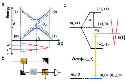
The key issue in LZ tunneling is the realization of an avoided level crossing in energy states. Nevertheless, due to the large crystal splitting of the NV center, such a scheme cannot be implemented directly by electron spin resonance where a formidable strength of microwave field is required. In our scheme, the avoided level crossing is realized in the rotating frame where a microwave field can act as the minimum energy separation, similar method has been used in solid state electron spins Gigahertz ; multi as well as in superconducting Josephson devicesYu . We consider the NV center system which includes a spin-one electron spin and a nearby nuclear spin. The Hamiltonian can be written as
| (4) |
Here GHz is the crystal field splitting and is the external magnetic field applied along the axis ([111] crystal axis) which lifts the degeneracy of electron spin states and . is the Bohr magneton and the electron -factor. The third term of Eq. (4) is the hyperfine coupling between the electron spin and the nuclear spin (MHz), which contributes an effective field to the center spin conditioned on the state (we neglect the dynamics of for simplicity.) To realize the corresponding avoided level crossing in such a system, we first transform to the subspace spanned by and as in Fig. 1(c), which will be denoted by and in the following. Applying a microwave field along the axis selectively excites the transition when . In the rotating frame of , acts as a static field along the axis. Finally, by assuming a time dependent field along the axis with amplitude smaller than , the dynamics of and in the rotating frame can be expressed by . By tuning the strength of the microwave field, one can change the minimum energy separation , while by tuning the microwave frequency, can be controlled.
We describe the experimental set-up for the demonstration of the LZS interferometry. The experiment is carried out on a home-built confocal microscope operated at room temperature. The sample is type IIa single crystal diamond with abundance of nitrogen electron spins less than 5ppb. A single NV is addressed via a microscope mounted on a piezoscanner by its fluorescence signals. A Hanbury-Brown-Twiss setup with two photodetectors is used to ensure the single NV (data not shown). A 532nm laser is used to initialize and read out the system. To manipulate the electron spin coherently, a microwave signal is first generated by a ratio signal generator, then a linear amplifier is employed to enhance the microwave power output. Finally, a 20m diameter copper wire terminated by a Ohm resistance is used to radiate the microwave field to the NV center. The degeneracy between and is lifted by an external magnetic field generated by three pairs of Helmholtz coils, with resolution Gauss. In the experiment a magnetic field of 5 Gauss is employed. The driving field in is generated by an Arbitrary Waveform Generator(AWG) and the signal is directly sent to the sample via the copper wire. In the experiment, the typical frequency of the driving field is several kHz which is much smaller than the microwave frequency, thus only the components along the axis contribute. All signals are synchronized by a pulse generator. To build up statistic, we use typically cycles in a single measurement. is calculated using the output power of the amplifier and the amplitude of the driving field from the output voltage of the AWG. Typically, kHz at 20dBm output while 4V (peak-to-peak value of sine wave) in AWG corresponds to a driving field amplitude of 1.4MHz.
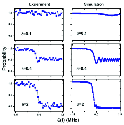
Next, we describe the demonstration of the LZS interferometer. As preparation, we first accomplished LZ tunneling that can act as a beam splitter for electron spin states. Fig. 2 shows the measured and simulated LZ tunneling dynamics under a driving field cos for different values of the adiabaticity parameter . The simulation is based on and the environment is not taken into account. By tunning the adiabaticity parameter, the tunneling probability can be controlled. Such a beam splitter can be further exploited to construct the LZS interferometer. According to the classical LZS interference theory26 , beginning in , the probability of the system keeping in the same state after undergoing two consecutive LZ tunneling is given by
| (5) |
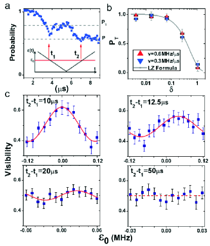
Here is the LZ tunneling rate, and with coming from Stokes phase. Fig. 3(a) shows the characteristic dynamics of the LZS interference process, while as a function of sweeping velocity is plotted in Fig. 3(b). To extract out the quantum coherence term in (4), we defined the interference visibility as . Without noises, is expected oscillating between 0 and 1 as a function of . However, as shown by the observed Stuckelberg oscillation(Fig. 3(b)), the visibility of interference fringes decrease as increasing the duration of the interference process. Such an effect clearly indicates a loss of quantum coherence between and .
To understand the observed decay in the interference pattern, the environment must be taken into account. In high purity single crystals, where the abundance of nitrogen electron spins is less than 5ppb, the main source of decoherence comes from the dipolar interaction with the nuclear spins decoherence . This interaction, together with the dynamics of the nuclear spin bath can be expressed by in the subspace of the LZS interferometer. Here is the coupling to the nuclear spin bath, which can be written as , with the coupling coefficient for the th nuclear spin (the coupling strength is of the order of kHz). The fluctuation perpendicular is negligible since it is too weak to cause the spin-flip relaxation. contains the dynamics of the bath, which includes the Zeeman splitting (several kHz) of the nuclear spins in the external magnetic field and the dipolar interaction between nuclear spins (of the order of Hz). During the interference process, which occurs within tens of microsecond, the dynamics of the bath are negligible. We therefore expect that only the statistical fluctuations arising from the random orientations of the nuclear spins at room temperature contribute to the interference process. These fluctuations follow a Gaussian distribution NVdec1 , where can be directly extracted from the FID measurement (Fig. 4(b)). It is found that kHz for the NV center under study.
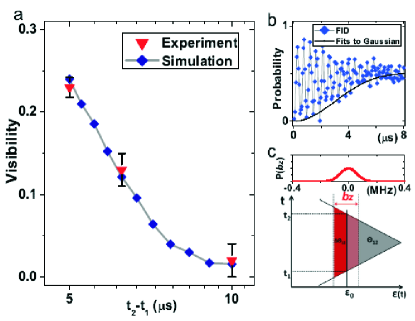
Based on these considerations, numerical simulations were performed, with the measured and simulated results shown in Fig. 4(a). Good agreement between experiment and theory clearly establishes the decay mechanism as being due to nuclear spins. One also can capture the essence of the observations through the intuitive picture presented in Fig. 4(c). The phase giving rise to the interference fringes comes from the energy accumulated between two LZ tunneling points and is proportional to the duration of interference process multiplied by the amplitude of the driving field. The presence of the effective field can change the position of the avoided level crossing and therefore cause fluctuations in . As a result, the oscillations are washed out and the visibility decreases. This effect becomes more serious as the duration of the total process increases.
In conclusion, we have demonstrated a beam splitter of spin states of the NV centre at room temperature based on LZ tunneling, Our results showed that the tunneling probability is only given by the adiabaticity parameter which agrees with the original prediction of LZ formula. Combining two such beam splitters, LZS interferometer is realized and the Stuckelberg oscillation is observed, the decays in visibility of the interference fringes at room temperature is caused by thermal fluctuation of nuclear spins and agrees well with numerical simulations. Our work establishes the feasibility of using LZS interferometry for quantum coherent control and for probing decoherence processes of single spin in NV center.
We thank W. Yao and D. Culcer for helpful discussion and reading the paper. This work was supported by the National Natural Science Foundation of China (Grant No. 91021005), the CAS, and the National Fundamental Research Program (Grant No. 2007CB925200).
References
- (1) S. Yoakum et al., Phys. Rev. Lett. 69, 1919 (1992).
- (2) Baruch,M.C and T.F.Gallagher, Phys. Rev. Lett. 68, 3515 (1992).
- (3) Gorelik L.Y. et al., Phys. Rev. Lett. 81, 2538 (1998).
- (4) W. D. Oliver et al, Science 310, 1653 (2005).
- (5) S. Sillanpaa et al., Phys. Rev. Lett. 96, 187002 (2006).
- (6) M. Mark et al., Phys. Rev. Lett. 99, 113201 (2007).
- (7) S. Kling et al., Phys. Rev. Lett. 105, 215301 (2010)
- (8) D. J. Reilly et al., Science 321, 817 (2008).
- (9) H. Ribeiro et al., Phys. Rev. Lett. 102, 216802 (2009).
- (10) J. R. Petta et al., Science 327, 669 (2010).
- (11) Guozhu Sun et al., Nature communications 1(5), 51 (2010).
- (12) D. M. Berns et al., Phys. Rev. Lett. 97, 150502 (2006).
- (13) M. S. Rudner et al., Phys. Rev. Lett. 101, 190502 (2008).
- (14) M. V. Gurudev Dutt et al. Science 316, 1312 (2007).
- (15) P. Neumann et al., Science 320, 1326 (2008).
- (16) P. Neumann et al., Science 329, 542 (2010).
- (17) G. Balasubramanian et al., Nat. Mater. 8, 383 (2009).
- (18) J. R. Maze et al., Nature 455, 644 (2008).
- (19) G. Balasubramanian et al., Nature (London) 455, 648 (2008).
- (20) G. de Lange et al., Phys. Rev. Lett. 106, 080802(2011).
- (21) G. D. Fuchs et al., Science 326, 1520(2009).
- (22) L. Childress et al., Phys.Rev.A 82, 033839(2010).
- (23) Landau,L.D., Phys.Z 2, 46(1932).
- (24) Zener,C, Proc.R.Soc.London A 137, 696(1932).
- (25) S. Shevchenko, S. Ashhab, and F. Nori, Phys. Rep. 492, 1 (2010).
- (26) G. Sun et al., arXiv:1010.5897 .
- (27) L. Childress et al., Science 314, 281(2006).
- (28) R. Hanson et al., Science 320, 352(2008).