-titleFusion11 11institutetext: Department of Physics and Astronomy, Vanderbilt University, Nashville, Tennessee 37235, USA 22institutetext: Institut für Theoretische Physik, Goethe-Universität, D-60438 Frankfurt am Main, Germany 33institutetext: Institut für Theoretische Physik, Universität Erlangen, D-91054 Erlangen, Germany
Microscopic Calculation of Heavy-Ion Potentials Based on TDHF
Abstract
We discuss the implementation and results of a recently developed microscopic method for calculating ion-ion interaction potentials and fusion cross-sections. The method uses the TDHF evolution to obtain the instantaneous many-body collective state using a density constraint. The ion-ion potential as well as the coordinate dependent mass are calculated from these states. The method fully accounts for the dynamical processes present in the TDHF time-evolution and provides a parameter-free way of calculating fusion cross-sections.
1 Introduction
The study of internuclear potentials for heavy-ion collisions is of fundamental importance for calculating fusion cross-sections, and for studying the formation of superheavy elements and nuclei far from stability. While asymptotically such potentials are determined from Coulomb and centrifugal interactions, the short distance behavior strongly depends on the nuclear surface properties and the readjustments of the combined nuclear system, resulting in potential pockets, which determine the characteristics of the compound nuclear system.
Among the various approaches for calculating ion-ion potentials are: 1) Phenomenological models such as the Bass model Ba80 , the proximity potential BR77 , and potentials obtained via the double-folding method SL79 ; RO83a . Some of these potentials have been fitted to experimental fusion barrier heights and have been remarkably successful in describing scattering data. 2) Semi-microscopic and full microscopic calculations such as the macroscopic - microscopic method KN79 ; II05 , the asymmetric two-center shell-model MG72 , constrained Hartree-Fock (CHF) with a constraint on the quadrupole moment or some other definition of the internuclear distance ZM76 ; BB04 , and other mean-field based calculations DN02 ; DP03 ; GB05 .
One common physical assumption used in many of the semi-microscopic calculations is the use of the frozen density or the sudden approximation. As the name suggests, in this approximation the nuclear densities are unchanged during the computation of the ion-ion potential as a function of the internuclear distance. On the other hand, the microscopic calculations follow a minimum energy path and allow for the rearrangement of the nuclear densities as the relevant collective parameter changes. In this paper, we shall call this the static adiabatic approximation since a real adiabatic calculation would involve a fully dynamical calculation, thus also including the effects of dynamical rearrangements.
Recently, we have developed a new method to extract ion-ion interaction potentials directly from the TDHF time-evolution of the nuclear system. In the DC-TDHF approach UO06b the TDHF time-evolution takes place with no restrictions. At certain times during the evolution the instantaneous density is used to perform a static Hartree-Fock minimization while holding the neutron and proton densities constrained to be the corresponding instantaneous TDHF densities. In essence, this provides us with the TDHF dynamical path in relation to the multi-dimensional static energy surface of the combined nuclear system. In this approach there is no need to introduce constraining operators which assume that the collective motion is confined to the constrained phase space. In short, we have a self-organizing system which selects its evolutionary path by itself following the microscopic dynamics. Some of the effects naturally included in the DC-TDHF calculations are: neck formation, mass exchange, internal excitations, deformation effects to all order, as well as the effect of nuclear alignment for deformed systems.
2 DC-TDHF Method
2.1 Formalism
The concept of using density as a constraint for calculating collective states from TDHF time-evolution was first introduced in Ref. CR85 , and used in calculating collective energy surfaces in connection with nuclear molecular resonances in Ref. US85 .
In this approach we assume that a collective state is characterized only by density , and current . This state can be constructed by solving the static Hartree-Fock equations
| (1) |
subject to constraints on density and current
Choosing and to be the instantaneous TDHF density and current results in the lowest energy collective state corresponding to the instantaneous TDHF state , with the corresponding energy
| (2) |
This collective energy differs from the conserved TDHF energy only by the amount of internal excitation present in the TDHF state, namely
| (3) |
However, in practical calculations the constraint on the current is difficult to implement but we can define instead a static adiabatic collective state subject to the constraints
In terms of this state one can write the collective energy as
| (4) |
where the density-constrained energy , and the collective kinetic energy are defined as
From Eq. 4 is is clear that the density-constrained energy plays the role of a collective potential. In fact this is exactly the case except for the fact that it contains the binding energies of the two colliding nuclei. One can thus define the ion-ion potential as
| (5) |
where and are the binding energies of two nuclei obtained from a static Hartree-Fock calculation with the same effective interaction. For describing a collision of two nuclei one can label the above potential with ion-ion separation distance obtained during the TDHF time-evolution. This ion-ion potential is asymptotically correct since at large initial separations it exactly reproduces . In addition to the ion-ion potential it is also possible to obtain coordinate dependent mass parameters. One can compute the “effective mass” using the conservation of energy
| (6) |
where the collective velocity is directly obtained from the TDHF evolution and the potential from the density constraint calculations.
2.2 Calculation of
In practice, TDHF runs are initialized with energies above the Coulomb barrier at some large but finite separation. The two ions are boosted with velocities obtained by assuming that the two nuclei arrive at this initial separation on a Coulomb trajectory. Initially the nuclei are placed such that the center of mass is located at , and the plane represents the collision plane. During the TDHF dynamics the ion-ion separation distance is obtained by constructing a dividing plane between the two centers and calculating the center of the densities on the left and right halves of this dividing plane. The coordinate is the difference between the two centers. The dividing plane is determined by finding the point at which the tails of the two densities intersect each other along the -axis. However, this procedure starts to fail after a substantial overlap is reached. Instead, one can define the ion-ion separation as , where is the mass quadrupole moment for the entire system, calculated by diagonalizing the quadrupole tensor to obtain the quadrupole moment along the principal axis, and is a scale factor determined to give the correct initial separation distance at the start of the calculations. Calculating this way yields numerically identical results to the previous procedure until that procedure begins to fail and continues smoothly after that point.
2.3 Fusion cross-section
We now outline the calculation of the total fusion cross section using a coordinate-dependent mass and potential . Starting from the quantized Hamiltonian
| (7) |
with the momentum operator , the total fusion cross cross-section
| (8) |
can be obtained by calculating the potential barrier penetrabilities from the Schrödinger equation for the relative motion coordinate using the Hamiltonian (7) with an additional centrifugal potential
| (9) |
Alternatively, instead of solving the Schrödinger equation with coordinate dependent mass parameter for the heavy-ion potential , we can instead use the constant reduced mass and transfer the coordinate-dependence of the mass to a scaled potential using the well known coordinate scale transformation.
| (10) |
Integration of Eq. (10) yields
| (11) |
As a result of this point transformation, both the classical Hamilton function and the corresponding quantum mechanical Hamiltonian, Eq. (7), now assume the form
| (12) |
and the scaled heavy-ion potential is given by the expression
| (13) |
The fusion barrier penetrabilities are obtained by numerical integration of the two-body Schrödinger equation using the incoming wave boundary condition (IWBC) method. IWBC assumes that once the minimum of the potential is reached fusion will occur. In practice, the Schrödinger equation is integrated from the potential minimum, , where only an incoming wave is assumed, to a large asymptotic distance, where it is matched to incoming and outgoing Coulomb wavefunctions. The barrier penetration factor, is the ratio of the incoming flux at to the incoming Coulomb flux at large distance. Here, we implement the IWBC method exactly as it is formulated for the coupled-channel code CCFULL described in Ref. HR99 . This gives us a consistent way for calculating cross-sections at above and below the barrier energies.
2.4 Fusion with alignment
In the case of one or both of the reaction partners being deformed one has to incorporate the nuclear alignment into the evolution of the heavy-ion collision dynamics. This is done in two steps UO06c : a) A dynamical Coulomb alignment calculation to determine the probability that a given nuclear orientation occurs at the distance , where the TDHF run is initialized. The alignment generally results from multiple E2/E4 Coulomb excitation of the ground state rotational band. The distance is chosen such that the nuclei only interact via the Coulomb interaction. b) A TDHF calculation, starting at this finite internuclear distance , for a fixed initial orientation of the deformed nucleus. Since the experiments are usually done with unpolarized beams, in a full quantum mechanical calculation one would have to average over discrete quantum mechanical rotational bands. In the classical limit, this corresponds to averaging over orientation angles. In the case of one spherical nucleus and one deformed reaction partner, the total fusion cross section is given by an integral over all orientation (Euler) angles, with solid angle element
| (14) |
where represents the alignment probability and is the fusion cross section associated with a particular alignment calculated using the ion-ion potential, , obtained from the TDHF collision for which the deformed partner is initialized with angle with respect to the collision axis. Details for the most general case is given in Refs. UO06c ; UO08a .
3 Application
In this section we will give selected examples of the DC-TDHF method for calculating fusion cross-sections. Calculations were done in a 3-D Cartesian box large enough to avoid any initialization or box boundary effects. We have used the full Skyrme force (SLy4) CB98 . The numerical accuracy of the static binding energies and the deviation from the point Coulomb energy in the initial state of the collision dynamics is on the order of keV. We have performed density constraint calculations at every fm/c interval. The accuracy of the density constraint calculations are commensurate with the accuracy of the static calculations.
3.1 Spherical system
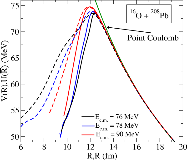
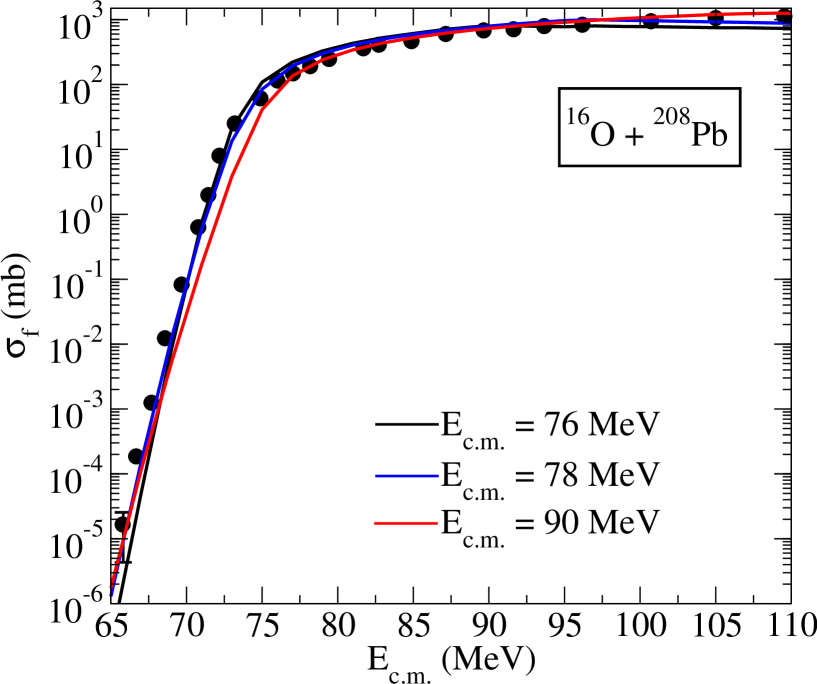
The DC-TDHF method is expected to do best for nuclei that are well described by the Skyrme HF calculations. One such reaction is the fusion of 16O+208Pb system. In Fig. 1 we show an example of microscopic potentials for the 16O+208Pb system at three difference center-of-mass energies UO09a . The dashed curves are the corresponding potentials transformed via the microscopically calculated effective mass, . We observe that all of the scaled barriers give a very good description of the fusion cross-section at higher energies suggesting these cross-sections are primarily determined by the barrier properties in the vicinity of the barrier peak, whereas for the extreme sub-barrier cross-sections are influenced by what happens in the inner part of the barrier and here the dynamics and consequently the coordinate dependent mass becomes very important (see Fig. 2). Specifically, we can see from Fig. 1 that as the c.m. energy is increased the ion-ion potential peak increases but the inner part of the barrier becomes narrower. This is due to the fact that for high energies the system does not have enough time for rearrangements in the density to occur and the barrier approaches the frozen-density limit. However, at lower energies substantial density rearrangements occur which modifies the inner part of the barrier. This modification is important for fusion cross-sections are deep sub-barrier energies.
3.2 Deformed systems
The collision of the 64Ni+132Sn system represents a good example of a collision involving a deformed (oblate) nucleus, 64Ni and a neutron rich nucleus. Fusion cross-sections for this system have been experimentally measured Li07 and initially a significant discrepancy was observed with standard coupled-channel calculations. We have used the DC-TDHF method to study this system UO06d ; UO07a . The ion-ion potentials corresponding to two extreme orientations of the 64Ni nucleus are shown in Fig. 3 as well as an empirical barrier used in barrier penetration calculations in Ref. Li07 . Two important points are observed from this plot. The first is the strong dependence of the barrier height and location on the alignment of the deformed nucleus. We also see that the empirical barrier is very close to the equatorial orientation, which is closer to the assumption of spherical nuclei. The accuracy of our result with no parameters or normalization is impressive. The second point has to do with the meaning of sub-barrier; as seen from Fig. 3, while the experimental energies appear to be all sub-barrier with respect to the spherical barrier, two of them are above the barrier with respect to the potential barrier and the third faces a considerably narrower barrier. This explains the anomalous observation of enhanced fusion at these energies.
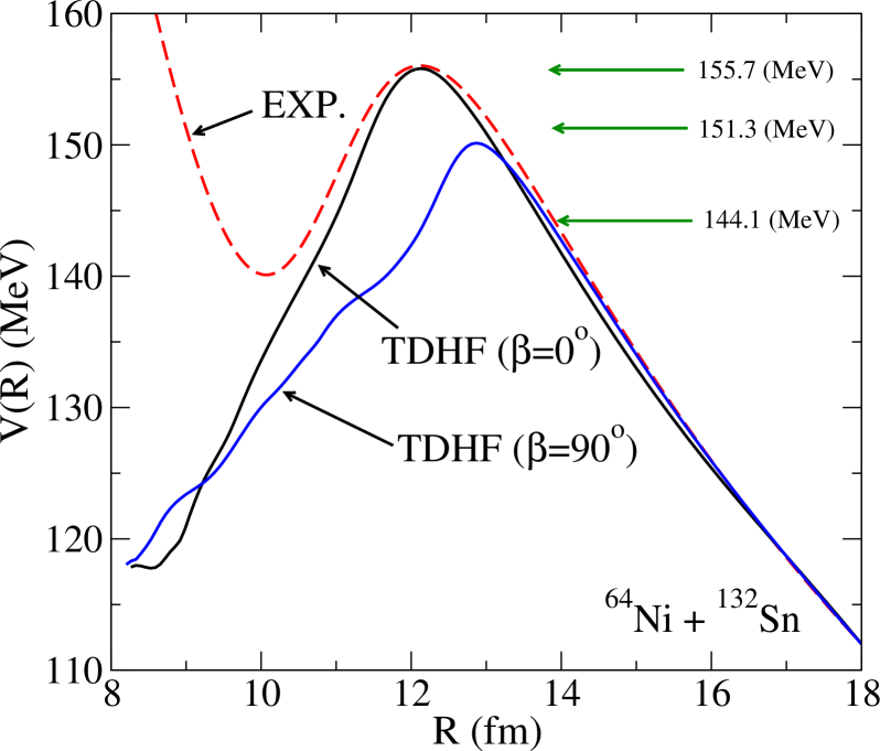
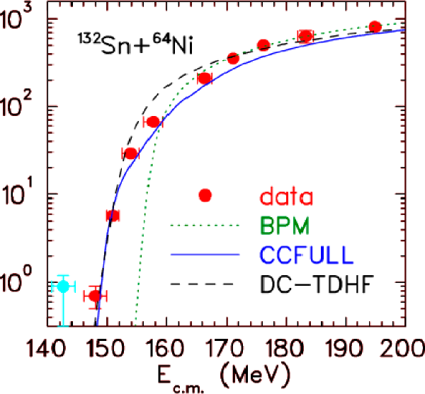
Fig. 4 shows the experimental and theoretical fusion cross-sections calculated with different methods. The coupled-channel calculations are modified to include multiple neutron transfer. As we see again the DC-TDHF results reproduce the fusion cross-sections reasonably well.
3.3 Superheavy systems
Ion-ion interaction potentials calculated using DC-TDHF correspond to the configuration attained during a particular TDHF collision. For light and medium mass systems as well as heavier systems for which fusion is the dominant reaction product, DC-TDHF gives the fusion barrier with an appreciable but relatively small energy dependence. On the other hand, for reactions leading to superheavy systems fusion is not the dominant channel at barrier top energies. Instead the system sticks in some dinuclear configuration with possible break-up after exchanging a few nucleons. For this reason the energy dependence of the DC-TDHF interaction barriers for these systems is not just due to the dynamical effects for the same final configuration but actually represent different final configurations. For the same reasons calculations presented here can only address the capture cross-section for these systems since the long-time evolution to complete fusion or break-up is beyond the scope of TDHF due to the absence of quantum decay processes and transitions.
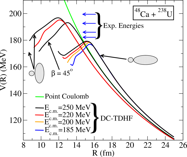
As an example of superheavy formation from a hot-fusion reaction we have studied the 48Ca+238U system UO10a . Hartree-Fock (HF) calculations produce a spherical 48Ca nucleus, whereas 238U has a large axial deformation. The large deformation of 238U is expected to strongly influence the interaction barriers for this system. This is shown in Fig. 5, which shows the interaction barriers, , calculated using the DC-TDHF method as a function of c.m. energy and for three different orientations of the 238U nucleus. The alignment angle is the angle between the symmetry axis of the 238U nucleus and the collision axis. Also shown in Fig. 5 is the point Coulomb potential corresponding to this collision. The deviations from the point Coulomb potential at large values are due to the deformation of the 238U nucleus. We first notice that the barriers corresponding to the polar orientation () of the 238U nucleus are much lower and peak at larger ion-ion separation distance . On the other hand, the barriers corresponding to the equatorial orientation of 238U () are much higher and peak at smaller values. For the intermediate values of the barriers rise rapidly as we increase the orientation angle from , as can be seen for . The rise in the barrier height as a function of increasing values is not linear but seems to rise more rapidly for smaller values. We also see that for lower energies central collisions with polar orientation of 238U are the only orientations which result in the sticking of the two nuclei, while the equatorial orientations of 238U result in a deep-inelastic collision. Also, shown in Fig. 5 are the experimental energies Og07 for this reaction. We observe that all of the experimental energies are above the barriers obtained for the polar alignment of the 238U nucleus.
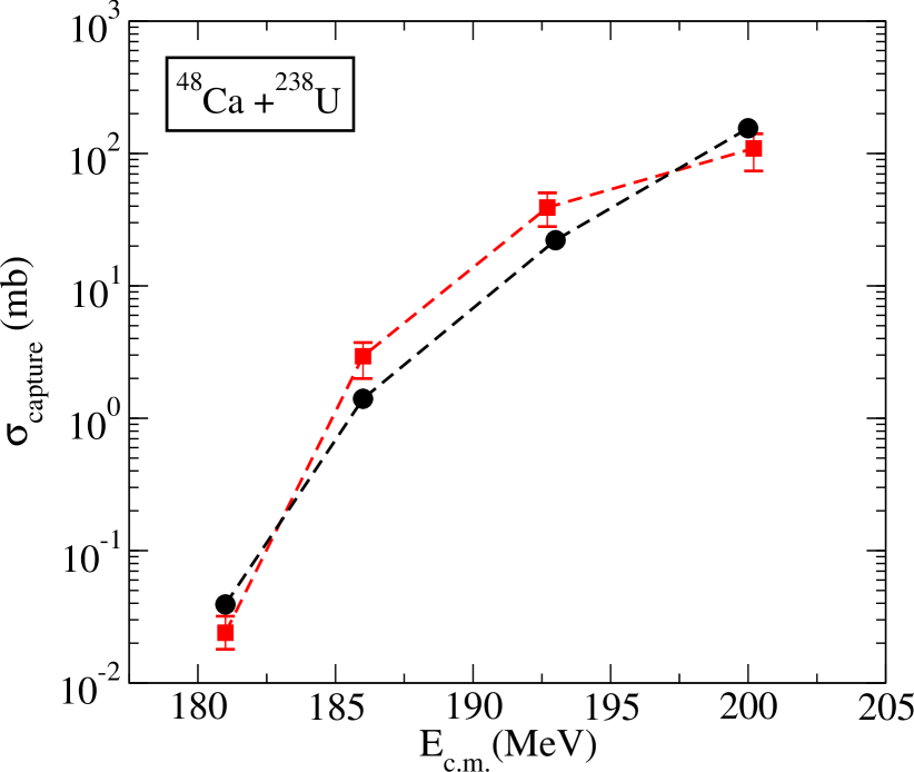
For the calculation of the capture cross-section we need to average over all possible alignments of the 238U nucleus as indicated by Eq. (14). Due to the relatively small charge of the 48Ca nucleus the alignment probability of Eq. (14) is in the range and does not vary appreciably with energy. In Fig. 6 we show the capture cross-sections for the 48Ca+238U system as a function of energy (black circles). Also, shown are the experimental cross-sections (red squares) Og07 . One important fact to notice in the cross-section formula given in Eq. (14) is that the cross-section is multiplied by the factor, which renders the contribution originating from the lowest barriers at small values of to be very small.
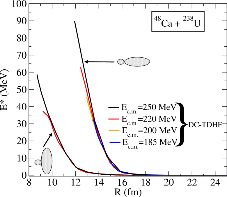
In Fig. 7 we also show the excitation energy as a function of c.m. energy and for two alignment angles ( and ) of the 238U nucleus. The excitation energy curves start at zero excitation when the two nuclei are far apart, which also provides a test for the numerical accuracy of the calculation. We note that the system is excited much earlier during the collision process for the polar alignment of the 238U nucleus and has a higher excitation than the corresponding collision for the equatorial orientation. Only two curves are shown for the equatorial collision since at lower energies we have deep-inelastic collisions for this alignment. We note that the highest point reached for these excitation curves is chosen to be the point where the nuclei almost come to a stop inside the barrier, which corresponds to a nearly zero collective kinetic energy. Since this is determined during the initial phase of the collision the dinuclear system is not in thermal equilibrium. However, the system essentially oscillates about this point. For energies for which the collision outcome is capture this would be the excitation energy at the capture point.
4 Conclusions
In summary, we have used the fully microscopic DC-TDHF method to obtain ion-ion interaction barriers for calculating fusion and capture cross-sections. The standard, parameter free approach of DC-TDHF yields potential barriers that can accurately reproduce the fusion cross-sections. The DC-TDHF approach has now been applied to study a number of systems with very promising results. This further elucidates the point that for the proper description of fusion cross-sections dynamical effects such as neck formation and mass transfer must be included to modify the inner part of the potential barrier. Also interesting are the implications of the energy dependent barriers. These findings underscore the fact that additional modifications needed for phenomenological methods to explain the fusion cross-sections may largely be due to the inadequacy of the approximations made in treating the nuclear dynamics.
This work has been supported by the U.S. Department of Energy under grant No. DE-FG02-96ER40963 with Vanderbilt University, and by the German BMBF under contract Nos. 06FY9086 and 06ER142D.
References
- (1) R. Bass, Nuclear Reactions with Heavy Ions, (Springer-Verlag, New York, 1980).
- (2) J. Blocki, J. Randrup, W. J. Swiatecki, and C. F. Tsang, Ann. Phys. (N.Y.) 105, 427 (1977).
- (3) G. R. Satchler and W. G. Love, Phys. Rep. 55, 183 (1979).
- (4) M. J. Rhoades-Brown and V. E. Oberacker, Phys. Rev. Lett. 50, 1435 (1983).
- (5) H. J. Krappe, J. R. Nix, and A. J. Sierk, Phys. Rev. C 20, 992 (1979).
- (6) T. Ichikawa, A. Iwamoto, P. Möller, and A. J. Sierk, Phys. Rev. C 71, 044608 (2005).
- (7) J. Maruhn and W. Greiner, Z. Phys. 251, 431 (1972).
- (8) P. G. Zint and U. Mosel, Phys. Rev. C 14, 1488 (1976).
- (9) T. Bürvenich, M. Bender, J. A. Maruhn, and P.-G. Reinhard, Phys. Rev. C 69, 014307 (2004).
- (10) V. Yu. Denisov and W. Nörenberg, Eur. Phys. J. A 15, 375 (2002).
- (11) A. Dobrowolski, K. Pomorski, and J. Bartel, Nuclear Physics A729, 713 (2003).
- (12) H. Goutte, J. F. Berger, P. Casoli, and D. Gogny, Phys. Rev. C 71, 024316 (2005).
- (13) A. S. Umar and V. E. Oberacker, Phys. Rev. C 74, 021601(R) (2006).
- (14) R. Y. Cusson, P. -G. Reinhard, M. R. Strayer, J. A. Maruhn, and W. Greiner, Z. Phys. A 320, 475 (1985).
- (15) A. S. Umar, M. R. Strayer, R. Y. Cusson, P. -G. Reinhard, and D. A. Bromley, Phys. Rev. C 32, 172 (1985).
- (16) K. Hagino, N. Rowley, and A. T. Kruppa, Comp. Phys. Comm. 123, 143 (1999).
- (17) A. S. Umar and V. E. Oberacker, Phys. Rev. C 74, 024606 (2006).
- (18) A. S. Umar and V. E. Oberacker, Phys. Rev. C 77, 064605 (2008).
- (19) E. Chabanat, P. Bonche, P. Haensel, J. Meyer and R. Schaeffer, Nucl. Phys. A635, 231 (1998); Nucl. Phys. A643, 441 (1998).
- (20) A. S. Umar and V. E. Oberacker, Eur. Phys. J. A 39, 243 (2009).
- (21) J. F. Liang et al., Phys. Rev. C 75, 054607 (2007).
- (22) A. S. Umar and V. E. Oberacker, Phys. Rev. C 74, 061601(R) (2006).
- (23) A. S. Umar and V. E. Oberacker, Phys. Rev. C 76, 014614 (2007).
- (24) A. S. Umar, V. E. Oberacker, J. A. Maruhn, and P.-G. Reinhard, Phys. Rev. C 81, 064607 (2010).
- (25) Yuri Oganessian, J. Phys. G: Nucl. Part. Phys. 34, R165 (2007).