High-quality proton bunch from laser interaction with a gas-filled cone target
Abstract
Generation of high-energy proton bunch from interaction of an intense short circularly polarized(CP) laser pulse with a gas-filled cone target(GCT) is investigated using two-dimensional particle-in-cell simulation. The GCT target consists of a hollow cone filled with near-critical gas-plasma and a thin foil attached to the tip of the cone. It is observed that as the laser pulse propagates in the gas-plasma, the nonlinear focusing will result in an enhancement of the laser pulse intensity. It is shown that a large number of energetic electrons are generated from the gas-plasma and accelerated by the self-focused laser pulse. The energetic electrons then transports through the foil, forming a backside sheath field which is stronger than that produced by a simple planar target. A quasi-monoenergetic proton beam with maximum energy of 181 MeV is produced from this GCT target irradiated by a CP laser pulse at an intensity of , which is nearly three times higher compared to simple planar target(67MeV).
pacs:
52.38.Kd, 41.75.Jv, 52.35.Mw, 52.59.-fI Introduction
With the rapid development of the chirped pulse amplification technique, generation of energetic ion beam by interactions of an ultra intense laser pulse with a solid target has become realizable. Such energetic ions can be promising for many scientific or societal applications, such as proton radiographyBorghesi et al. (2002), fast ignition for inertial confined fusionNaumova et al. (2009); Roth et al. (2001); Temporal et al. (2002), or hadron-therapyS.V.Bulanov and S. (2002). For most of these applications, ion beams with high energy, low energy spread and high collimation are required.
Depending on the target paraments and laser intensity, ions can be accelerated by several different mechanisms, such as shock accelerationDenavit1992 ; Silva2004 ,light-pressure accelerationYan et al. (2008, 2009); Qiao et al. (2009); Henig et al. (2009a), Coulomb explosionFourkal2005 , target-normal sheath acceleration (TNSA)Wilks2001 ; Snavely et al. (2000); Fuchs et al. (2006), etc., as well as their combinations. In TNSA, the energetic electrons produced at the front of a target by the laser ponderomotive force propagate through the target into the backside vacuum can generate a sheath electrostatic field. The sheath field, of order V/m, can accelerate the ions on the target back surface to high energies. However, the proton beams obtained in this way are typically characterized by low particle density, large divergence, and almost energy spread. An improved TNSA scheme, using a microstructured double-layer (DL) target, can decrease the energy spread. The possibility to generate 1.3 MeV proton beams with energy dispersion and 3 MeV carbon beams with energy dispersion using a microstructured DL target has already been demonstrated experimentally by Schwoerer et al.Schwoerer et al. (2006) and Hegelich et al.Hegelich et al. (2006), respectively.
A tiny hollow metal cone was first introduced in fast ignition experiments to shield the igniting laser pulse from the underdense region of the precompressed fuel plasmaKodama2001 , and a remarkable increase in the thermal fusion-neutron yield was observed. Since then the cone target was intensively examined both in experiments and simulationsChen2005 ; Stephens2003 ; Woerkom2008 ; Mason2006 ; Lei2006 ; Pasley2007 ; Sakagami2006 ; Nagatomo2007 ; Key2007 ; Cai2009 ; King2009 ; Green2007 ; Rassuchine2009 . PIC simulations showed that a cone target could nonlinearly guide and focus a laser beam, and improve the efficiency of the coupling and transport of the energy into dense plasmaSentoku2004 ; Nakamura2007 . Accelerating proton beams using a cone target with open tip was also studied by Cao et al.Cao2008 , and energetic ion bunches of high density were observed.
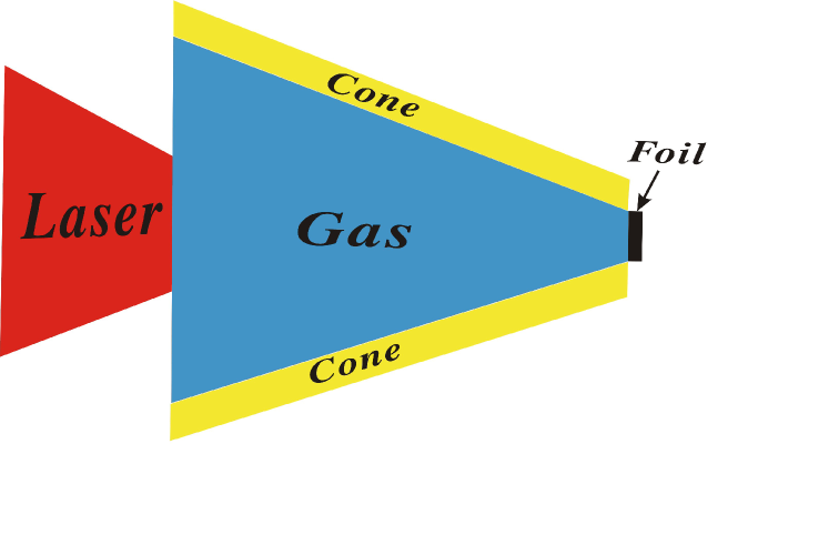
In this paper, we report that quasi-monoenergetic proton beam with peak energy of 130MeV and maximum energy of 181 MeV can be generated from a gas-filled cone target irradiated by a CP Gaussian laser pulse at an intensity of . The gas-filled cone target, as shown in Fig.1, consists of a hollow cone filled with near-critical heavy-ion gas-plasma and a thin foil attached to the tip of the cone. Our results indicate that, comparing with that from a simple proton target, energetic protons with smaller energy spread and higher energy can be obtained. This result can be attributed to the much higher electron density and temperature behind the foil and the small transverse size of the foil. The energetic electrons are generated from the gas-plasma and accelerated by the enhanced laser pulse, which undergoes self-focusing in gas-plasma and is even focused by the tip of the cone. These energetic electrons can easily propagate through the thin foil to form a stronger sheath field behind the foil (than that behind a planar target). Since the foil has a small transverse size, the protons in the foil are accelerated in the homogenous sheath field, so that the protons are accelerated longitudinally forward with smaller energy spread. In contrary to TNSA acceleration, here energetic electrons originate mainly from the gas rather than the solid target.
II Simulation Parameters
We carried out simulation using a fully relativistic particle-in-cell code (KLAP2D) zheng2002 ; Yan et al. (2008).In simulations, the simulation box is , where is the laser wavelength, and contains cells. A CP laser pulse with a peak laser intensity of is normally incident from the left side, The pulse has a Gaussian radial profile with full width at half maximum and a trapezoidal shape longitudinally with flat top and ramps on both sides, where T is the laser period. The corresponding peak dimensionless laser amplitude is 9.8, where E, , c,, and e are the laser electric field, frequency, speed of light in the vacuum, electron mass, and charge, respectively. The GCT target, as shown in Fig.1, consists of electrons, protons, and heavy carbon ions.
The initial temperature of electrons, protons, and carbon ions is 10 eV. The cone has a width of , and is located in with the diameters of the left and right cone openings of and , respectively. For simplicity, the cone consists of carbon plasma with an electron density , where is the critical density. The carbon gas-plasma is full in the cone with density . The foil with wide and thick is placed at . It consists of a proton-carbon mixed plasma with an electron density , and the ratio of C:H=1:1.
III Simulation Results
A laser beam propagating in underdense plasma with a frequency smaller than the laser frequency undergoes relativistic self-focusingMori1988 ; Pukhov1996 ; Mori1997 ; Asthana2000 ; Tripathi2010 as soon as its total power P exceeds the critical value
| (1) |
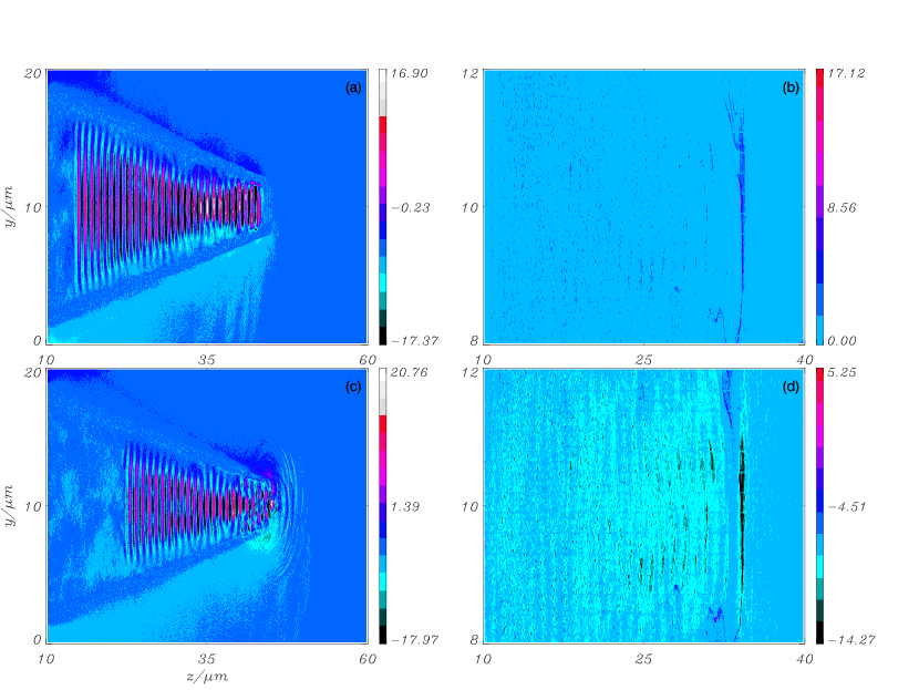
The self-focusing is due to the relativistic mass increase of plasma electrons and the ponderomotive expulsion of electrons from the pulse region. Both effects lead to a local decrease of plasma frequency and an increase in refractive index. The strong non-linear self-focusing of the laser pulse propagating in the near-critical gas-plasma at is shown in Fig.2(a). For clarity, only a part of the simulation box is shown. The spot size of the laser is focused to be smallest at , and the transverse electric field is enhanced to 17 there, which is 1.7 times higher than the initial laser electric field. The pulse retains its Gaussian radial profile, however, its spot size varies with the distance of propagation in a periodic manner. The smallest spot size at is about , while it varies to about at . This result is due to dynamic balance between diffraction and non-linear self-focusing, which is also in good agreement with the analysis of the paraxial ray approximationPANWAR2009 . When the laser propagates to the tip of the cone, it is even focused or squeezed by the tip of the cone for the small radius there, as is shown in Fig.2(b). The spot size is focused to about at the tip of the cone(), with the transverse electric field as high as 20 there.
The electrons that are initially at the front of the pulse are more efficiently accelerated as the pulse undergoes intensity enhancement due to self-focusing. Strong flows of relativistic electrons, axially comoving with the laser pulse, are observed in the simulation, as shown in Fig.2(b)and Fig.2(d). The maximum electron density near the axis is as high as , and the longitudinal electron current is about (negative due to negative electron charge). These energetic electrons then transport through the thin foil and form a strong backside sheath field there.
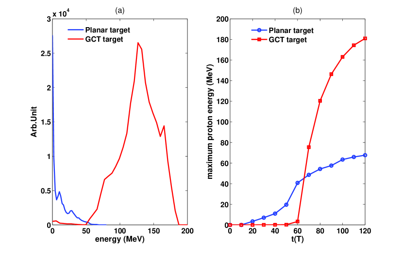
Fig.3(a) shows the energy spectrum of the proton bunches behind the targets in the two cases at . For the case shown, the maximum energy for the GCT target is about 181 MeV, which is nearly three times higher than that of the planar target(65MeV)under the same conditions. The energy conversion efficiencies from laser to protons are and for GCT and planar targets at , respectively. For the GCT target, due to the small transverse size of the foil where the sheath field is homogenous, the energy spectrum of the proton bunch has a quasi-monoenergetic peak with energy dispersion of about .
In contrast, the energy spectrum from the planar target is much broadened due to multidimensional effects such as hole boring and other instabilities. The evolution of the maximum proton energy is shown in Fig.3(b). For the planar target, as the laser impinges on the target at (the planar target is initially located at ), the maximum proton energy increases earlier than the GCT target(for which the laser impinges on the foil at ). However, as the electrostatic field at the place of the proton layer is much weaker for the planar target(see in Fig.4(a)), the increase of proton energy is much slower than the GCT target. For the GCT target, the maximum proton energy increases rapidly from 3.3MeV to 120MeV in only 20T(from to ), which is attributed to the strong electrostatic field during that time. At later time, the maximum proton energies in both cases remain almost constant.
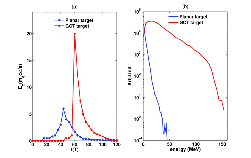
Evolutions of the electrostatic fields at the place of the proton layer for the planar and GCT targets are shown in Fig.4(a), which explains the energy enhancement of GCT target in Fig.3(b). The electrostatic fields straight up quickly at for the GCT target when the laser impinges on the target, because the energetic electrons generated from the gas-plasma reach the back side of the foil at and establish a strong sheath field there(see in Fig.5(a)). The maximum electrostatic field is about 20 for GCT target at , which is about 3.3 times higher than the planar target(6 at ). Since the energetic electrons expand away quickly, the electric fields decrease quickly after reaching the maximum for both cases. The electron energy spectrums behind the targets at t=50T for planar target and t=80T for GCT target are shown in Fig.4(b), at both times when the maximum energy of the electrons behind the targets is highest . We can see that the electron temperature and density are higher for the GCT target , which will result in a higher longitudinal field and eventually higher proton energy, as shown in Fig.4(a) and Fig.3(a).
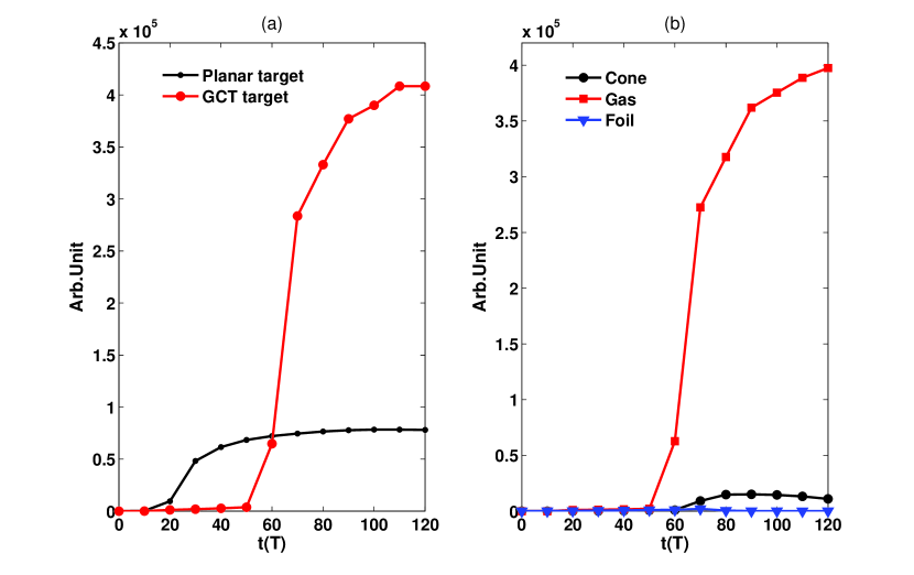
Since the TNSA mechanism depends strongly on the charge seperation field established by the energetic electrons, it is of interest to investigate the electron number behind the target. Fig.5(a) shows the time evolution of electron number behind the planar and GCT targets. For both cases, the electron numbers initially increase after the laser irradiates on the targets, and then flatten out. For GCT target, the electron number is nearly 5 times higher than the planar target at . From Fig.5(b) we can see the energetic electrons are almost generated from the gas-plasma ( of the total number), while only a small number of the electrons are from the cone ( of the total number). This result indicates that with the GCT target the efficiency of proton acceleration is determined by the electrons generated from the gas, which is quite different from the planar target(the electrons are from the target itself).
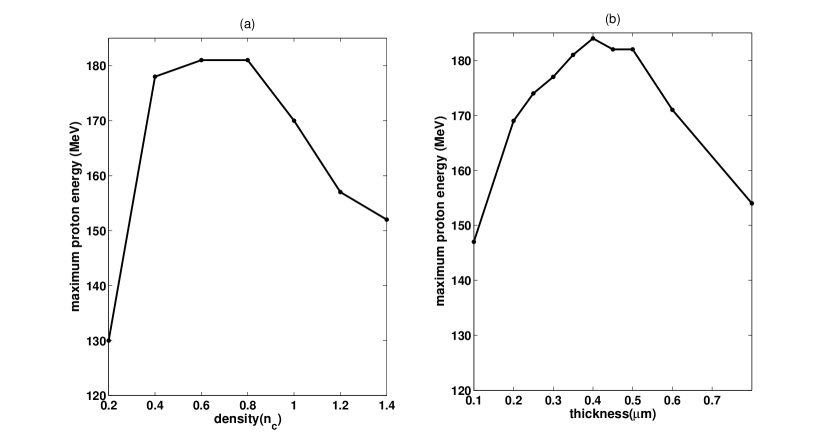
The effects of the gas-plasma density and the foil thickness of the GCT target are shown in Fig.6. It is found that the maximum proton energy remains almost the same(near 180MeV) while the gas-plasma density is between and , and the foil thickness is between and . These simulation results demonstrate that our acceleration scheme is robust. On the other hand, for the gas-plasma density, over-high gas-plasma density will result in much depletion of laser pulse, while over-low gas-plasma density will leads fewer enegertic electrons behind the foil, both will result in a decrease of the maximum proton energy. For the foil thickness, thin foils proved to be more efficient for ion acceleration in TNSA by hot-Electron recirculationMackinnon2002 , but over-thin foil will result in a quick expanding of the electrons, which will also result in a lower proton energy.
We have also stimulated the interaction of a Linear polarized(LP) laser pulse with a GCT target at the same intensity, while the other parameters are the same as in Fig.1. Our simulations results verify that similar phenomenon can also be observed with the LP laser pulse. A quasi-monoenergetic proton beam with peak energy of 139 MeV and maximum energy of 185 MeV can be generated. This indicates that our acceleration scheme can be also efficient for the LP laser pulse.
IV Conclusion
In conclusion, proton acceleration from a GCT target is proposed to enhance the ion energy. A quasi-monoenergetic proton bunch with peak energy of 130MeV and maximum energy of 181MeV is achieved by using the GCT target at laser intensity of . It is nearly three times higher than that from the planar target. This result is attributed to a stronger electrostatic field behind the foil, which is formed by the energetic electrons generated and accelerated by the enhanced laser pulse in the gas-plasma. The effects of the gas-plasma density and the foil thickness have been investigated. The results demonstrate that our acceleration scheme is robust. Such GCT target may be difficult to make at present, however, with the rapid advance in nanofabrication technology such a small conical channel filled with gas-plasma should be realizableOstrikov2005 . Accordingly, the GCT target can remarkably reduce the cost of a laser driven ion accelerator in the applications such as cancer therapy.
Acknowledgements.
This work was supported by National Nature Science Foundation of China (Grant Nos. 10935002,10835003,11025523) and National Basic Research Program of China (Grant No. 2011CB808104). XQY would like to thank the support from the Alexander von Humboldt Foundation.References
- Borghesi et al. (2002) M. Borghesi, D. H. Campbell, A. Schiavi, M. G. Haines, O. Willi, A. J. MacKinnon, P. Patel, L. A. Gizzi, M. Galimberti, R. J. Clarke, F. Pegoraro, H. Ruhl, and S. Bulanov , Phys. Plasmas 9, 2214 (2002).
- Naumova et al. (2009) N. Naumova, T. Schlegel, V. T. Tikhonchuk, C. Labaune, I. V. Sokolov, and G. Mourou, Phys. Rev. Lett 102, 025002 (2009).
- Roth et al. (2001) M. Roth, T. E. Cowan, M. H. Key, S. P. Hatchett, C. Brown, W. Fountain, J. Johnson, D. M. Pennington, R. A. Snavely, S. C. Wilks, K. Yasuike, H. Ruhl, F. Pegoraro, S. V. Bulanov, E. M. Campbell, M. D. Perry, and H. Powell, Phys. Rev. Lett 86, 436 (2001).
- Temporal et al. (2002) M. Temporal, J. J. Honrubia, and S. Atzeni, Phys. Plasmas 9, 3098 (2002).
- S.V.Bulanov and S. (2002) S. V. Bulanov and V. S. Khoroshkov, Plasma Phys. Rep 28, 453 (2002).
- (6) J. Denavit, Phys. Rev. Lett 69, 3052 (1992).
- (7) L. O. Silva, M. Marti, J. R. Davies, R. A. Fonseca, C. Ren, F. Tsung, and W. B. Mori, Phys. Rev. Lett 92, 015002 (2004).
- Yan et al. (2008) X. Q. Yan, C. Lin, Z. M. Sheng, Z. Y. Guo, B. C. Liu, Y. R. Lu, J. X. Fang, and J. E. Chen, Phys. Rev. Lett 100, 135003 (2008).
- (9) Z. M. Sheng, K. Mima, Y. Sentoku, K. Nishihara, and J. Zhang , Phys. Plasmas 9, 3147 (2002).
- Henig et al. (2009a) A. Henig, D. Kiefer, K. Markey, D. C. Gautier, K. A. Flippo, S. Letzring, R. P. Johnson, T. Shimada, L. Yin, B. J. Albright, K. J. Bowers, J. C. Fernández, S. G. Rykovanov, H.-C. Wu, M. Zepf, D. Jung, V. Kh. Liechtenstein, J. Schreiber, D. Habs, and B. M. Hegelich, Phys. Rev. Lett 103, 045002 (2009a).
- Qiao et al. (2009) B. Qiao, M. Zepf, M. Borghesi, and M. Geissler, Phys. Rev. Lett 102, 145002 (2009).
- Yan et al. (2009) X. Q. Yan, H. C. Wu, Z. M. Sheng, J. E. Chen, and J. Meyer-ter-Vehn, Phys. Rev. Lett 103, 135001 (2009).
- (13) E. Fourkal, I. Velchev, and C. M. Ma, Phys. Rev. E 71, 036412 (2005).
- Fuchs et al. (2006) J. Fuchs, P. Antici, E. D’Humieres, E. Lefebvre, M. Borghesi, E. Brambrink, C. A. Cecchetti, M. Kaluza, V. Malka, M. Manclossi, S. Meyroneinc, P. Mora, J. Schreiber, T. Toncian, H. Pépin, and P. Audebert, Nat. Phys 2, 48 (2006).
- (15) S. C. Wilks, A. B. Langdon, T. E. Cowan, M. Roth, M. Singh, S. Hatchett, M. H. Key, D. Pennington, A. MacKinnon, and R. A. Snavely, Phys. Plasmas 8, 542 (2001).
- Snavely et al. (2000) R. A. Snavely, M. H. Key, S. P. Hatchett, T. E. Cowan, M. Roth, T. W. Phillips, M. A. Stoyer, E. A. Henry, T. C. Sangster, M. S. Singh, S. C. Wilks, A. MacKinnon, A. Offenberger, D. M. Pennington, K. Yasuike, A. B. Langdon, B. F. Lasinski, J. Johnson, M. D. Perry, and E. M. Campbell, Phys. Rev. Lett 85, 2945 (2000).
- Schwoerer et al. (2006) H. Schwoerer, S. Pfotenhauer, O. Jäckel, K.-U. Amthor, B. Liesfeld, W. Ziegler, R. Sauerbrey, K. W. D. Ledingham, and T. Esirkepov, Nature 439, 445 (2006).
- Hegelich et al. (2006) B. M. Hegelich, B. J. Albright, J. Cobble, K. Flippo, S. Letzring, M. Paffett, H. Ruhl, J. Schreiber, R. K. Schulze, and J. C. Fernández, Nature 439, 441 (2006).
- (19) R. Kodama, P. A. Norreys, K. Mima, A. E. Dangor, R. G. Evans, H. Fujita, Y. Kitagawa, K. Krushelnick, T. Miyakoshi, N. Miyanaga, T. Norimatsu, S. J. Rose, T. Shozaki, K. Shigemori, A. Sunahara, M. Tampo, K. A. Tanaka, Y. Toyama, T. Yamanaka, and M. Zepf, Nature (London) 412, 798 (2001).
- (20) Z. L. Chen, R. Kodama, M. Nakatsutsumi, H. Nakamura, M. Tampo, K. A. Tanaka, Y. Toyama, T. Tsutsumi, and T. Yabuuchi, Phys. Rev. E 71, 036403 (2005).
- (21) R. B. Stephens, S. P. Hatchett, R. E. Turner, K. A. Tanaka, and R. Kodama, Phys. Rev. Lett 91, 185001 (2003).
- (22) L. V. Woerkom, K. U. Akli, T. Bartal, F. N. Beg, S. Chawla, C. D. Chen, E. Chowdhury, R. R. Freeman, D. Hey, M. H. Key, J. A. King, A. Link, T. Ma, A. J. MacKinnon, A. G. MacPhee, D. Offermann, V. Ovchinnikov, P. K. Patel, D. W. Schumacher, R. B. Stephens, and Y. Y. Tsui, Phys. Plasmas 15, 056304 (2008).
- (23) R. J. Mason, Phys. Rev. Lett 96, 035001 (2006).
- (24) A. L. Lei, K. A. Tanaka, R. Kodama, G. R. Kumar, K. Nagai, T. Norimatsu, T. Yabuuchi, and K. Mima, Phys. Rev. Lett 96, 255006 (2006).
- (25) J. Pasley, and R. Stephens, Phys. Plasmas 14, 054501 (2007).
- (26) H. Sakagami, T. Johzaki, H. Nagatomo, and K. Mima, Laser Part. Beams 24, 191 (2006).
- (27) H. Nagatomo, T. Johzaki, T. Nakamura, H. Sakagami, A. Sunahara, and K. Mima, Phys. Plasmas 14, 056303 (2007).
- (28) M. H. Key, Phys. Plasmas 14, 055502 (2007).
- (29) H. B. Cai, K. Mima, W. M. Zhou, T. Jozaki, H. Nagatomo, A. Sunahara, and R. J. Mason, Phys. Rev. Lett 102, 245001 (2009).
- (30) J. A. King, K. U. Akli, R. R. Freeman, J. Green, S. P. Hatchett, D. Hey, P. Jamangi, M. H. Key, J. Koch, K. L. Lancaster, T. Ma, A. J. MacKinnon, A. MacPhee, P. A. Norreys, P. K. Patel, T. Phillips, R. B. Stephens, W. Theobald, R. P. J. Town, L. Van Woerkom, B. Zhang, and F. N. Beg, Phys. Plasmas 16, 020701 (2009).
- (31) J. S. Green, K. L. Lancaster, K. U. Akli, C. D. Gregory, F. N. Beg, S. N. Chen, D. Clark, R. R. Freeman, S. Hawkes, C. Hernandez-Gomez, H. Habara, R. Heathcote, D. S. Hey, K. Highbarger, M. H. Key, R. Kodama, K. Krushelnick, I. Musgrave, H. Nakamura, M. Nakatsutsumi, N. Patel, R. Stephens, M. Storm, M. Tampo, W. Theobald, L. Van Woerkom, R. L. Weber, M. S. Mei, N. C. Woolsey, and P. A. Norreys, Nat. Phys 3, 853 (2007).
- (32) J. Rassuchine, E. d Humières, S. D. Baton, P. Guillou, M. Koenig, M. Chahid, F. Perez, J. Fuchs, P. Audebert, R. Kodama, M. Nakatsutsumi, N. Ozaki, D. Batani, A. Morace, R. Redaelli, L. Gremillet, C. Rousseaux, F. Dorchies, C. Fourment, J. J. Santos, J. Adams, G. Korgan, S. Malekos, S. B. Hansen, R. Shepherd, K. Flippo, S. Gaillard, Y. Sentoku, and T. E. Cowan, Phys. Rev. E 79, 036408 (2009).
- (33) Y. Sentoku, K. Mima, H. Ruhl, Y. Toyama, R. Kodama, and T. E. Cowan, Phys. Plasmas 11, 3083 (2004).
- (34) T. Nakamura, T. Nakamura, H. Sakagami, T. Johzaki, H. Nagatomo, K. Mima, and J. Koga, Phys. Plasmas 14, 103105 (2007).
- (35) L. H. Cao, W. Yu, M. Y. Yu, H. Xu, X. T. He, Y. Q. Gu, Z. J. Liu, J. H. Li, and C. Y. Zheng, Phys. Rev. E 78, 036405 (2008).
- (36) A. Pukhov, and J. Meyer-ter-Vehn, Phys. Rev. Lett 76, 21 (1996).
- (37) W. B. Mori, C. Joshi, J. M. Dawson, D. W. Forslund, and J. M. Kindel, Phys. Rev. Lett 60, 1298 (1988).
- (38) W. B. Mori, IEEE J. Quant. Electron 33, 1942 (1997).
- (39) M. V. Asthana, A. Giulietti, D. Giulietti, L. A. Gizzi, and M. S. Sodha, Laser Part. Beams 18, 399 (2000).
- (40) D. Tripathi, L. Bhasin, R. Uma, and V. K. Tripathi, Phys. Plasmas 17, 113113 (2010).
- (41) A. Panwar, and A. K. sharma, Laser Part. Beams 27, 249 (2009).
- (42) A. J. Mackinnon, Y. Sentoku, P. K. Patel, D. W. Price, S. Hatchett, M. H. Key, C. Andersen, R. Snavely, and R. R. Freeman, Phys. Rev. Lett 88, 215006 (2002).
- (43) K. Ostrikov, Rev. Mod. Phys 77, 489 (2005).