Electric Polarization Induced by Néel Order without Magnetic Superlattice: Experimental Study of Cu3Mo2O9 and Numerical Study of a Small Spin Cluster
Abstract
We clarify that the antiferromagnetic order in the distorted tetrahedral quasi-one-dimensional spin system induces electric polarization. In this system, the effects of low dimensionality and magnetic frustration are expected to appear simultaneously. We obtain the magnetic-field-temperature phase diagram of Cu3Mo2O9 by studying the dielectric constant and spontaneous electric polarization. Around the tricritical point at 10 T and 8 K, the change in the direction of electric polarization causes a colossal magnetocapacitance. We calculate the charge redistribution in a small spin cluster consisting of two magnetic tetrahedra to demonstrate the electric polarization induced by the antiferromagnetism.
Since the discovery of a strong magnetoelectric effect in TbMnO3, [1] multiferroics in transition-metal oxides have been extensively studied. [2] In the cases of the inverse Dzyaloshinskii-Moriya interaction in a spiral spin structure [3, 4, 5] and the inverse Kanamori-Goodenough interaction in a collinear one, [6] the formation of the magnetic superlattice plays an essential role in the magnetic-order-induced multiferroics. Geometrical magnetic frustration also plays an important role as the origin of a nontrivial spin configuration that breaks the spatial inversion symmetry. In this study, we demonstrate that the distorted tetrahedral spin system has the potential to show multiferroic behavior without any magnetic superlattice formation. We focus on the dielectric properties induced by an antiferromagnetic (AFM) spin order in Cu3Mo2O9 and discuss the possibility of the multiferroic behavior in an AFM spin system on the basis of the theory of the charge redistribution in frustrated Mott insulators. [7, 8]
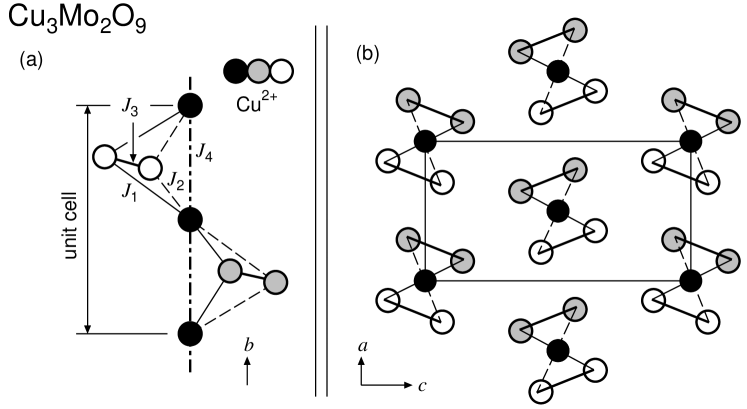
Cu3Mo2O9 has two distorted tetrahedral quasi-one-dimensional quantum spin systems of = 1/2 spins along the -axis in its orthorhombic unit cell [Figs. 1(a) and 1(b)]. This compound has geometrical magnetic frustrations due to the tetrahedral spin alignment and quasi-one-dimensionality simultaneously. This compound undergoes an AFM phase transition at = 7.9 K without a magnetic field. [9, 10] Inelastic neutron scattering measurements clarify the hybridization effects due to the and superexchange interactions between two elemental magnetic excitations, i.e., that of the quasi-one-dimensional AFM spin system originating from the (= 4.0 meV) superexchange interactions and that of the isolated AFM spin dimers originating from the (= 5.8 meV) ones. [11, 12]
The AFM spin-wave branch arises linearly from zero energy at the magnetic zone center of = (0, 1, 1), which is also the nuclear zone center below and above . This magnetic branch is strongly dispersive along the direction. This dispersion curve and the two-spinon continuum above mass gap energy = 1.2 meV are typical features of a quasi-one-dimensional AFM spin system. There are no indications of the formation of commensurate or incommensurate magnetic superstructures, at least at our experimental resolution.
To obtain the magnetic-field-temperature (-) phase diagram, we measured the and dependences of the dielectric constant and the electric polarization under an electric field along the -axis ( = or ) of Cu3Mo2O9. In this letter, we focus on the effects of the magnetic field along the -axis. We prepared a platelike single crystal of Cu3Mo2O9 whose cross section and thickness are typically about 60 mm2 and 0.4 mm, respectively. To form a capacitor, the faces were coated with gold and attached using two gold wires. The capacitance, of which the typical value was on the order of 10 pF, was measured using an impedance analyzer (Yokogawa-Hewlett-Packard 4192A). was obtained from the capacitance at 100 kHz with a peak voltage of 1 V. To confirm the ferroelectric behavior, the electric polarization-electric field loop (- loop) at 1 Hz was recorded using a modified Sawyer-Tower circuit with a peak voltage of about 200 V. The magnetic field was applied using a superconducting magnet (Oxford Instruments, Teslatron S14/16), of which the maximum magnetic field was 16 T, and a variable-temperature insert cryostat was used to set the temperature from 1.5 to 300 K.


Figures 2(a) and 2(b) show the typical dependences of ( = or ) under a fixed (- curves), respectively, each of which has a (local) maximum at . The values of against are plotted in the - phase diagram by the solid symbols in Fig. 3. Figures 2(c) and 2(d) show the typical dependences of at 8 and 4 K (- curves), respectively. At 8 K, as shown in Fig. 2(c), the - and - curves have one and two peaks, respectively. These are plotted in the phase diagram by open symbols in Fig. 3. We observed a colossal magnetocapacitance (800%) at 8 K in Fig. 2(c). Here the maximum slightly above 10 T was compared with the minimum at approximately 6 T. This magnetocapacitance is larger than the maximum one reported before. [13] This is probably due to strong fluctuations around the tricritical point at (, ) = (10 T, 8 K) in the - phase diagram. At 4 K, as shown in Fig. 2(d), gradually decreases with increasing above 6 T. At about 8 T, a small peak is observed in the - curve, which is indicated by an arrow and is plotted in Fig. 3 by an open symbol. Around this , shows a sudden increase.
At 4 K, as shown in the inset of Fig. 2(d), the - curve under a zero-magnetic-field cooling process rapidly decreases with increasing from 0 T. This anomaly is not observed during the reduction of the magnetic field. We plot , where this hysteresis effect disappears, in Fig. 3. Around this , the dependence of the magnetization (the - curve) along the -axis shows a small jump with a magnetic-field hysteresis effect. [9] In some multiferroic materials, a change in electric polarization accompanied by a jump of the magnetization has been reported. [1, 14] These facts and the present result showing that the peaks in the - curves become sharp at 6 T [Figs. 2(a) and 2(b)] suggest that the zero-field ground state contains some fluctuations, which is consistent with our picture describing the canted antiferromagnetism at zero and finite magnetic fields. [9, 15] In this picture, the canting direction of the spin moment contains randomness after a zero-field cooling process. The jump of the magnetization in finite magnetic fields is understood as the alignment of the canting direction. Once it occurs, it survives even at a zero magnetic field because of the internal magnetic field, indicating the possibility of the magnetic-field hysteresis effect in this system.
Together with the additional data and phase boundary obtained from the dependence of the specific heat under , [10] we obtain the - phase diagram in Fig. 3. One can see that the increase in at 6 T [Figs. 2(a) and 2(b)] corresponds to the change in under . [10] We emphasize here that the peak in the - (-) curve is not necessarily in agreement with the critical temperature (magnetic field) of the phase transition. Therefore, it is natural that the plots in the - phase diagram obtained from the data of do not perfectly trace the phase boundary obtained using specific heat. We conclude that the phase diagram contains four different phases.
To observe the spontaneous electric polarization directly, we measured the - loop. Figures 4(a) and 4(b) show the typical results at various and . At 0 T, as shown in Fig. 4(b), the - loop below shows clear ferroelectric behavior. The spontaneous electric polarization density (500 C/m2) is close to that of TbMnO3. [1] As shown in Fig. 4(a), the - loop at 0 T does not show ferroelectric behavior. Thus, we conclude that Cu3Mo2O9 at 0 T below is in the ferroelectric phase with spontaneous electric polarization along the -axis [the FE( phase]. This result is consistent with the following facts: in Figs. 2(a) and 2(b) and a strong microwave absorption was observed at approximately at a zero magnetic field.
Figure 4(b) shows the dependence of the - loop. At 5 T, the - loop indicates the FE( phase because it is similar to that at 0 T (data not shown). Instead of the closed - loop at 13 T, the ferroelectric - loop was observed at 14 T. The at 13 T becomes about ten times larger than at 6 T [Fig. 2(a)]. The at 13 T becomes about ten times smaller than at 6 T [Fig. 2(b)]. Judging from these results, we confirm the FE( phase at 13 T. The spontaneous electric polarization density (800 C/m2) is comparable to that of DyMnO3 at 21 K. [13]
As shown in Fig. 2(d), both the - and - curves show anomalies at approximately 8 T at 4 K. As shown in Fig. 4(a), the - curve suggests a double hysteresis loop at 7.9 T. This effect is explained by the electric-field-induced electric polarization and indicates strong fluctuations around the phase boundary. We conclude that the change in the direction of the spontaneous electric polarization occurs at the phase boundary running from (, ) = (8 T, 2 K) to (10 T, 8 K). At approximately 8 T, a change in the electron-spin-resonance spectrum was reported. [16] Together with the phase transition temperatures obtained from the dependences of under various , [10] we conclude that this compound is a multiferroic material.
In many cases, the origin of multiferroicity has been discussed on the basis of the formation of the magnetic superlattice. Unfortunately, the spin structure below at 0 T has not been clarified yet. However, we emphasize again that the AFM long-range order below has been established by the magnetic dispersion curve obtained from inelastic neutron scattering. [12] Moreover, the anisotropic magnetization has been quantitatively explained on the basis of a weakly canted AFM long-range order. [9]

The point of discussion is how the AFM long-range order induces ferroelectricity. In the following, we focus on the charge redistribution effects caused by the three-spin ring exchange interaction in geometrically frustrated Mott insulators, proposed by Bulaevskii et al. [7, 8] We demonstrate that the spin cluster in Fig. 5 has the potential for multiferroic behavior as a result of the antiferroelectric (AFE) polarization at zero electric field and the ferrielectric (FRE) polarization under an electric field. This is the minimum system that maintains the tetrahedral spin arrangement and the inversion center at spin site #4 simultaneously. The formation of the magnetic superlattice is impossible.
We treat this system as a Mott insulator. The electronic band from orbitals in Cu2+ ions is half-filled. In the limit of the strong on-site Coulomb repulsion , where the charge degrees of freedom are frozen, the system can be mapped on the quantum spin system. The spin Hamiltonian is given by
| (1) |
where the sum in the first term on the right-hand side runs over all the possible spin pairs ( and at the # and # sites, respectively) connected through the hopping parameter . The values of correspond to the exchange interactions in Fig. 5. The second term on the right-hand side is the magnetic energy from the local magnetic field at the # site, where and are the factor and Bohr magneton, respectively.
On the basis of the interchain interaction in Cu3Mo2O9, [12] we set the values = = 1 meV, = = 5.8 meV, = 4 meV, and = 2. We introduced the staggered magnetic field along the quantization axis working on only the #1 and #4 sites. induces the AFM spin order at the site on the spatial inversion symmetry, i.e., this site is on the anti-inversion center in the term of the magnetic space group. Using the exact diagonalization, we calculated and the charge redistribution at spin site #, [7, 8]
| (2) |
in the periodic-boundary six-spin cluster at 0 K. Here, the sum on the right-hand side runs over all the possible spin triangles connected through exchange interactions. The amplitude of the electric polarization is proportional to ,

As shown in Figs. 6(a) and 6(b), and increase larger with increasing . Even in this case, the spins at the sites #2, #3, #5, and #6 still form nonmagnetic spin dimers. We plot in Fig. 6(b) because we could not precisely estimate , and calculations in larger systems are necessary to discuss the origin of the finite without the staggered magnetic field because of the strong system-size dependence.
Under a uniform electric field, the exchange interaction slightly changes as a result of the breaking of the spatial inversion symmetry. [17] If the exchange interactions of the nonmagnetic spin dimers are different ( = 5.0 meV and = 6.6 meV), we obtain a finite net electric dipole moment as a result of the FRE alignment of the electric dipoles ( ) even though is not changed. From this calculation, we conclude that the tetrahedral quasi-one-dimensional spin system has the potential to exhibit AFM-AFE and AFM-FRE type multiferroic behaviors. The finite net electric dipole moment appears when the time and spatial inversion symmetries are broken.
In this study, we demonstrate the possibility of electric polarization induced by the AFM long-range order in a distorted tetrahedral quasi-one-dimensional spin system. As experimental evidence, the - phase diagram of Cu3Mo2O9 under a magnetic field along the -axis was shown by studying the temperature and magnetic-field dependences of the dielectric constant. The ferroelectric behavior was observed in the polarization-electric-field loop and a change in the polarization direction was observed. Around the tricritical point at (10 T, 8 K), a colossal magnetocapacitance was observed. We showed that a six-spin cluster that corresponds to a tetragonal quasi-one-dimensional spin system has the potential to become an AFM-AFE multiferroic state without the formation of a magnetic superlattice. The possibility of the AFM-FRE multiferroic state under an electric field was discussed.
Acknowledgments
This work is partly supported by a Grants-in-Aid for Scientific Research (C) (No. 40296885) and on Priority Area (No. 19052005) from the Ministry of Education, Culture, Sports, Science and Technology of Japan (MEXT). We thank Dr. N. Terada of NIMS, Dr. Y. Nishiwaki and Prof. T. Nakamura of Shibaura Institute of Technology, and Prof. T. Goto, Dr. M. Akaki, and Prof. H. Kuwahara of Sophia University for helpful discussions. We also wish to acknowledge the technical assistance of Mr. R. Kino and Mr. M. Suzuki.
References
- [1] T. Kimura, T. Goto, H. Shintani, K. Ishizawa, T. Arima, and Y. Tokura: Nature 426 (2003) 55.
- [2] For review, S.-W. Cheong and M. Mostovoy: Nat. Mater. 6 (2007) 13.
- [3] H. Katsura, N. Nagaosa, and A. V. Balatsky: Phys. Rev. Lett. 95 (2005) 057205.
- [4] M. Kenzelmann, A. B. Harris, S. Jonas, C. Broholm, J. Schefer, S. B. Kim, C. L. Zhang, S.-W. Cheong, O. P. Vajk, and J. W. Lynn: Phys. Rev. Lett. 95 (2005) 087206.
- [5] M. Mostovoy: Phys. Rev. Lett. 96 (2006) 067601.
- [6] T. Arima, T. Goto, Y. Yamasaki, S. Miyasaka, K. Ishii, M. Tsubota, T. Inami, Y. Murakami, and Y. Tokura: Phys. Rev. B 72 (2005) 100102R.
- [7] L. N. Bulaevskii, C. D. Batista, M. V. Mostovoy, and D. I. Khomskii: Phys. Rev. B 78 (2008) 024402.
- [8] D. I. Khomskii: J. Phys.: Condens. Matter 22 (2010) 164209.
- [9] T. Hamasaki, N. Ide, H. Kuroe, T. Sekine, M. Hase, I. Tsukada, and T. Sakakibara: Phys. Rev. B 77 (2008) 134419.
- [10] T. Hamasaki, H. Kuroe, T. Sekine, M. Akaki, H. Kuwahara, and M. Hase: J. Phys.: Conf. Ser. 200 (2010) 022013.
- [11] H. Kuroe, T. Hamasaki, T. Sekine, M Hase, K. Oka, T. Ito, H. Eisaki, and M. Matsuda: J. Phys.: Conf. Ser. 200 (2010) 022028.
- [12] H. Kuroe, T. Hamasaki, T. Sekine, M Hase, K. Oka, T. Ito, H. Eisaki, K. Kaneko, N. Metoki, M. Matsuda, and K. Kakurai: Phys. Rev. B 83 (2011) 184423.
- [13] T. Goto, T. Kimura, G. Lawes, A. P. Ramirez, and Y. Tokura: Phys. Rev. Lett. 92 (2004) 257201.
- [14] T. Kimura, J. C. Lashley, and A. P. Ramirez: Phys. Rev. B 73 (2006) 220401R.
- [15] M. Hase, H. Kitazawa, K. Ozawa, T. Hamasaki, H. Kuroe, and T. Sekine: J. Phys. Soc. Jpn. 77 (2008) 034706.
- [16] S. Okubo, T. Yoshida, M. Fujisawa, T. Sakurai, H. Ota, T. Hamasaki, H. Kuroe, T. Sekine, M. Hase, K. Oka, T. Ito, and H. Eisaki: J. Low Temp. Phys. 159 (2010) 32.
- [17] M. Trif, F. Troiani, D. Stepanenko, and D. Loss: Phys. Rev. B 82 (2010) 045429.