201114223705 \doinumber10.5488/CMP.14.23705 \addressLviv Polytechnic National University, 12 Bandera Str., 79013 Lviv, Ukraine \authorcopyrightB.A. Lukiyanets, D.V. Matulka, I.I. Grygorchak, 2011
Quantum mechanic tunneling and efficiency of Faraday current-generating process in porous nanostructures
Abstract
Thermodynamics and kinetics of lithium intercalation into C–SiO2 nanocomposites are investigated. Dependencies of both differential capacity and intercalation kinetics on the nanocomposite size are established. The processes are analyzed in terms of the impedance model. The obtained results are explained based on the quantum effect of interference blockade of electron tunneling into a nonmetallic nanoparticle. Propositions for the new electrochemical energy storage technology are presented. \keywordsnanoobject, electron state, tunneling, intercalation \pacs71.20, 71.24, 73.40, 73.63
Abstract
В роботi дослiджено термодинамiчнi та кiнетичнi закономiрностi процесу лiтiєвої iнтеркаляцiї C–SiO2 нанокомпозитiв. Встановлена залежнiсть як для диференцiйної ємностi, так i для кiнетичних параметрiв процесу вiд розмiрiв нанокомпозитiв. Згiдно з результатами теоретичного аналiзу, отриманi залежностi є наслiдком квантово-механiчного ефекту iнтерференцiйної блокади електронного тунелювання в неметалiчну наночастинку. Наведена iмпедансна модель процесiв та параметрична iдентифiкацiя. Представлена нова технологiя електрохiмiчних генераторiв енергiї. \keywordsнанооб’єкт, електронний стан, тунелювання, iнтеркаляцiя
1 Introduction
A growing interest to nanostructures has been observed lately. These structures possess a number of unique physical properties that turned out to be quite promising from the viewpoint of their practical applications in electronics. For instance, nanotechnology may be one of the effective ways of solving an urgent technical problem of producing a cathode material with high specific energy. Really, application of the nanodispersed FeS2 in an energy storage device with the lithium anode increases the specific capacity by about 20% in comparison with the coarse-grained homologue [1], and the nanosized -Fe2O3 possesses high recirculated capacity 200 mAhour/g and good cycling in the range of 1.5–4.0 V regarding Li+/Li in comparison with the macrostructured -Fe2O3 , -Fe3O4 , and -Fe2O3 [2].
On the other hand, the urgency of searching for new cathode materials is closely connected with lack of raw materials for traditional cathode-active ones [3]. We think that production of new cathode materials on the basis of cheap and ecologically clean substances due to the dimensional (nano) effects is a rational way of making the energy storage devices. Beneficial application thereof obviously depends on the degree of understanding the physical processes in nanostructures. The paper is devoted to consideration of the above problem.
2 Samples and experimental setup
Let us consider a silicon dioxide SiO2 which is a widespread ecologically pure material. The nanosize silicon dioxide intercalated by Li+ belongs to the groups of materials usable in developing the high capacitive energy storage devices.
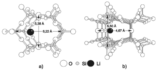
It is well known [4] that silicon dioxide occurs in three structural forms, i.e., quartz, tridymite and cristobalite. None of them in macroscale is usable as a cathode-active material [5]. This is connected with the extremely low level of density of ionised defects at a room temperature and low concentration of the shallow level of trapping, although ‘‘guest’’ positions for the introduced lithium are well defined by nanodispersed tridymite structural channels (figure 1). The situation has drastically changed with the transition to the nanosize SiO2 with lithium introduced into its structural channels. In this case, the density of states at Fermi level can become considerable due to surface states (the ‘‘electrochemical grafting’’ concept [2, 6]) and due to sharp decrease of the diffusion resistance. Our quantum-mechanical calculations [7] have shown that the lithium penetration into the nanodispersed tridymite structural channels (figure 1) is an exothermal process.
The nanodispersed silicon dioxide used throughout experiments was obtained from the silicon tetrachloride by pyrogenic method in hydrogen-air jet in the reaction system with minimum turbulence at 10001500∘C.
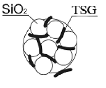
The size of the sedimentation fractions was analyzed both by small-angle X-ray dispersion [8] and by electron microscopy. Electrodes with surface area 0.5 cm2 on a nickel substrate were formed for electrochemical study. Composition of an electrode is defined by ratio active material (SiO2): conductive agent: cementing agent as 85% : 10% : 5%. The silicon dioxide mass does not exceed 1 mg. Structure of the electrodes is schematically shown in figure 2.
Thermodynamics and kinetics of the lithium intercalation were investigated in the three-electrode electrochemical cell with the monomolar LiBF4 solution in -butyrolactone. The impedance analysis was performed within the frequency range 10-2105 Hz using AUTOLAB device manufactured by ECO CHEMIE (Holland) equipped with FRA-2 and GPES computer programs. Galvanostatic ‘‘charge-discharge’’ cycles were realized by standard electronic circuit.
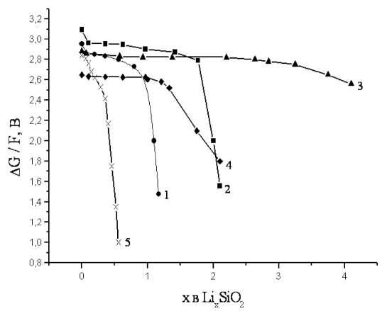
The electromotive force method [9] was used for thermodynamic analysis of the process. Figure 3 presents the dependence of differential capacity on ( is a number lithium per formular unit of a host material; is a relaxed value of voltage of the open circuit relative to lithium electrode depending content). It is seen that the current-generating reaction only for the nearly 9-nm nanoparticles undergoes the I-st type phase transition (jump of ) with the formation of a two-phase state. At defined, X-ray investigation fixes in LiSiO2 the NaCl-type phase in which oxygen anions form a face-centered cube and the ions Li+ and Si4+ occupy the octahedral hollows. The lattice parameter of a such phase is 4.02870.0009 Å. Figure 3 shows a researched current-generating reaction in the nanodispersed silicon dioxide [7] with the average size of the particles of the order of 16, 11, 9 and 5 nm intercalated with lithium content of . It is seen that the specific discharge capacity, specific energy, at for which discharge voltage is 1.5 V, essentially depend on the nanoparticle size (table 1). The maximum flow of the reaction takes place in case of the 9 nm size. What exactly has caused the situation?
| SiO2 with average size of particles 16 nm | SiO2 with average size of particles 11 nm | SiO2 with average size of particles 9 nm | SiO2 with average size of particles 5 nm | Macro-structured MnO2 (theory) [10] | Macro-structured CFx(theory) [10] | |
| specific capacity, mAhour/g |
648
|
1080
|
1890
|
324
|
310
|
860
|
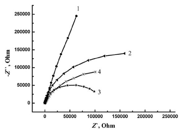
In order to analyse the Faraday’s current-generating reaction in various nanosized silicon dioxide, let us consider Nyquist diagrams presented in figure 4. They show a strong increase of the resistance of the charge transport (figure 4, curves 2, 4) for all sizes of nanoparticles (with the exception of the 9-nm size in which the kinetic mechanism takes place; curve 3) up to the practically full blockade of the process (curve 1). In other words, the interphase charge transport is a well-marked effect.
Herein below we present particular considerations that will enable us to comprehend the cause and circumstances at which this situation becomes possible.
3 Model
Faraday’s current-generating reaction is connected with penetration of an electron into the nanoporous hollow filled with lithium. Today, there are some investigations of the behavior of electrons in nanostructures. The researchers frequently use well-known quantum mechanical models. In particular, the effect of a resonant laser impulse irradiation on an electron within the system of two semiconductor dots was researched in [10]. Two interlinked rectangular wells that model the quantum dots were used. The paper shows that quantum dynamics of electron under the action of electromagnetic irradiation of nanostructure essentially depends not only on the behavior of the wave but also on geometric and energy characteristics of the dots. Resonant transition in three-barrier nanostructure was studied in [11]. Therein a one-dimensional model was used with three rectangular wells of various depth, i.e., like in paper [10], the potential on the whole is a nonanalytic function. However, the solutions of the problem (wave functions, energy levels) are known for each well. The effect of rearrangement of levels in the system may be taken into consideration from the procedure of matching the wave functions together at the border discontinuity of the potential.
As it follows from the above cited papers, as well as from several others, the present state of theoretical research of nanoobjects justifies the application of even the simplest models for the purpose of comprehending the physical effects therein.
Below we make a research within the simplest model of energy storage in nanosystems, namely, the electron tunneling into a nonmetallic nanoparticle in one-dimensional model ‘‘border-core-border’’ and b) model of porous nanostructure (or two-dimensional nanoparticle, nanotube)
3.1 One-dimensional model ‘‘border-core-border’’
In figure 5, within the framework of one-dimensional problem, the nanoparticle is presented by potential of a hollow with two potential barriers and which set off the hollow. Different thickness of such potentials should be regarded as effective potentials of particles of different sizes. Then electron with energy , moving from left to right, will be tunnels through a barrier a into the particle. The barrier shows itself mediately, namely through the electron de Broglie wave reflected from it.
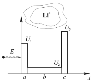
It is well known that at certain conditions, the tunneling probability of an electron through the system of two identical rectangular potential barriers reaches unity [12]. This is just the essence of resonant tunneling. This situation is observed for a subbarrier electron with the energy value coinciding with its virtual values in a well. This is caused by cancelation at superposition of the tunneled electron de Broglie wave into a well and the elastically reflected wave from the opposite barrier. Contrary to the traditional resonant tunneling problem through the both barriers, our interest was focused on tunneling into the hollow, i.e., tunneling through one of them, which turns out to be the essence of current-generating reaction.
Due to non-analyticity of the potential, it is presented as the sum of potentials:
| (1) |
i.e. all area is broken into intervals, in which the potentials are analytical functions (; ; ).
The solutions of the time-independent Schrodinger equation are of the form:
| (2) |
with ; index coincides with the notations of intervals in figure 5.
Thus, taking into account potential (1), , , , , where .
In our case, tunneling through a barrier is described by the tunneling probability . Thus, it is necessary to find the weight multipliers , of the corresponding wave functions. Taking into account the properties of the wave function (the absence of both the jump of the function and its derivative in any point) and matching such functions and their derivatives in the jump points of the potential one, yields a set of eight linear equations in , , , , , , , , (in due to the absence of the reflected wave in this interval). Analogue of such a system is shown below.
A standard procedure of numerical solution of the equations was used. In figure 6 (a) the logarithm of the tunneling probability on the nanoparticle size is presented at parameters nm, nm, eV, eV, eV, eV, eV, and in figure 6 (b) – at the same parameters with the only replacement of eV by eV. The replacement also describes the sub-barrier electron but with energy closer to the lower barrier top.

From figure 6 it follows:
-
•
The property of the tunneling probability as a function of the well thickness [] is its oscillation behavior. In the points of minimum, is practically equal to zero. Such behavior is a result of superposition of the wave tunneled into and the elastic wave reflected from the barrier .
-
•
The increased thickness of an opposite barrier () decreases the tunneling probability without changing its periodicity.
Thus, depending on the ratio between geometrical and energy characteristics of the model, the electron may or may not penetrate into the hollow. The actual situation may be somewhat distorted if one takes into consideration the Gaussian-like distribution of nanoparticles by size as well as energy distribution of the bombarding electrons. However this does not change the main qualitative conclusion of the analysis, i.e., the oscillation dependence .
3.2 Porous nanostructures (or two-dimensional nanoparticle, nanotube)
Consider electron tunneling in porous nanostructures (two-dimensional nanoparticle, micropores, nanotube in two models: a) with the potential
| (3) |
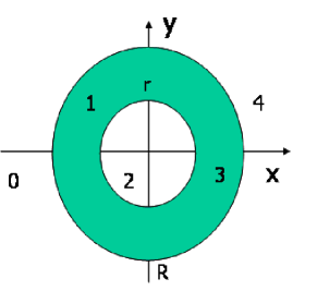
Here, space is divided into areas in which the potentials of the electron are analytic functions. The model potential is presented in figure 7. Therein, a pore is restricted by a rectangular barrier of in the form of a ring with an outer radius and inner radius ().
In the model b), the potential is as follows:
| (4) |
Such a model resembles the model of cylindrical tube [model a)] with the sole difference being that in this case its cross section is an ellipse. Comparison of (3) and (4) shows that the short semi-axes of ellipses, that restricts the hollow along the axis, coincides with the radii in model a). Large semi-axes of a size and are oriented along the axis.
We analyze the manifestation of resonant tunneling in both models. Herein, solutions of a time-independent Schrodinger equation are of the form:
| (5) |
Here, as well as above, , while index coincides with the notations of the ranges in figure 7. Thus, , , , where . The presence of and in the argument of wave function shows the two-dimensionality of the problem.
Let the electron with energy be moving from left to right along the axis. Herein, the passage through the barrier is possible only due to tunneling. In the present case, the barrier can be considered as a set of one-dimensional barriers for fixed values of . Geometric sizes of the barrier are varied depending on the specific value of . Hence, for example, in model a) at , the barrier is the thinnest, , while the size of the hollow is maximum, . In the second limiting case, at , two opposite barriers interflow and their overall thickness becomes equal to , while the hollow thickness becomes zero. In general, a traveling electron parallel to , for a fixed will be reflected from barriers at an angle different from . The larger is the smaller is the angle. Below, we restrict the analysis of tunneling in the area to no more than the neighborhood of 0.01% of the pore size along relatively to . (As will be seen, the neighborhood plays a key role in tunneling in these models). In this case the reflection angle practically equals .
The tunneling probability of a homogeneous flow of electron through the left-hand barrier into a hollow of nanoparticle is , while the total probability is determined through the integral by from 0 up to of this characteristic. Here, is the amplitude of an incident wave, while is the amplitude of the wave that has transmitted this barrier. These amplitudes may be derived from the system of eight linear equations in respect to , , , , , , , , following from the continuity condition of wave functions and their derivatives in any point, including the points of potential discontinuity. At matching together the wave functions and in the point , which is common for the regions 0 and 1 (it is the root with minus sign of the equation ), we shall get the following:
| (6) |
Similarly, matching together the wave functions and in the point (it is the root with minus sign of the equation ) yields the equation:
| (7) |
Similarly, for the points and , and and , we shall get corresponding equations:
| (8) |
| (9) |
where , while .
Continuity of the first derivatives in those same points yields still four equations:
| (10) |
| (11) |
| (12) |
| (13) |
Within the system of eight homogeneous linear equations (6)–(13) there are nine unknown quantities. However, having divided all the equations into we get a system of non-uniform equations with eight unknown quantities, including , which is connected with the tunneling probability into the hollow.
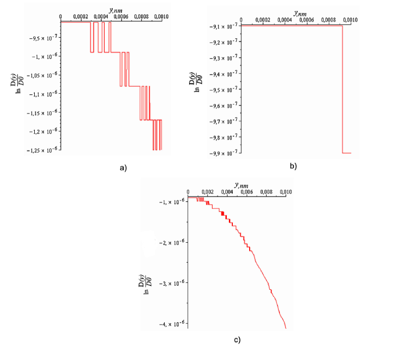
Calculations of the tunneling probability were carried out using the program Maple-13 with the parameters, eV, eV, eV, nm, nm, and semiaxis of the ellipse . The obtained results are shown in figure 8 in the form , where . Figures 8 (a), (b), show in both models in the same range of , and in figure 8 (c), the dependence in the model (b) in a wider range of . In such range in the model a), has a similar form but with less marked nonmonotonicities. Due to a large range change of , its real form is somewhat garbled by the applied Maple-13 spline. Nevertheless, even this form allows us to observe the manifestations of resonant tunneling in the models.
4 Discussion of results. Conclusions
The obtained dependencies (see figure 8) are generally of decreasing character with a set of repeating plateaus.
The decrease of tunneling probability with an increase is apparent. For any fixed it corresponds to the one-dimensional eigenvalue problem with two identical square barriers. The increase of parameter in our case causes the widening of the barriers and at the same time the narrowing of the hollow. It is known that in case of tunneling through a single barrier, the value of tunneling, similarly to our problem, decreases but this dependence does not have plateaus, which we relate to the resonant tunneling.
Let us consider the virtual states of an electron in a hollow, i.e., between two barriers. In order to qualitatively comprehend the obtained behavior of the tunneling probability, it is sufficient to employ the results of a quantum-mechanical problem of a particle in infinitely deep square well. It is well known that here the energy spectrum of a particle is a set of discrete levels ( is the mass of a particle, is the principal quantum number, ). In our case, the dependence of the well width on (and consequently ), causes the observed behavior of the tunneling probability. Compare the behavior of the ground states for two types of the pore cross section, i.e. the circular and more general elliptic one extended along . In the first case, , and in the second case , ( is the semi-axis of an ellipse). It can be seen that upon the axis, i.e., at , these levels coincide. However, the change causes a more rapid rise of position of the level in comparison with the growth of . Within the limit , does not depend on , i.e., this will be a level it ‘‘degenerates’’ by . In a general case, a step-by-step transition is accompanied by the appearance of closely positioned levels.
As noted above, at , the values coincide for both models. In the present case, is nonzero. It means that the energy of the incident electron differs from the virtual levels. Suppose that is between the virtual levels and . Increasing y (which is accompanied by narrowing the cavity) the virtual levels rise on the energy scale. In model a) the -th level with coincides with energy of the incident electron. As a result, there is a sharp drop , i.e. the resonant tunneling effect. A similar behavior of is observed in the case b), but for at . The difference between these values is connected with the fact that the hollow thickness in the model a) changes more rapidly with the change of than in the model b). A further increase of , for example, in the model a) is accompanied by resonant tunneling due to the levels at for up to its value . At 0.0006, the next virtual level, , coincides with energy of the incident electron. Further, the non-monotonous series of follows up to at which the next virtual level, , coincides with and so on.
The main conclusion of the paper consists in stating that the degree of the electron tunneling into the hollow is determined both by the geometry of the pore and by the energy of the bombarding electron.
The obtained results may be represented alternatively. Let us consider a homogeneous flow parallel to the axis of monochromatic electrons. In the range of where virtual states coincide or are close to the energy of bombarding electrons, their contribution in tunneling into hollow is either altogether absent or just minimal. A more real case is the flow of electrons with some distribution by energy. Assume that this is Gaussian-type distribution with a maximum at . Even if coincides with virtual level, there are the energies from the ‘‘tails’’ of the Gaussian that do not coincide with this level. Exactly these electrons ensure the tunneling. However, since the number of such electrons according to the Gaussian distribution is low, their contribution into tunneling will be negligible. In other words, a more real picture being taken into account does not change the qualitative conclusions obtained earlier.
Herein above we have focused on the maximum tunneling taking place at in case of a single barrier. The presence of the second identical potential barrier and hence a possible resonant tunneling, somewhat changes this statement. In the case of geometric parameters of the pore, such that at , its virtual levels coincide with the energy of the electron, this electron does not provide any contribution into the tunneling. The tunneling is realized by electrons that are more distant from and their energies do not coincide with the virtual levels. Thus, due to a larger thickness of barriers in comparison with the case, the degree of tunneling will be much lower. However, suffice it to change the energy of the electrons so that it does not coincide with the values of virtual states in the region , then the degree of tunneling will abruptly grow. On the other hand, the degree of tunneling may be essentially different for the electrons with the same energy depending on the geometry of the pores. In other words, the degree of tunneling is not much effected by the energy of electrons or by the geometry of pores, but rather by their interrelation. Thus, the above mentioned result of the paper [7] concerning the maximum tunneling in 9-nm pores in comparison with the 5, 11, the 14-nm pores may be caused by the energy bombarding electrons which least of all coincides with their virtual states.
The obtained results make it possible to propose the impedance model of the investigated mechanisms presented in figure 9 (a). Here is the resistance of electrolyte, is a relaxation resistance of the low-resistance phase and is its chemical capacity (chemical capacity is the ratio of carrier concentration n and Fermi level , [14]). Due to quantization of an energy spectrum in nanoparticles, the chemical capacity is transformed into the quantum capacity [12], and it noticeably effects the transport processes [15]. This effect should be expected only in nanoscale objects because in this case only the quantum capacity can disconnect the circuit R3-C3 (figure 7 (b)), i.e., the DC-mode.
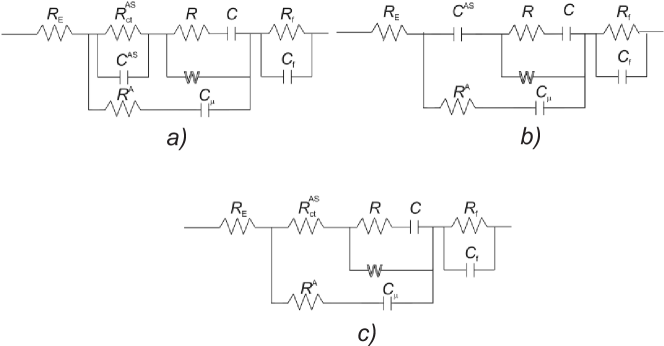
The branched circuit produces a charge transport through the barrier and – through a barrier , which divides silicon dioxide and electrolyte. The Rendls-Ershler circuit [16] produces the lithium cations transport from electrolyte into the structural channels SiO2.
According to the results of theoretical calculations it is obvious that (as well as ) depends on the particle size. Therefore, at maximum and minimum value , the equivalent circuit 9 (a) transforms into the circuits 9 (b) and 9 (c) (see figure 9). It is easy to see that the circuit 9 (b) (figure 9) is capacitive. It well describes the impedance behavior at the electron tunneling blockade into the nanoparticle SiO2 (figure 4, curve 1). The circuit 9c corresponds to deblocking the electron tunneling and to the formation of two-phase state. Results of the proposed model well agree with a package of experimental data: Kramers-Kronig test does not exceed , and the frequency dependencies of ordinary difference are of completely random character. According to the computer parametric identification (figure 10), the difference between experimental and model curves does not exceed 5%.
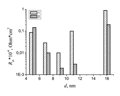
Figure 10 shows an essential dependence of the parameter on the particle size. Its sharp minimum at nm coincides with the anomaly at this value. Here is another interesting fact. Intercalated lithium into nanoparticles of various sizes (excluding very small ones) increases the charge transport.
It should be noted that the absence of diffusion control in this case and, as a consequence, the minimum content of the diffusion resistance in the total resistance of a system, is extremely important to practical application of the 9-nm particles in the current-generating process
with a horizontal discharge curve at . By contrast, another situation for the 5-nm particles (obviously, for the 16-nm particles as well) is observed – the positive charged lithium is screened by electrons, injected from contact to a conductive agent. Such an effect (obviously, possible only for nanoscale objects) may be defined as sub-Faraday or pseudo-Faraday discharge with the expected hypercapacity. Actually, at discharge of a galvanic cell with electrodes on the base of both the 5-nm and 16-nm silicon dioxide, the horizontal plots in voltage-time characteristics are absent. It testifies to the process without the 1-st type of phase transition. Results of the potentiometric measurements do not allow us to claim the prevalence of the diffusion control over the kinetic one. At least in the range of 2.94–1.85 V, the dynamic current-voltage characteristic is close to ideal polarizability. The calculated specific capacity of ‘‘a condenser regime’’ in a given electric voltage range for nanocomposites on the basis of the 5 nm silicon dioxide was 1075 F/g, and for the 16 nm one it was 2034 F/g. Taking into account the active surface area, differential capacitance reaches the record value 256 and 2400 F/cm2, accordingly. The latter value exceeds the known maximum value of the differential pseudo-capacitance by about five times [17]. As in the ideal polarizability case, the multifold charge-discharge cycles are possible here. This emphasizes the importance of the above considered nanomaterials to the technology of electrochemical storage with the high cycling. A similar conclusion is less obvious for the 11-nm nanosize titanium dioxide. Obviously, faraday and pseudo-Faraday processes co-exist here.
5 Conclusions
-
1.
The nanosize silicon dioxide with the Li+-intercalated current-generating reactions in it is suitable for technology of electrical storage with the essentially higher specific capacities and energy than in the traditional lithium current sources.
-
2.
Processes in the materials depending on size of nanoparticles can be accompanied by the formation or a two-phase state, or a pseudo-Faraday process with great differential capacitance. The reason for such a process is quantum-mechanical effect of interference blockade of the electronic tunneling into the nonmetallic nanoparticle. However, a mixed mechanism of current-generating is not excluded.
-
3.
Minimization of diffusion resistance in the nanosize silicon dioxide particles promotes the achievement of high capacities.
-
4.
The phenomenon of current-generating process in nanostructured systems is analyzed on the basis of quantum mechanical tunneling. The geometric and energy parameters, that simulate the nanostructure, entail the different structure of the electron virtual states. The efficiency of tunneling nontrivially depends on the relation between these states and the energy of electrons bombarding the nanostructure. Thus, the tunneling efficiency is a non-monotonous function on the electron energy.
References
-
[1]
Shao-Horn Y., Osmialowski S., Horn Q.C.,
J. Electrochem. Soc., 2002., 149, No. 11., A1499–A1502;
doi:10.1149/1.1513558. -
[2]
Quintin M., Devos O., Delville M.H.,
Electrochim. Acta., 2006, 51, 6426–6434;
doi:10.1016/j.electacta.2006.04.027. - [3] Brandt K. A critical review of rechargeable lithium battery technology. – In: Proc. 12-th Intern. seminar on primary and secondary battery technology and application., Deerfield Beach, USA, 1995.
- [4] Wells A.F., Structural Inorganic Chemistry. 5-th ed. Oxford University Press, Oxford, 1984.
- [5] Julien C.M., Mater. Sci. Eng. R, 2003, 40, No. 2, 47–102; doi:10.1016/S0927-796X(02)00104-3.
- [6] Kwon C.W., Hwang S.J., Poquet A., Treuil N., Campet G., Portier J., Choy J.H. – In: New trends in intercalation compounds for energy storage. Series Mathematics, Physics and Chemistry, 2002, 61, 439–446.
- [7] Myronyuk I.F., Lobanov V.V., Ostafijchuk B. K, Mandzuk V.I. Grygorchak I. I., Yablon’ L.S., Phys. Chem. Sol. State, 2001, 2, No. 4, 653–660 (in Ukrainian).
- [8] Venhryn B.Ya., Grygorchak I.I., Kulyk Yu.O., Opt. Appl., 2008, XXXVIII, No. 1, 119–125.
- [9] Thompson A.G., Physica B+C, 1980, 99B, No. 4, 100–105; doi:10.1016/0378-4363(80)90216-8.
- [10] Modern battery technology. Ed. Tuck C.D.S., Ellis Horwook, New York, 1991.
- [11] Golant E.I., Pashkovskii A.B., Semiconductors, 2002, 36, 311–318; doi:10.1134/1.1461409.
- [12] Bohm D., Quantum Theory. Prentice Hall, New York, 1952.
- [13] Davies John H., The Physics of Low-Dimensional Semiconductors: An Introduction. Cambridge University Press, 1998.
- [14] Mora-Sero I., Bisquert J., Nano Lett., 2006, 6, No. 4, 640–650; doi:10.1021/nl052295q.
- [15] Luryi S., Appl. Phys. Lett., 1988., 52, No. 8, 501–503; doi:10.1063/1.99649.
- [16] Stojnov Z.B. et al., An Electrochemical Impedance. Nauka, Moscow, 1991 (in Russian).
- [17] Conway B.E., Electrochemical Supercapacitors. Plenum Publ., New York, 1999.
Квантово-механiчне явище тунелювання i ефективнiсть фарадеєвського струмоутворення в пористих наноструктурах Б.А. Лукiянець, Д.В. Матулка, I.I. Григорчак \addressНацiональний унiверситет “Львiвська полiтехнiка”, вул. С. Бандери, 12, 79013 Львiв, Україна