Thermal conductivity of mass-graded graphene flakes
Abstract
In this letter we study thermal conduction in mass-graded graphene flakes by nonequilibrium molecular dynamics simulations. It is found that mass-graded graphene flakes reveal no thermal rectification effect in thermal conduction process. The dependence of thermal conductivity upon the heat flux and the mass gradient are studied to confirm the generality of the result.The mechanism leading to the absence of thermal rectification effect is also discussed.
pacs:
65.80.Ckpacs:
66.70.-fpacs:
81.05.UeThermal properties of graphene Nonelectronic thermal conduction and heat-pulse propagation in solids Graphene Graphene, a single layer of carbon atoms in a honeycomb lattice with sp2 bonds, has attracted much interest due to its novel properties[1, 2]. It reveals superior high thermal conductivity up to 2500-5000 W/mK at room temperature[3, 4]. Thus it has been considered as a promising candidate for various kinds of thermal devices, such as thermal rectifiers. Thermal rectification is a phenomenon that the heat flux runs preferentially along one direction and inferiorly along the opposite direction[5, 6, 7, 8]. Researchers have proposed several different graphene based thermal rectifiers by introducing asymmetric shapes in molecular dynamics simulations[9, 10, 11, 12]. The preferred direction of the heat flux is observed from the wide to the narrow region.
Recently a new procedure is considered by Chang et al. in carbon and boron nitride nanotubes[13]. They introduce mass gradient along the axis of the nanotubes by covering external platinum compound on the nanotubes. Since the platinum compound is almost thermal insulating and the sp2 bonds in nanotubes are much stronger than the bonds between the fused external molecules, so Chang et al. idealize their procedure as changing the mass of atoms in thermal conduction. Higher thermal conductivity is observed when the heat flux runs from the heavy to the light atoms and the rectification ratio is about 2-7%. Similar thermal rectification effect is also observed in 1D mass-graded Fermi-Pasta-Ulam (FPU) chain and 1D single carbon chain[8, 14]. Influence of anharmonicity is surmised to explain the rectification effect. Later Alaghemandi et al. have studied thermal conductivity of mass-graded carbon nanotubes by RNEMD (reverse nonequilibrium molecular dynamics) simulations[15, 16, 17]. In their simulations, the atomic mass of carbon atoms is gradually increased from 12 to 300 along the axis of the tube. The carbon atoms interact via harmonic radial, angular and torsion potentials with constant force constants. Much higher thermal conductivity is observed when the heat flux runs from the light to the heavy atoms and the rectification ratio is about 20-50%. The rectification effect is explained as the strong coupling between the longitudinal and transverse modes in the carbon nanotubes[17].
Since the structure and thermal property of graphene are similar to carbon nanotube, one might expect the similar thermal rectification in mass-graded graphene. However in this letter, we demonstrate that mass-graded graphene flakes reveal no thermal rectification effect by NEMD (nonequilibrium molecular dynamics) simulations. Here we refer to graphene flakes with infinite width in thermal conduction process. Since the geometric deformation along the width is avoided by using the periodic boundary condition, it is used to approach the simulation condition with infinite width. Different heat flux and mass gradient are investigated to confirm the generality of the result. Furthermore, we also study the finite wide graphene flakes by using free boundary condition. A weak rectification effect is observed and the rectification ratio is evidently approaching zero by increasing the width. Based upon the numerical results, we discuss the mechanism leading to the absence of thermal rectification.
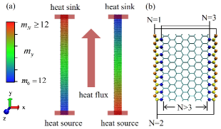
We carry out the simulations in two graphene flakes with zig-zag edges along the x-axis and armchair edges along the y-axis. The graphene flakes are shown in Fig. 1(a). They are both 288 Å long and 20 Å wide. The heat sources and heat sinks are covered by red boxes. The outmost edges of the heat sources/sinks are frozen. It corresponds to fixed boundary conditions in the y-axis. Opposite mass gradients are implemented in the two graphene flakes. The atomic mass of the carbon atoms between the heat sources and the heat sinks along the y-axis is set as:
| (1) |
Here , . We label the first graphene flake in Fig. 1(a) as the graphene flake. Its atomic mass varies from to . Similarly we label the second one as the graphene flake. The heat flux runs along the graphene flake is equivalent to the reversed heat flux runs along the graphene flake. Thermal conduction process is investigated by imposing the same heat flux along the two graphene flakes. It is much more convenient later to compare the temperature profiles since the heat sources and heat sinks are in the same direction. When using periodic boundary condition along the x-axis, the edge atoms and the inside atoms are the same. However when using free boundary condition along the x-axis, the edge atoms would be less bound than the inside atoms. They have different geometric surroundings. It is shown in Fig. 1(b), the edge atoms are labelled as , 2, 3 and the inside atoms are labeled as . We use the adaptive intermolecular reactive empirical bond-order (AIREBO) potential[18] as implemented in the LAMMPS[19] code in the simulations. The REBO term simulates the anharmonic valence-bonded C-C interactions in graphene. The bond energy consists of a repulsive and attractive part:
| (2) |
Here ,, is the distance between the carbon atoms, is a function of the local coordination and bond angles for the th and th atoms, , , , are parameters which have been fitted according to carbon systems and can be found in the original paper[18]. Equations of motions are integrated with velocity Verlet algorithm with the minimum timestep fs.
First we study the thermal conduction of the two graphene flakes by using periodic boundary condition along the x-axis. The graphene flakes are equilibrated at a constant temperature K in the Nose-Hoover thermostat by 0.75 ns. After that the heat flux is imposed. It is realized by the energy and momentum conserving velocity rescaling algorithm developed by Jude and Jullien[20, 21, 22]. By rescaling atomic velocities at each time step , specific amount of kinetic energy is added in the heat source and removed in the heat sink respectively. The heat flux can be calculated by . We divide the graphene flakes by several 8 Å long slabs to obtain the temperature profiles. The local temperature in each slab is calculated from the averaged kinetic energy of the carbon atoms. We average the temperature profiles over 100 ps after the heat flux is imposed. The nonequilibrium simulation process covers 3 ns. Thermal conductivity is obtained by the Fourier’s law:
| (3) |
Here is the heat flux, is the cross section of the heat transfer defined by the width and thickness of the graphene flakes (1.4 Å is considered as the thickness), is the temperature gradient. The reported data represents the steady state over the last 1000 ps. The standard error of statistical uncertainties is within 5%. Similarly, in order to understand the geometric deformation in thermal conduction, the bond length () profiles are also obtained. The bond length describes the average distance of a carbon atom between its three neighbors.
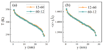
In Fig. 2(a) we show the typical temperature profiles of the two graphene flakes. and eV/ps are implemented. The two temperature profiles are the same which indicates the heat flux runs equivalently without preferred direction. Their thermal conductivities W/mK are the same. Thus unlike mass-graded carbon nanotubes, mass-graded graphene flakes reveal no obvious thermal rectification effect even a large mass gradient is implemented.
In Fig. 2(b) we show the associated bond length profiles. There is no obvious difference between the two profiles. It indicates the geometric deformation is also insensitive to the direction of the mass gradient. Furthermore, a positive thermal expansion is observed along the longitudinal direction. The bond lengths near the heat sources are larger than those near the heat sinks. The average bond length of all the carbon atoms is still equal to 1.4 Å because the widths of the graphene flakes are unchanged by using periodic boundary condition in the x-axis.
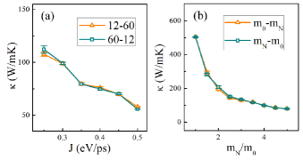
In order to confirm there is no thermal rectification effect, different heat flux and mass gradient are applied. First we keep the mass gradient unchanged and vary the heat flux from 0.25 to 0.5 eV/ps. In Fig. 3(a) we show the dependence of thermal conductivity upon the heat flux. If the heat flux eV/ps, the difference of thermal conductivities between the two graphene flakes is less than 2%. The effect of thermal fluctuation is stronger for small heat flux value, so it would lower the computation certainty. Thus for eV/ps, the difference of thermal conductivities becomes 4.6% which is still very small. The result suggests there is no thermal rectification effect by varying the heat flux. It is different from mass-graded carbon nanotubes. Their thermal conductivity difference would be as large as 20-50%[16, 17].
Second we keep the heat flux eV/ps unchanged and vary the mass gradient from 1 to 5. In Fig. 3(b) we show the dependence of thermal conductivity upon the mass gradient. The thermal conductivity difference is still within 5%. The result suggests there is no thermal rectification effect by varying the mass gradient. It is also different from mass-graded carbon nanotubes. Their thermal conductivity difference increases with the mass gradient[16, 17]. Furthermore, the thermal conductivity of the graphene flakes decrease dramatically with the mass gradient. If there is no mass gradient, the thermal conductivity is 505 W/mK. When the mass gradient is implemented, it is reduced to 75 W/mK. It is only about 15% of the original value. So it provides a possible route to tune the thermal behavior of graphene by modulating the mass gradient. Two methods could be considered to implement the mass gradient. One is to load external heavy and thermal insulating molecules. It has been widely accepted as an idealized method to implement mass gradient in carbon nanotubes[13, 15, 16]. The other one is to use different ratio of isotope substitutions. Simulations of carbon nanotubes[23] and graphene[24, 25] of isotope defects have already predicted the thermal conductivity reduction. The method is demonstrated possible in experiment by chemical vapor deposition growth of graphene on metal[26].
To explain why rectification effect is not observed, we need to consider the influence of asymmetric shape, anharmonicity and mode coupling. They are the underlying mechanisms involved in thermal rectification. It is known that different influence of those attributes in the physical properties of 1D single chains and quasi-1D nanotubes, raises quite different rectification effect[16, 17]. Thus it is also interesting to understand how those attributes contribute in mass-graded graphene which is a 2D system.
First we consider the influence of asymmetric shape. The geometric deformation along the width is avoided by using the periodic boundary condition in the x-axis. It is used to approach the simulation condition that the infinite width is considered. As shown in Fig. 2(b), the geometric deformations are the same in both graphene flakes. So the geometric deformations bring no rectification effect. Later we shall discuss the case when the finite width is considered.
Second we consider the influence of anharmonicity. Low-frequency modes contributing predominantly to thermal conduction can be generated when the anharmonic part of the FPU potential is excited. Thus heat flux runs preferentially from the heavy to the light atoms in 1D mass-graded Fermi-Pasta-Ulam (FPU) chain[8]. To explain why such effect is not observed in mass-graded graphene, we postulate that in carbon systems anharmonicity is insufficient to bring an obvious rectification. For example, in 1D carbon chain, only by implementing an extremely large mass gradient (32), such rectification effect might be confirmed[14]. Thus for the mass gradients used in our simulations (5), the influence of anharmonicity would be too weak to be detected. Furthermore, thermal conductivity is dramatically decreased with the mass gradient. So the application of the extremely large mass gradient might be very limited.
Third we consider the influence of mode coupling. The coupling between the longitudinal and transverse modes is more efficient when the light atoms are placed at high temperature regions. Thus heat flux runs preferentially from the light to the heavy atoms in mass-graded carbon nanotubes. However it is also known that the mode coupling within a 2D plane is much less strong than mode coupling in a bend topology, such as quasi-1D nanotubes. Unlike mass-graded carbon nanotubes, the associated rectification effect is very small in mass-graded graphene flakes which belong to the 2D system[17]. So it is difficult to distinguish the effect of mode coupling from the thermal fluctuation in the MD simulations.
By using periodic boundary condition in the x-axis, it corresponds to the simulation condition that the infinite width is imitated. In order to understand thermal conduction in finite wide mass-graded graphene flakes, free boundary condition in the x-axis is considered. Geometric deformation in the x-axis is possible in this case. and eV/ps are implemented.
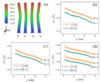
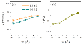
In Fig. 4(a) we show the thermal curvature in the graphene flake. It is incessantly twisted in the thermal conduction process. Similar thermal curvature is also observed in the graphene flake. Thermal conductivity of the graphene flake is 67.8 W/mK. Thermal conductivity of the graphene flake is 61.4 W/mK. They are smaller than 75 W/mK in Fig. 2 where periodic boundary condition is used. Similar reduction of thermal conductivity caused by geometric deformation has been observed in graphene and carbon nanotube recently[27, 28].
In Fig. 4(b)-(d) we show the bond length profiles in the and graphene flakes. As shown in Fig. 1(b), when using free boundary condition, the edge atoms are less bound with different geometric surroundings. So their bond lengths are different from the inside atoms. The bond lengths of the edges atoms are much smaller than 1.4 Å which corresponds to negative thermal expansion along the width. Meanwhile the bond lengths of the edge atoms and the inside atoms are barely affected. It indicates the negative thermal expansion occurs mostly along the edge. The transverse negative thermal expansion in graphene has already been observed in experiment and simulation[29, 30].
The bond length profiles in Fig. 4(b)-(d) also indicate asymmetric geometric deformation occurs. The bond lengths in the graphene flake is smaller than in the graphene flake. It is responsible for the observed weak thermal rectification effect. The thermal rectification ratio is defined as[13, 15, 16, 17]:
| (4) |
Thus for the and graphene flakes, the rectification ratio is . The negative sign of indicates heat flux runs preferentially from the light to the heavy atoms. It is similar to mass-graded carbon nanotubes[15, 16, 17].
In order to understand the influence of finite width, different width is considered. Here we only choose the graphene flakes with two zig-zag edges along the x-axis. Thus the chiralities of the graphene flakes is unchanged. Free boundary condition in the x-axis is applied. and eV/ps are implemented. In Fig. 5(a) we show the dependence of thermal conductivity upon the width. The result indicates higher thermal conductivity is obtained by placing the heat source near the light atoms. In Fig. 5(b) we show the dependence of the rectification ratio upon the width. We use the average value of in Fig. 5(a) to obtain . The rectification ratio is very small and evidently approaching 0 by increasing the width. The result suggests the thermal rectification effect might be very weak and cannot be observed in real application because the width of graphene flake used in experiment is quantitatively large.
In summary, mass gradients in graphene flakes can not lead to thermal rectification effect if the finite width effect is avoided by using periodic boundary condition. Different heat flux and mass gradient are considered to confirm the result. Meanwhile a weak rectification effect is observed by using free boundary condition. However the rectification ratio is evidently approaching zero by increasing the width. The result implies that geometric deformation, anharmonicity and mode coupling in mass-graded graphene are insufficient to bring rectification effect. Additionally, mass gradient is demonstrated as an effective way in tuning the thermal behavior of graphene. We hope our work shed light on understanding the thermal conduction in mass-graded carbon systems and designing graphene based thermal devices.
Acknowledgements.
We thank Jiao Wang, Yong Zhang and Dahai He for helpful discussion and preparing of the manuscript. This work was supported by National Natural Science Foundation of China(#10775115 and #10925525).References
- [1] \NameGEIM A. K. and NOVOSELOV K. S. \REVIEWNat. Mater.62007183.
- [2] \NameGEIM A. K. \REVIEWScience.32420091530.
- [3] \NameBALANDIN A. A., GHOSH S., BAO W., CALIZO I., TEWELDEBRHAN D., MIAO F. and LAU C. N. \REVIEWNano Lett.82008902.
- [4] \NameCAI W., MOORE A L., ZHU Y., LI X., CHEN S., SHI L. and RUOFF R. S. \REVIEWNano Lett.1020101645.
- [5] \NameCASATI G. \REVIEWNat. Nanotech.2200723.
- [6] \NameROBERT N. A. and WALKE D. G. \REVIEWInt. J. Therm. Sci.502011648.
- [7] \NameHU B., YANG L. and ZHANG Y. \REVIEWPhys. Rev. Lett.972006124302.
- [8] \NameYANG N., LI N., WANG L. and LI B. \REVIEWPhys. Rev. B.762007023301.
- [9] \NameHU J., RUAN X. and CHEN Y. P. \REVIEWNano Lett.920092730.
- [10] \NameYANG N., ZHANG G. and LI B. \REVIEWAppl. Phys. Lett.952009033107.
- [11] \NameOUYANG T., CHEN Y., XIE Y., WEI. X. L., YANG K., YANG P. and ZHONG J. \REVIEWPhys. Rev. B.822010245403.
- [12] \NameJIANG J. W., WANG J. S. and LI B. \REVIEWEurophys. Lett.89201046005.
- [13] \NameCHANG C. W., OKAWA D., MAJUMDAR A. and ZETTL A. \REVIEWScience.31420061121.
- [14] \NameZENG N. and WANG J. S. \REVIEWPhys. Rev. B.782008024305.
- [15] \NameALAGHEMANDI M., ALGAER E., BOHM M. C. and MULLER-PLATH F. \REVIEWNanotechnology.202009115704.
- [16] \NameALAGHEMANDI M., LEROY F., ALGAER E., BOHM M. C. and MULLER-PLATH F. \REVIEWNanotechnology.212010075704.
- [17] \NameALAGHEMANDI M., LEROY F., MULLER-PLATH F. and BOHM M. C. \REVIEWPhys. Rev. B.812010125410.
- [18] \NameSTUART S. T., ALAN B. T. and HARRISON J. A. \REVIEWJ Chem. Phys.11220006472.
- [19] \NamePLIMPTON S. \REVIEWJ. Comput. Phys.11719951.
- [20] \NameJUND P. and JULLIEN R. \REVIEWPhys. Rev. B.59199913707.
- [21] \NameLIANG Z. and TSAI H. L. \REVIEWPhys. Rev. E.832011041602.
- [22] \NameHU M., GOICOCHEA J. V. MICHEL B. and POULIKAKOS D. \REVIEWAppl. Phys. Lett.952009151903.
- [23] \NameZHANG G. and LI B. \REVIEWJ. Chem. Phys.1232005114714.
- [24] \NameOUYANG T., CHEN Y. P., YANG K. K. and ZHONG J. X. \REVIEWEurophys. Lett.88200928002.
- [25] \NameBALASUBRAMANIAN G., PURI I. K., BOHM M. C. and LEROY F. \REVIEWNanoscale.320113714.
- [26] \NameLI X., CAI W., COLOMBO L. and RUOFF R. S. \REVIEWNano Lett.920094268.
- [27] \NameWEI N., WANG H. Q. and ZHENG J. C. \REVIEWNanotechnology.222011105705.
- [28] \NameALAGHEMANDI M., SCHULTE J., LEROY F., MULLER-PLATHE F. and BOHM M. C. \REVIEWJ. Comput. Chem.322011121.
- [29] \NameBAO W., MIAO F., CHEN Z., ZHANG H., JANG W., DAMES C. and LAU C. N. \REVIEWNat. Nanotechnol.42009562.
- [30] \NameJIANG J. W., WANG J. S. and LI B. \REVIEWPhys. Rev. B.802009205429.