Ripple edge engineering of graphene nanoribbons
Abstract
It is now possible to produce graphene nanoribbons (GNRs) with atomically defined widths. GNRs offer many opportunities for electronic devices and composites, if it is possible to establish the link between edge structure and functionalisation, and resultant GNR properties. Switching hydrogen edge termination to larger more complex functional groups such as hydroxyls or thiols induces strain at the ribbon edge. However we show that this strain is then relieved via the formation of static out-of-plane ripples. The resultant ribbons have a significantly reduced Young’s Modulus which varies as a function of ribbon width, modified band gaps, as well as heterogeneous chemical reactivity along the edge. Rather than being the exception, such static edge ripples are likely on the majority of functionalized graphene ribbon edges.
pacs:
81.05.ue, 62.20.de, 81.40.Jj, 31.15.E-, 81.05.ujI Introduction
Since the start of the graphene boom in 2004 Novoselov et al. (2004), the simplistic picture of a perfect flat carbon monolayer has been refined. Notably dynamic rippling of graphene has been demonstrated via electron microscopy Meyer et al. (2007) and molecular dynamics calculations Fasolino et al. (2007), and there have been first discussions of the possibility for stable static ripples in graphene Thompson-Flagg et al. (2009); Shenoy et al. (2008). In reality graphene is not an infinite plane but is constrained by edges. Graphene nanoribbons (GNRs) have different properties from the infinite bulk material, notably they can display a finite band gap as a function of ribbon width Barone et al. (2006). In addition the physical and chemical behaviour of the one-dimensional edges will be superimposed on that of the bulk two-dimensional graphene. Graphene nanoribbons can be produced by unzipping carbon nanotubes Kosynkin et al. (2009), lithography Tapaszto et al. (2008); Fasoli et al. (2009), etching Bai et al. (2009) and controlled chemical bottum-up methods Cai et al. (2010), and offer great potential both for nanoelectronics Chen et al. (2007) and nanocomposites Su et al. (2009). Edges are an easily accessible way to chemically functionalise the graphene and hence modify its properties. We show here that careful design of graphene edges allows us to define the graphene nanoribbon properties.
The simplest way to saturate GNR edge dangling bonds is via hydrogen termination, which is the standard approach in GNR modelling Nakada et al. (1996); Wassmann et al. (2008). However other terminating heteroatoms can be imagined (e.g. N, O), and an intriguing example of this was a recent theoretical study which found F-terminated armchair GNRs to be more stable when twisted helically Gunlycke et al. (2010).
However to develop a more realistic picture of the possibilities of GNR edge chemistry, more complex termination groups have to be investigated. A good example are hydroxyl groups (OH), which as well as being bulkier than simple heteroatoms also show more complex chemical interaction between themselves. Such groups have been proposed as a way to introduce strain along the graphene edge Peng and Velasquez (2011), in order to tune GNR electronic properties such as bandgap Gui et al. (2008); Guinea et al. (2010).
However two dimensional layered materials such as graphene have alternative mechanisms for relieving edge-induced strain, namely structural deformation into the third dimension via rippling or buckling Shenoy et al. (2008).
This additional degree of freedom adds significant richness to graphene edge chemistry, which we investigate here for infinitely long armchair graphene nanoribbons (AGNRs) using the example of hydroxyl functionalisation.
In the current study we show how -OH termination of different width AGNRs modifies their structure, strain and stability. We then demonstrate the effect of such functionalisation on band gap, chemical reactivity to metal deposition, and Young’s Modulus, and generalise to other functional groups and ribbon types.
This study points the way towards “edge termination engineering” as a way to create GNRs with custom designed properties.
II Method
We performed density functional theory calculations under the local density approximation as implemented in the AIMPRO code Briddon and Jones (2000); Rayson and Briddon (2007). The calculations were carried out using supercells, fitting the charge density to plane waves within an energy cut-off of 200 Ha. Electronic level occupation was obtained using a Fermi occupation function with eV. Relativistic pseudo-potentials are generated using the Hartwingster-Goedecker-Hütter scheme Hartwigsen et al. (1998). These functions are labelled by multiple orbital symbols, where each symbol represents a Gaussian function multiplied by polynomial functions including all angular momenta up to maxima ( = 0, 1) and ( = 0, 1, 2). Following this nomenclature, the basis sets used for each atom type were (C), (H) and (O), resulting in 38 independent functions for carbon, 12 for hydrogen and 40 for oxygen. A more detailed account of the basis functions can be found elsewhere Goss et al. (2007). A Bloch sum of these functions is performed over the lattice vectors to satisfy the periodic boundary conditions of the supercell.
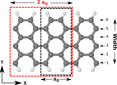
Supercell sizes have been checked and chosen to be sufficiently large (y- and z-distance between ribbons Å) to avoid interaction with neighbouring GNRs. A fine k-point grid was chosen of the form with where is the length of a fundamental unit cell along the ribbon axis in the supercell (see Fig.1), which gives energies converged to better than 10-5 Ha. For rippled GNRs the unitcell was doubled along the ribbon () to satisfy the periodic conditions of the supercells (longer period ripples using cells, were also tested but found to be less stable) . For all structures the atom positions and the lattice parameters have been fully relaxed. The definition of ribbon widths of AGNRs is given by Cervantes-Sodi et al. Cervantes-Sodi et al. (2008) and is used in the text and Fig.3 and Fig.6 (definition see Fig.1).
III Results and discussion
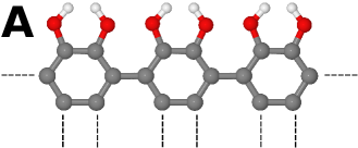
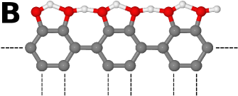
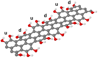
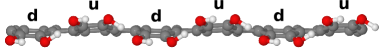
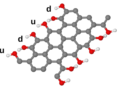
Larger functional groups on the GNR edge can introduce a range of possible inter-group interactions, including steric hindrance, Coulombic repulsion, dipole-dipole interactions and hydrogen bonding. Taking the case of hydroxyl groups we attempt to address these systematically. We have modelled fifteen different structural possibilities but focus here on three structures of hydroxylated edges for GNRs with widths from 4 to 20 (refered to hereafter as structures A, B and C). The relevant relaxed edge structures are shown in Fig.2 and associated structural parameters in Table 1.
| Structure | (Å) | (Å) | (Å) | |
| A (flat) | - | |||
| B (flat) | width 4 | / | ||
| width 20 | / | |||
| C (rippled) | width 4 | / | ||
| width 20 | / | |||
| Phenol () | - | |||
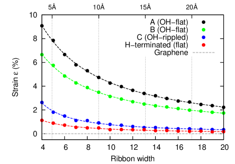
We start with structure A, symmetry constrained to lie in the plane with symmetrically paired -OH groups, removing any possibility for hydrogen bonding. Calculated bond lengths are Å and Å. This structure was recently discussed as a possible configuration for inducing strain in AGNRs Peng and Velasquez (2011). Indeed we find that it induces strains of up to 9 % for small AGNRs (see Fig.3,b). However this structure is extremely unstable. Strain along the ribbon has been calculated as follows (see also Fig.1):
with our optimized DFT (LDA) lattice parameter along the armchair direction of free standing graphene, in good agreement with experimental values of Grass et al. (2008).
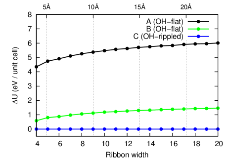
We next introduce hydrogen bonding between the hydroxyl groups by breaking the in-plane symmetry, giving the most stable planar configuration, structure B. Here Å with hydrogen forming one strong covalent bond Å and one weaker hydrogen bond Å. This new hydrogen bond lowers the system energy by typically 3.7 eV/unit cell compared to Structure A, and reduces slightly the induced strain (still up to for small AGNR compared to perfect graphene, as can be seen in Fig.3,b).
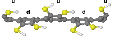
However by additionally breaking the planar symmetry we reach the energetically most stable configuration for hydroxyl terminated AGNRs, structure C. The -OH groups displace out of plane pairwise, creating a static sinosoidal ripple along the AGNR edge (see Fig.2,d,e). By displacing out of plane the structure releases up to eV/unitcell (Fig.3,a) and the strain in the ribbon is relieved (Fig.3,b), returning to values similar to hydrogen terminated AGNRs. The carbon pairs for each hexagonal ring are displaced up and down alternately (longer period oscillations tested in supercells with and at a variety of ribbon widths were found to be less stable). While stays largely unchanged at 1.36 Å, the covalent extends to Å, while the rippling allows the hydrogen bond lengths to increase to Å. These lengths are approaching our calculated bondlengths for phenol ( Å, Å, Table 1).
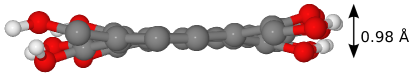
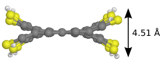
The out of plane deformation mode can be understood as an elastic response to a 1D edge line tension applied to a rigid 2D graphene sheet (our calculated Young’s Modulus for graphene is 1.08 TPa), where it is clearly energetically favourable to buckle the edge rather than stretch the whole sheet. However non-planar sheet deformation decreases the -orbital overlap, and this enthalpic driving force of graphene to remain flat localises the rippling along the ribbon edge. This can be seen in Fig.4 where the ripple amplitude increases from Å (width = 4) to Å for large ribbons (width ), and where out-of-plane displacements remain localised within Å of the graphene ribbon edge. The ripple amplitude is inversally proportional to the AGNR strain and only indirectly coupled to the width of the ribbon, consistent with a picture of a constant buckled edge length more able to dilate the graphene when its basal plane area is smaller.


No energy barrier was found between the rippled C and flat B structures, demonstrating that configuration B is a metastable maximum (see Supplementary Materialssupmat ). The energy barrier calculations can be summed to estimate the ripple inversion barrier, giving a minimum barrier of to invert one edge wave. This barrier is too high for thermal activation at room temperature, and structure C can be considered as a static edge rippling.
Thus we find that hydroxylated AGNRs will show spontaneous static edge ripples, due to an edge-strain induced out-of-plane deformation mode. As a result the strain induced by the rippled hydroxylated edge is for wide ribbons less then % (width ), and very close to that of H-terminated AGNRs of the same width ( %). We note that we found no significant interaction between the two edges of different OH-terminated AGNRs (as reflected in the total energy or strain), suggesting they are largely decoupled.
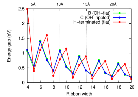
We next investigate how static ripples modify the ribbon properties, comparing structures B and C to determine the influence of rippling, and C and H-terminated ribbons to determine the influence of the hydroxyl functional group. Starting with electronic properties, we obtain good agreement between our calculated LDA band gap for flat H-terminated AGNRs and previous literature Barone et al. (2006). Bandgap is inversely proportional to ribbon width, superimposed with strong 3N periodicity. This alternation is explainable via Clar sextet theory Baldoni et al. (2008) and Fermi wavelength Ezawa (2006). The calculated band gap for structures B and C (see Fig.6,a) are almost superposed, showing that edge rippling does not appear to affect the gap for -OH termination, which is instead dominated by the choice of edge functional group. Once again we observe 3N periodicity Baldoni et al. (2008) but the difference with H-termination is not a simple phase shift of the periodicity. For () widths the bandgap is similar to the H-terminated case, but for and the difference is significant, with bandgap fluctuations of up to 50%. Thus ribbon band gap appears highly sensitive to choice of edge functional group, however the gap is not sensitive to out-of-plane edge rippling for -OH termination.
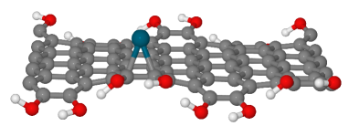
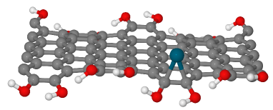
Rippling may be expected to modify the chemical reactivity of the ribbon surface, and to estimate this we calculated possible bonding sites for single Pd atom addition on a AGNR (width 10). Pd sits above C-C bond centres Suarez-Martinez et al. (2009); Lopez-Corral et al. (2010), confirmed in our calculations. In general binding nearer the ribbon edge is more stable. For rippled edges we find Pd atoms at the ribbon edge are 0.4 eV more stable in a concave “valley” site of an edge ripple than on the convex “ridge top” (see Fig.5). Indeed the concave “top” site is even 0.1 eV less stable than a flat site at the ribbon centre. We expect that with enough activation energy the Pd atoms can migrate to the edge and will sit in the valleys of the rippled edge structure. Thus the ripple-induced changes in surface curvature periodically modify the surface reactivity of the graphene, suggesting interesting changes in absorption behaviour for chemisorbed and physisorbed species, and potentially important geometric effects for metal contact deposition.
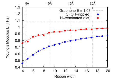
The largest change due to edge rippling we find is in AGNR mechanical behaviour. We determined Young’s Modulus () of AGNRs along their length using the approach described by Zeinalipour-Yazdi et al Zeinalipour-Yazdi and Christofides (2009). Inducing strain up to % along the ribbon the total energies have been calculated (7-points). Energy difference () vs. strain () was fitted with a quadratic function . is given by , where is the volume of the ribbon section composed of length , width taken as the H-H distance between the edges, and Å. We find for flat infinite graphene to be TPa, in good agreement with literature values ( TPaZeinalipour-Yazdi and Christofides (2009), TPaLiu et al. (2007)). However finite width H-terminated and edge-rippled OH-terminated AGNRs show significantly smaller Youngs’ Modulus (see Fig.6,b). In both cases modulus is approximately inversely proportional to ribbon width, with some non-linearity at smaller widths when edge effects start to dominate. Both edge terminations extrapolate to the ideal graphene value at infinite width (H-terminated: TPa, OH-rippled: TPa), and as expected the modulus of -H terminated AGNRs drops towards the value for cis-polyacetylene at small widths. However surprisingly, changing the edge functionalisation from -H to rippled -OH groups significantly decreases the Youngs’ Modulus of the ribbon. This reduction is a direct result of the rippling (indeed calculations for the unstable flat -OH ribbons structure B, actually show a slight increase in Youngs’ Modulus over the -H terminated case, since in this case the ribbon is under slight tension (see Supplementary Materialssupmat )). We note that as for the band gap, a periodicity of can be seen in the values of reflecting variations in C-C bonding with width. These changes in as a function of both ribbon width, and edge termination, will be critical in graphene nanocomposite design. Modifying ribbon edge functionalisation is an obvious way to chemically bind nanoribbons into a host polymer matrix, but these results show that changing the functionalisation groups can decrease the Young’s Modulus of the nanoribbon itself as much as 40 %.
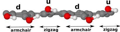
In order to determine how general the static edge rippling effect is, we next examined other chiralities. Hydroxylated zig-zag GNRs (ZGNRs) do not exhibit out-of-plane edge rippling, due to the larger spacing between edge C atoms (2.44 Å) which results in sufficient spacing between the -OH groups to keep edge strain below %. Indeed, in principle edge tension might be expected to induce rippling within the ribbon centre, the inverse effect of AGNRs, however the rigidity of the graphene sheet precludes this. Note however this does not preclude rippling in ZGNRs for larger functional groups. Calculations for hydroxylated chiral edges show an intermediate effect, with localised edge rippling around armchair-like sections which rapidly decays in zig-zag sections of the edge (see Fig.7). Thus these results show that the majority of GNR edge types, when hydroxylated, will exhibit static rippling.
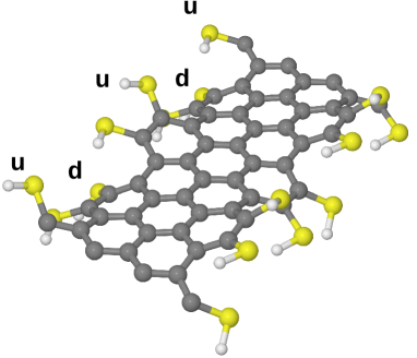
We also examined the dependence of static edge rippling in AGNRs on functional group, replacing -OH with -F, -Cl, and -SH. In all cases the ribbons exhibited the same periodic edge rippling as the hydroxylated edges (see Fig.8 and Supplementary Materialssupmat ). Thus a key finding of this study is that flat GNR edges, as exemplified by hydrogen termination, appears to be the exception rather than the rule. The majority of graphene nanoribbon chiralities and functionalisations we have examined undergo spontaneous out-of-plane static rippling.
IV Conclusions
This fundamental study provides a first picture of underlying physics for adding complex functional groups to graphene edges and in particular AGNRs. Hydroxyl groups do not induce large strain in GNRs, since the strain is compensated by static ripple formation along the ribbon edge. Such ripples form in the majority of ribbon chiralities and functional groups we have examined, suggesting flat ribbon edges as observed for hydrogenation may be the exception. This also seems to rule out edge functional groups as a simple way of inducing large strains in the graphene basal plane. For the first time we calculate Young’s Modulus for infinite AGNRs with -H and -OH terminations, and show that edge ripples can drastically modify the mechanical properties and chemical reactivity of the ribbon. We believe this could have a big impact on engineering devices and composites with embedded GNRs. We find that the band gap is not sensitive to static edge rippling for -OH termination, but can change by up to 50 % depending on choice of edge functional group.
There are various ways to match a 1D line tension along a ribbon edge against a 2D surface strain in the basal plane. In the case of graphene, with a Young’s Modulus of 1.08 TPa, the in-plane resistance to tension is high and edge compression is the energetically favoured solution, resulting in static ripple formation at the edge. At the same time there is an energetic cost associated with rippling induced disruption of the graphene -network, and hence the ripples remain localised near to the ribbon edge, reducing the effective flat basal plane width of the ribbon. In the case of chiral and aperiodic edges, static edge rippling is likely to lead to weak localisation and a decrease in the intravalley scattering length, consistent with experimental observations in graphene flakes Tikhonenko et al. (2008).
The discussion thus far concerns free-standing graphene. On substrates the modulating height of the hydroxylated edge ripples will result in periodic modulation in the graphene-substrate spacing and hence the substrate-induced potential felt by the nanoribbon, increasing electronic localisation effects. Variation in graphene-substrate spacing at the ribbon edge could also facilitate impurity intercalation beneath the graphene. Finally we note that this static edge rippling behaviour is a fundamental response of a 2D layered system to 1D edge strain, and as such is also likely to also be of importance in the range of new monolayer materials under development such as BN, MoS2 and NiTe2 Coleman et al. (2011). Strain compensation through rippling is also likely to be important at other graphene interfaces such as grain boundaries.
Acknowledgements.
PW, CPE and VVI thank the NANOSIM-GRAPHENE project n∘ANR-09-NANO-016-01 funded by the French National Agency (ANR) in the frame of its 2009 programme in Nanosciences, Nanotechnologies & Nanosystems (P3N2009). We thank the CCIPL, where some of these calculations were performed. We thank COST Project MP0901 NanoTP for support.References
- Novoselov et al. (2004) K. Novoselov, A. Geim, S. Morozov, D. Jiang, Y. Zhang, S. Dubonos, I. Grigorieva, and A. Firsov, Science, 306, 666 (2004).
- Meyer et al. (2007) J. C. Meyer, A. K. Geim, M. I. Katsnelson, K. S. Novoselov, T. J. Booth, and S. Roth, Nature, 446, 60 (2007).
- Fasolino et al. (2007) A. Fasolino, J. H. Los, and M. I. Katsnelson, Nature Materials, 6, 858 (2007).
- Thompson-Flagg et al. (2009) R. C. Thompson-Flagg, M. J. B. Moura, and M. Marder, Europhys. Lett., 85, 46002 (2009).
- Shenoy et al. (2008) V. B. Shenoy, C. D. Reddy, A. Ramasubramaniam, and Y. W. Zhang, Phys. Rev. Lett., 101, 245501 (2008).
- Barone et al. (2006) V. Barone, O. Hod, and G. E. Scuseria, Nano Letters, 6, 2748 (2006).
- Kosynkin et al. (2009) D. V. Kosynkin, A. L. Higginbotham, A. Sinitskii, J. R. Lomeda, A. Dimiev, B. K. Price, and J. M. Tour, Nature, 458, 872 (2009).
- Tapaszto et al. (2008) L. Tapaszto, G. Dobrik, P. Lambin, and L. P. Biro, Nature Nano, 3, 397 (2008).
- Fasoli et al. (2009) A. Fasoli, A. Colli, A. Lombardo, and A. C. Ferrari, physica status solidi (b), 246, 2514 (2009).
- Bai et al. (2009) J. Bai, X. Duan, and Y. Huang, Nano Lett., 9, 2083 (2009).
- Cai et al. (2010) J. Cai, P. Ruffieux, R. Jaafar, M. Bieri, T. Braun, S. Blankenburg, M. Muoth, A. P. Seitsonen, M. Saleh, X. Feng, K. Mullen, and R. Fasel, Nature, 466, 470 (2010).
- Chen et al. (2007) Z. Chen, Y. Lin, M. J. Rooks, and P. Avouris, Physica E: Low-dimensional Systems and Nanostructures, 40, 228 (2007).
- Su et al. (2009) Q. Su, S. Pang, V. Alijani, C. Li, X. Feng, and K. Mullen, Advanced Materials, 21, 3191 (2009).
- Nakada et al. (1996) K. Nakada, M. Fujita, G. Dresselhaus, and M. S. Dresselhaus, Phys. Rev. B, 54, 17954 (1996).
- Wassmann et al. (2008) T. Wassmann, A. P. Seitsonen, A. M. Saitta, M. Lazzeri, and F. Mauri, Phys. Rev. Lett., 101, 096402 (2008).
- Gunlycke et al. (2010) D. Gunlycke, J. Li, J. W. Mintmire, and C. T. White, Nano Lett., 10, 3638 (2010).
- Peng and Velasquez (2011) X. Peng and S. Velasquez, Appl. Phys. Lett., 98, 023112 (2011).
- Gui et al. (2008) G. Gui, J. Li, and J. Zhong, Phys. Rev. B, 78, 075435 (2008).
- Guinea et al. (2010) F. Guinea, M. I. Katsnelson, and A. K. Geim, Nature Physics, 6, 30 (2010).
- Briddon and Jones (2000) P. R. Briddon and R. Jones, Phys. Stat. Sol. B, 217, 131 (2000).
- Rayson and Briddon (2007) M. J. Rayson and P. R. Briddon, Comput. Phys. Commun., 178, 128 (2007).
- Hartwigsen et al. (1998) C. Hartwigsen, S. Goedecker, and J. Hutter, Phys. Rev. B., 58, 3641 (1998).
- Goss et al. (2007) J. Goss, M. Shaw, and P. Briddon, Topics Appl. Physics, 104, 69 (2007).
- Cervantes-Sodi et al. (2008) F. Cervantes-Sodi, G. Csányi, S. Piscanec, and A. C. Ferrari, Phys. Rev. B, 77, 165427 (2008).
- (25) See Supplemental Material at [URL will be inserted by publisher] for Fit parameters for Fig.3,b and Fig.6,b; Formation energy of -OH terminated AGNRs; Estimated energy barrier for dynamic rippling; Functionalisation of graphene nanoribbons with different groups (-F)..
- Grass et al. (2008) M. H. Grass, U. Bangert, A. L. Bleloch, P. Wang, R. R. Nair, and A. K. Geim, Nature Nanotechnology, 3, 676 (2008).
- Baldoni et al. (2008) M. Baldoni, A. Sgamellotti, and F. Mercuri, Chem. Phys. Lett., 464, 202 (2008).
- Ezawa (2006) M. Ezawa, Phys. Rev. B, 73, 045432 (2006).
- Suarez-Martinez et al. (2009) I. Suarez-Martinez, A. Felten, J. J. Pireaux, C. Bittencourt, and C. P. Ewels, J. Nanosci. Nanotechnol., 9, 6171 (2009).
- Lopez-Corral et al. (2010) I. Lopez-Corral, E. Germán, M. Volpe, G. Brizuela, and A. Juan, International Journal of Hydrogen Energy, 35, 2377 (2010).
- Zeinalipour-Yazdi and Christofides (2009) C. D. Zeinalipour-Yazdi and C. Christofides, J. Appl. Phys., 106, 054318 (2009).
- Liu et al. (2007) F. Liu, P. Ming, and J. Li, Phys. Rev. B, 76, 064120 (2007).
- Tikhonenko et al. (2008) F. V. Tikhonenko, D. W. Horsell, R. V. Gorbachev, and A. K. Savchenko, Phys. Rev. Lett., 100, 056802 (2008).
- Coleman et al. (2011) J. N. Coleman, M. Lotya, A. O’Neill, S. D. Bergin, P. J. King, U. Khan, K. Young, A. Gaucher, S. De, R. J. Smith, I. V. Shvets, S. K. Arora, G. Stanton, H. Kim, K. Lee, G. T. Kim, G. S. Duesberg, T. Hallam, J. J. Boland, J. J. Wang, J. F. Donegan, J. C. Grunlan, G. Moriarty, A. Shmeliov, R. J. Nicholls, J. M. Perkins, E. M. Grieveson, K. Theuwissen, D. W. McComb, P. D. Nellist, and V. Nicolosi, Science, 331, 568 (2011).