Technique for high axial shielding factor performance of large-scale, thin, open-ended, cylindrical Metglas magnetic shields
Abstract
Metglas 2705M is a low-cost commercially-available, high-permeability Cobalt-based magnetic alloy, provided as a 5.08-cm wide and 20.3-m thick ribbon foil. We present an optimized construction technique for single-shell, large-scale (human-size), thin, open-ended cylindrical Metglas magnetic shields. The measured DC axial and transverse magnetic shielding factors of our 0.61-m diameter and 1.83-m long shields in the Earth’s magnetic field were 267 and 1500, for material thicknesses of only 122 m (i.e., 6 foil layers). The axial shielding performance of our single-shell Metglas magnetic shields, obtained without the use of magnetic shaking techniques, is comparable to the performance of significantly thicker, multiple-shell, open-ended Metglas magnetic shields in comparable-magnitude, low-frequency applied external fields reported previously in the literature.
pacs:
07.55.Nk, 41.20.GzI Introduction
The suitability of Metglas 2705M for the construction of small- and large-scale (human-size) magnetic shields has been discussed extensively in the literature sasada88 ; sasada96 ; sasada96b ; sasada00 ; nagashima02 . This commercially-available metglas amorphous, Cobalt-based magnetic alloy is provided as a 5.08-cm wide and 20.3-m thick ribbon foil, at a relatively low cost of 665 USD per kilogram (yielding 113 m of material). In addition to its relatively low cost (as compared, for example, to standard -metal magnetic shields), there are several advantages to the construction of magnetic shields with Metglas, including: (a) the material’s high permeability (previous studies sasada88 determined the permeability to be under magnetic shaking conditions); (b) the amorphous nature of the material, permitting construction of magnetic shields of nearly any geometric shape; and (c) the ability to re-use the foils for different magnetic shield assemblies, thereby reducing costs.
In this article we present results from optimization studies of construction techniques for large-scale (human-size) Metglas magnetic shields, with diameters of 0.61 m and lengths of 1.83 m. Our measurements of the DC axial and transverse shielding factors were carried out in the Earth’s magnetic field, without the use of magnetic shaking techniques, as employed in previous studies of Metglas magnetic shields sasada96 ; sasada96b ; sasada00 ; nagashima02 . Our results for the axial shielding factors of our thin, single-shell assembly in the Earth’s DC magnetic field are comparable to the axial shielding factors reported previously of a significantly thicker, multiple-shell assembly that were obtained in low-frequency, applied external fields of magnitude comparable to the Earth’s field sasada88 ; sasada96 ; sasada96b ; sasada00 ; nagashima02 .
II Technique
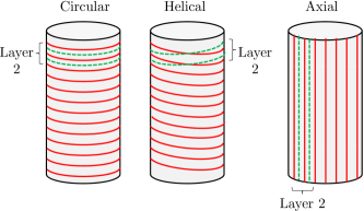
We constructed our Metglas magnetic shields by “winding” the foil onto the surface of cylindrical cardboard support forms. We tested several different winding techniques, which are illustrated schematically in Fig. 1.
-
•
“Circular” windings: Here, the foils were cut to a length equal to (actually, slightly greater than) the circumference of the shield, and then wound onto the surface of the form circumferentially. Thin (25.4-m thick) Kapton kapton tape was used to secure one end of these windings onto the form surface, and to secure the other (slightly overlapping) end to the short overlapped section of foil. The first layer of the shield consisted of of these such circular windings, with equal to the shield length divided by the foil width of 5.08 cm. Note that we were careful to minimize the gaps between adjacent circular windings.
The second layer of the shield was then wound in exactly the same manner, but an important point is that this layer consisted of circular windings, with the positions of the circular windings along the shield axis offset from those in the first layer by one-half of the foil width (i.e., by 2.54 cm) in order to “cover” the gaps between the adjacent circular windings in the first layer (see Fig. 1). The third/fifth/etc. and fourth/sixth/etc. layers were then constructed identically to the first and second layers, respectively.
-
•
“Helical” windings: Here, we used Kapton tape to adhere one end of the foil onto the form surface, and then proceeded to wind the foil as a single, continuous strip onto the surface of the shield from one end to the other in a spiraling, helical manner. Each successive turn overlapped the previous by approximately one-half of the material width, and an important point is that Kapton tape was used to secure each successive turn to the previous turn. Thus, a single-layer helical winding yielded an effective material thickness of times that of a single-layer circular winding (which, correspondingly, required times more material). Successive layers were wound with opposite helicities (e.g., first layer was wound as a right-handed helix, second layer as a left-handed helix, etc.).
-
•
“Axial” windings: Here, the foils were cut to a length equal to the length of the shield, and then aligned along the form surface in the axial direction. Again, Kapton tape was used to secure the two ends of the foil to the form surface. The first layer then consisted of of these such axial windings, with equal to the shield circumference divided by the foil width of 5.08 cm. Again, we were careful to minimize the gaps between adjacent axial windings.
The second layer of an axial winding was then constructed in exactly the same manner as the first layer. However, just as with the circular windings, the positions of the foils along the circumference were offset from those in the first layer by one-half of the foil width in order to “cover” the gaps between the adjacent foils (see Fig. 1). Note that the second layer also required foils. The third/fifth/etc. and fourth/sixth/etc. layers were then constructed identically to the first and second layers, respectively.
We believe a final important feature of our construction technique is that there were no (intentional) gaps between successive layers (e.g., between the first and second layers); the foils comprising any two successive layers were in direct contact. Also, if the shield included one or more axial foils, the outermost layer was then covered with a layer of plastic shrink wrap, which served to smooth the axial foils onto the curved shape of the cylindrical form surface. Finally, degaussing coils were wound onto the form in a toroidal geometry for circular and helical windings and in circular geometries (at multiple positions along the shield axis) for axial windings.
III Results
All of our measurements of the residual shielded fields within our magnetic shields were performed with an automated magnetic mapping system which consisted of a computer-controlled, three-axis stepper motor assembly. This system controlled the movement of a low-noise triple-axis fluxgate magnetometer (with a resolution better than Gauss), which was mounted on the end of a 2.1-m long non-magnetic arm (made of G10). Measurements of the residual shielded fields in the Earth’s magnetic field were conducted after a 60 Hz AC degaussing cycle. Our primary results are as follows.
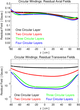
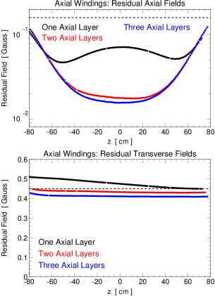
First, as briefly noted in Ref. 1, for cylindrical Metglas magnetic shields, axially-oriented (transversely-oriented) foils are not effective at shielding transverse (axial) external fields. However, explicit data were not shown. We present data demonstrating this effect in Figs. 2 and 3, which show results from measurements of the residual axial and transverse fields along the axis of magnetic shields consisting only of circular or axial windings. (Results from shields consisting only of helical windings are similar to those consisting only of circular windings.) These data show conclusively that circular windings are effective at shielding transverse external fields, but provide very little shielding against axial external fields, even with additional layering. Similarly, axial windings are effective at shielding axial external fields, but provide essentially no shielding against transverse external fields.
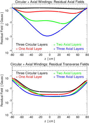
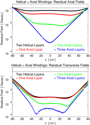
Second, Figs. 4 and 5 show results from measurements of the residual axial and transverse fields within shields which consisted of a circular plus axial winding combination, and a helical plus axial winding combination. We note again that these (open-ended) single-shell shields were 0.61 m in diameter, and 1.83 m in length, and consisted of only 5–6 layers of Metglas (i.e., thicknesses of 102–122 m). The results shown there were obtained with the axial windings wound directly onto (i.e., on top of, and in direct contact with) the underlying circular or helical windings. [Note that similar results were obtained with alternating layers of circular and axial windings.] As can be seen there, slightly better results were obtained for the helical plus axial winding combination, as compared to the circular plus axial winding combination (for similar material thicknesses).
For our helical plus axial winding combination, the residual axial and transverse fields in the center of our shield were Gauss and –400 Gauss, for external axial and transverse background fields of 0.16 Gauss and 0.45 Gauss, respectively. Thus, our measured axial and transverse shielding factors were and . Using standard formulae for the transverse sumner87 and axial edm_book shielding factors of a single-shell cylindrical shield with radius ( m), length ( m), thickness ( m), and relative permeability ,
| (1) |
our results suggest a relative permeability of in these external background fields, with consistent results obtained from the axial () and transverse () shielding factor measurements. Note that the values of these permeabilities are consistent, even though the above formula for the axial shielding factor assumes a cylindrical shield with end caps, whereas our shields were open-ended.
It is interesting to note that the axial shielding performance of our thin, single-shell shield in the Earth’s DC magnetic field is comparable to that achieved in Ref. 4 with a four-shell nested shield assembly in a low-frequency 0.1 G external field; this multiple-shell assembly included a single Permalloy shield and a three-shell Metglas shield assembly (composed of a total of 78 Metglas foil layers) with dimensions slightly larger than ours: 0.7-m diameters and 2.7-m lengths. Axial and transverse shielding factors of 180 and 5000 were achieved without magnetic shaking, with axial shielding factors of reported for single-shell Metglas shields (consisting of up to 30 Metglas foil layers).
Note that the measured residual fields near the ends of our cylinders were, in some cases, larger than the external background fields (see, e.g., Figs. 2 and 3). We attribute this to the magnetization of the shield in the external background field coupled to a theoretical residual field profile, especially for the residual axial (transverse) fields when the Metglas winding was circular (axial) [i.e., for the winding scenario demonstrated to yield only marginal shielding for a particlar orientation]. This effect was observed in finite-element-analysis calculations.
IV Summary
In summary, we have demonstrated a construction technique for large-scale, single-shell Metglas magnetic shields, consisting of little material (thicknesses of only 102–122 m), which yields a high DC axial shielding factor in the Earth’s magnetic field. We emphasize that we obtained these results in a passive DC environment, without the use of magnetic shaking or attenuation with any other magnetic coils. We believe that the results we obtained are the result of our careful construction technique, which minimizes the impact of any possible gaps between adjacent foil windings and layers.
Acknowledgements.
This work was supported in part by the U. S. Department of Energy Office of Nuclear Physics under Award Number DE-FG02-08ER41557, and by the University of Kentucky. We thank R. Golub and A. Pérez Galván for valuable discussions. B.P. thanks the Kellogg Radiation Laboratory at the California Institute of Technology for the hospitality during a visit during which time this article was written.References
- (1) I. Sasada, S. Kubo, and K. Harada, J. Appl. Phys. 64, 5696 (1988).
- (2) I. Sasada, T. Yamauchi, and Y. Yatomi, IEEE Trans. Magn. 32, 4923 (1996).
- (3) I. Sasada, T. Yamamoto, and T. Yamauchi, J. Appl. Phys. 79, 5490 (1996).
- (4) I. Sasada, E. Paperno, and H. Koide, J. Appl. Phys. 87, 5962 (2000).
- (5) K. Nagashima, I. Sasada, and K. Tashiro, IEEE Trans. Magn. 38, 3335 (2002).
- (6) http://www.metglas.com .
- (7) http://www.kaptontape.com .
- (8) T. J. Sumner, J. M. Pendlebury, and K. F. Smith, J. Phys. D 20, 1095 (1987).
- (9) I. B. Khriplovich and S. K. Lamoreaux, CP Violation Without Strangeness, Electric Dipole Moments of Particles, Atoms, and Molecules (Springer-Verlag, Berlin, 1997), pp. 36–40.