MAC Centered Cooperation - Synergistic Design of Network Coding, Multi-Packet Reception, and Improved Fairness to Increase Network Throughput††thanks: This work is sponsored by the Department of Defense under Air Force Contract FA8721-05-C-0002. Opinions, interpretations, recommendations, and conclusions are those of the authors and are not necessarily endorsed by the United States Government. Specifically, this work was supported by Information Systems of ASD(R&E). Contributions of the Irwin Mark Jacobs and Joan Klein Jacobs Presidential Fellowship have also been critical to the success of this project.
Abstract
We design a cross-layer approach to aid in developing a cooperative solution using multi-packet reception (MPR), network coding (NC), and medium access (MAC). We construct a model for the behavior of the IEEE 802.11 MAC protocol and apply it to key small canonical topology components and their larger counterparts. The results obtained from this model match the available experimental results with fidelity. Using this model, we show that fairness allocation by the IEEE 802.11 MAC can significantly impede performance; hence, we devise a new MAC that not only substantially improves throughput, but provides fairness to flows of information rather than to nodes. We show that cooperation between NC, MPR, and our new MAC achieves super-additive gains of up to 6.3 times that of routing with the standard IEEE 802.11 MAC. Furthermore, we extend the model to analyze our MAC’s asymptotic and throughput behaviors as the number of nodes increases or the MPR capability is limited to only a single node. Finally, we show that although network performance is reduced under substantial asymmetry or limited implementation of MPR to a central node, there are some important practical cases, even under these conditions, where MPR, NC, and their combination provide significant gains.
I Introduction
With the increase in wireless use, current wireless systems are throughput limited and are difficult to scale to large, dense networks. We develop a simple model that is easily extended to analyze the asymptotic regime and asymmetric traffic so that we can evaluate the performance of combining various techniques to increase network throughput and reduce overall delay.
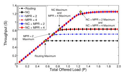
Network coding (NC), introduced by [1], and the proof that simple, linear network codes can achieve the multicast capacity by [2] led to a new heuristic inter-session NC scheme, Coding Opportunistically (COPE), for wireless networks. Proposed by Katti et. al. [3], COPE is a cooperative NC scheme that identifies coding opportunities and exploits them by forwarding multiple packets in a single transmission. While [2] showed that inter-session network coding is generally very difficult, COPE circumvents these complexity issues by decoding at each hop. The use of this simple coding scheme was shown to provide up to 3 to 4 times the throughput capacity over simply routing packets through the network. Implementing COPE in a 20-node IEEE 802.11 test bed, Katti et. al. provided empirical data, shown in the upper half of Fig. 1, that shows the benefits of using COPE in wireless mesh networks.
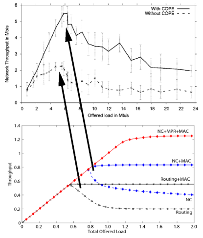
Sengupta et. al., [5] and Le et. al., [6] provided analyses of these experimental results, but only considered coding a maximum of two packets together at a time and did not address the interaction between NC and the medium access (MAC) fairness. As a result, their analyses provide throughput gains that are considerably smaller than the experimental results and do not explain the non-monotonic behavior of the results shown in Fig. 1. Zhao and Médard, [4], modeled the same experimental results, but showed that the fairness imposed by the IEEE 802.11 MAC explains this non-monotonic behavior. In addition, they demonstrated that the majority of the throughput gain achieved by using COPE is a result of coding three or more uncoded, or native, packets together at time. They showed that these gains are not reflected in three node network models, used in prior analyses, and at least five nodes are required to accurately capture the throughput gains from NC. The NC and routing curves in Fig. 1 show that the results obtained using their model for a simple 5-node cross component [4] is consistent with the empirical data from [3]. Furthermore, Seferoglu et. al. [7] used this 5-node component, and variants of them, to analyze TCP performance over coded wireless networks. Hence, we consider the 5-node cross component and additional 5-node components, as well as their extensions to any number of nodes, in order to understand the effects of combining NC and multi-packet reception (MPR) in larger networks.
While the performance of COPE significantly increases network throughput [3], it does not completely alleviate multi-user interference. With the development of new radio technologies, the ability to receive multiple packets simultaneously at the physical layer makes it possible to increase throughput and also has the potential to reduce contention among users [8]. The stability of slotted ALOHA with MPR, but not NC, was studied by [9], and several protocols implementing MPR have been proposed by [10] and [11]. However, little analysis has been performed in evaluating schemes that use both MPR and NC. Garcia-Luna-Aceves et al. [12] compared the use of NC to MPR, but did not consider their combined use. In addition, Rezaee et al. [13], provided an analysis of the combined use of NC and MPR in a fully connected network, but did not consider the effects of bottlenecks or multi-hop traffic.
We provide an analysis of the combined use of NC and MPR in a multi-hop, congested network. We extend the initial model proposed by [4] to include various topology configurations, asymmetric and asymptotic behavior, and various implementations of MPR in order to show that the achievable throughput when using NC in conjunction with MPR in a cooperative multi-hop network is super-additive. We then use this model to design a cross-layer solution that increases throughput subject to the constraint of fairness between flows, rather than between nodes, for congested network structures. While MAC fairness has been previously studied [14], our solution uses cooperation between nodes and takes into account the interaction among MPR, NC, and MAC. Using our simplified model, we then analyze the behavior of our solution as the traffic across the bottleneck becomes asymmetric, as well as in the asymptotic regime as the number of nodes in each component increases. Finally, we analyze the throughput behavior as we limit the MPR capability to a subset of nodes within the network.
The remainder of the paper is organized as follows: Section II describes the network models used in our analysis. Section III provides an analysis of NC and MPR for 5-node network components with the current IEEE 802.11 MAC fairness allocation. Section IV demonstrates the importance of considering the MAC when using a combined MPR and NC solution and provides an improved MAC that increases throughput while ensuring fairness to flows of information rather than to nodes. Sections V and VI investigate the effects of asymmetric network traffic and the gains obtained when considering delay in the asymptotic regime, respectively, with the new MAC. Section VII provides an analysis of the throughput when the MPR capability is limited to a subset of nodes. Finally, we conclude with a comparison of the results in Section VIII.
II Network Models and Parameters
This section develops a simple model that gives insight into cross-layer design of wireless networks by using NC, various MAC approaches, and MPR. We identify each network element’s fundamental behavior and model them using simple, intuitive methods so that various performance measures can be evaluated and design trade-offs can be weighed. Subsequent sub-sections identify specific behaviors of these elements and describe the abstractions and simplifications needed to make the model tractable.
The scenario considered consists of a wireless error-free packet network that is operated in fixed-length time-slots. Each node is half-duplex (i.e., cannot receive and transmit in the same time-slot), and only one packet can be sent per time-slot by any given node. If multiple packets are received by a node in the same time-slot without using MPR, it is assumed that a collision occurs and all packets are lost.
II-A Network Topologies
Our model uses the five node canonical components shown in Fig. 2. These components are of interest for two reasons. First, they form the primary structures in larger multi-hop networks that create bottlenecks and congestion. By looking at the traffic that travels through the center node, these components help us model the performance gains of multi-hop traffic under both low and high loads. Second, the COPE experimental results show that the majority of the coded packets generated in the network contained, on average, 3-4 native packets [3]. As a result, each component used must then be of sufficient size to capture the majority of the gains seen in [3]. The canonical topology components in Fig. 2 reflect all of the possible combinations of five node multi-hop networks that allow for the potential coding of up to four unencoded, or native, packets.
Each component has specific constraints due to its structure and will affect the performance of the MAC, NC, and MPR in different ways. In Fig. 2, we define these constraints through the use of a solid edge that depicts active, or primary communication, and a dotted edge that depicts passive, or overhear/listening communication. The absence of an edge between any two nodes indicates that all communication between the two nodes must be routed through the center node. The center node in each component is fully connected regardless of the topology, and traffic flows originating from the center require only a single hop to reach their destination. Within the “X” and partial “X” components, all flows originating from a node in a given set terminate at a node in the opposite set; and within the cross and partial cross component,s each traffic flow originating from a given node is terminated at the node directly opposite the center. For example, nodes , , and in the “X” component are fully connected and nodes , , and are also fully connected; but and are not connected to and . All traffic between any node and any node must travel through the center.


The study of topology components extended to an arbitrary number of transmitting nodes, where , aids in the analysis of performance and delay in larger networks. Sections IV and VI use the variants of the cross and “X” components shown in Fig. 3 to provide insight into the achievable gains and cross-layer design of networks employing the various technologies described here. For the cross component, there are transmitting edge nodes and a single center, or relay, node. All edge nodes are connected with the center node and connected with all other edge nodes except the one directly opposite the center. Each node generates traffic destined only for the node directly opposite the center. For the “X” component, there are also transmitting edge nodes and a single center node. The edge nodes are split into two sets, and . All edge nodes within a given set are fully connected and are also connected to the center. Each node generates traffic destined for a node within a different set. Furthermore, it is assumed that the set of transmitting nodes is stable and does not frequently change. This eliminates the need to consider a decision mechanism for determining which nodes are transmitting.
II-B Network Coding Model
Network coding is modeled by considering the ability of a given node to combine multiple packets together. We use COPE [3] as a case study. COPE inserts a coding shim between the IP and MAC layers and uses the broadcast nature of the wireless channel to opportunistically code packets from different nodes using a simple XOR operation. The wireless channel enables each node to overhear packets that can be used to help decode any subsequently received encoded packets.
In the proposed model, each encoded packet is sent if and only if it can be decoded by the intended recipients (i.e., the intended recipients have overheard enough native packets, or degrees of freedom, to enable each encoded packet to be decoded). In addition, only the center node will encode packets together while each edge node will always transmit their packets unencoded due to the limitations imposed by the components in Figures 2 and 3. The model further assumes that feedback is perfect and that each node knows the native packets overheard by its neighbors. Consistent with COPE’s implementation, each packet is sent as a broadcast transmission on the channel at the first opportunity without delay and each information flow does not exercise congestion control (i.e., each packet generated is part of a UDP session). Finally, neither the complexity of the coding or decoding operations nor any other aspects of the NC implementation found in [3] are considered since their contributions to the overall network performance is small.
II-C IEEE 802.11 MAC Model
We model the IEEE 802.11 MAC’s distributed coordination function (DCF) [15], which uses carrier sense multiple access with collision avoidance (CSMA/CA) as the method in which a node accesses the channel. In order to develop the model, we first identify the behavior of the DCF over a sufficiently long period of time. The non-monotonic behavior observed in the COPE experiments shown in Fig. 1 was noted by [4] to be a result of the IEEE 802.11 MAC fairness mechanism, which essentially distributes channel resources equally among competing nodes. This realization is also consistent with the analysis and simulation results presented in [16], which showed that the probability of a node successfully accessing the channel converges to for competing nodes. The MAC model used for each non-MPR case below captures this limitation with fidelity by limiting each node’s access to the channel to of the time when the channel is fully saturated, while the random access protocols are simplified so they match the experimental throughput behaviors found in [3]. For example, the non-monotonic behavior in Figure 1 is a result of both collisions and fairness; but the total effects of collisions on throughput from either hidden nodes or identical back-off times are small in relation to the effects of the IEEE 802.11 MAC fairness mechanisms. When using MPR, extensions to the MAC model are required where Section II-D explains these extensions and the reasons for their necessity.
The MAC model also assumes that the request-to-send/clear-to-send (RTS/CTS) feature of the DCF is not used, which is consistent with the IEEE 802.11 ad-hoc mode and the COPE experiments [3]. Furthermore, the model does not consider the additional effects on overall throughput associated with various implementation aspects of the DCF. Since the DCF introduces a constant overhead that lowers the throughput to about 20% to 30% of the bit rate depending on the variant of 802.11 used [16], these assumptions provide upper bounds to the achievable throughput. In addition, implementing MPR and NC reduces the number of times each node is required to access the channel and therefore reduces the overhead incurred by the DCF. This results in tighter throughput bounds than when MPR and NC are not used and also provides an estimate for the MPR and NC throughput gains that can be achieved. Finally, any additional time needed to acknowledge transmitted packets is included in the duration of each of the model’s time-slots. This allows for a new packet to be transmitted in each integer time-slot.
II-D Multi-Packet Reception Model
In general, MPR allows for the correct reception at the physical layer of one or more packets involved in a collision. Several techniques can be used to implement MPR in a wireless network, for example: Code Division Multiple Access (CDMA), Space Division Multiple Access (SDMA), Orthogonal Frequency Division Multiple Access (OFMDA), etc. The fundamental concept behind each of these technologies is that a receiver is able to separate signals transmitted simultaneously from different nodes and then extract the required data from each transmission.
The analysis and simulations in the remainder of the paper will evaluate the potential throughput gains using two MPR models. In both, the number of simultaneous transmissions that a node can successfully receive without a collision is where only are considered in this paper. In the first model, CSMA/CA is strictly enforced for . If a node senses any other node transmitting, it will follow the 802.11 DCF algorithm and not attempt to transmit until the channel is idle again. This model essentially uses MPR to minimize the hidden terminal problem. When , a slight generalization of the traditional CSMA/CA is required. We pick the combination of transmitting nodes such that the average number of transmissions received by any given node within the network is maximized. It is important to note that this generalization allows strictly fewer than four adjacent nodes to transmit at the same time. For example, consider the generalized “X” component shown in Fig. 3. We will only allow two nodes in set and only two nodes in set to transmit at the same time, which maximizes the number of packets that each edge node overhears. In the second model (referred to as MPR-adapted CSMA in the remainder of the paper), a node will be allowed to transmit as long as the number of simultaneous transmissions sensed is less than . For the generalized “X” component, this model will allow for up to four nodes within a single set to transmit at the same time. In either model, up to packets can be sent simultaneously in the same time-slot.
When considering the IEEE 802.11 MAC model developed in the previous sub-section, the fraction of time each node accesses the channel under saturated conditions is dependent on the MPR model and component used. In general, the time each node will be able to access the channel as it saturates becomes approximately where the MPR model and component used will dictate the exact allocation of channel resources among the set of nodes. Specific details and additional explanation will be expanded upon in later sections.
II-E Additional Model Assumptions and Parameters
The channel is divided into 100 time-slots where each time-slot uses of the total amount of channel resources available to the transmitting nodes. Successful transmission of each packet requires a full time-slot therefore requiring of the total amount of channel resources. Performance is evaluated at various values of where is defined as the total number of packets in the network and is deterministic. In order to model stochastic packet arrivals, these packets are distributed to each node where each node has , , packets and is distributed according to a joint binomial distribution, given and , with parameters and . The number of packets each node has to send will be referenced in later sections as the fraction of the total channel resources, or load , required to send all packets one hop (i.e., ). In addition, the total offered load to the network is deterministic, given , and is defined as .
In order to determine specific network behaviors over the range of , we define the total network component load as the load induced in the network component as a result of NC, MPR, and MAC. This allows us to specify three regimes which are of particular interest. These regimes are: the unsaturated throughput regime (), the maximum throughput regime (), and the saturated throughput regime (). In general, the component load when routing packets without NC and/or MPR and otherwise. Specifically, the component load is a random variable, with sample value , that is defined as the sum of the load induced by relaying packets through the center node , and the load required to send each native packet one-hop (i.e., . The sample values, and , for and respectively are bounded by:
| (1) |
| (2) |
where the coefficient is the number of packets that can be encoded together by , and is the fraction of time, or load, needed to send all of the packets originating at one-hop. The relay load is a function of the number of packets that can be encoded together by and only counts the load required to send relayed packets a second hop. The one-hop load consists of the load needed to send all of the edge node’s packets to , which is a function of , and the load required by to send its own packets to the edge nodes. The lower bounds for each are functions of the component’s configuration as well as the difference in each node’s initial load. Each lower bound is met with equality if each , , and . The upper bound in eq. (1) is met with equality if no coding opportunities occur at and in eq. (2) if no simultaneous transmissions occur. Given sample values of each node’s load , , and the component, both and are deterministic. Section III will provide additional clarification and examples.
Furthermore, the allocated load is defined as the amount of channel resources given to each node in the network as a result of the MAC. When , each node is allocated enough time-slots to send all of its packets through the component. The allocated load in this case is for and the load allocated to the center node is the sum of the load originating from the center and the load resulting from relaying packets (i.e., ). As the MAC saturates (i.e., ) the allocated load for each node is , , and .
Finally, the throughput is defined in relation to the number of packets that reach their respective sinks within the component. For , the channel is not saturated so the MAC does not limit each node from sending all of its packets. As a result, the throughput . For , the channel is saturated and the MAC must limit the number of transmissions made by each node in order to remain within the channel constraints (i.e., the amount of resources allocated to the sum of nodes can be no more than one or ). The MAC limits the number of transmissions by adjusting the allocated load for each node according to the proposed model. In the saturated regime, the throughput saturates to the amount of information that the center node can transmit per time-slot. For example, the IEEE 802.11 MAC will distribute channel resources equally among each transmitting node and the center node will only receive of the available resources. The total amount of information that the center node transmits is then equal to the throughput. Section III will provide greater detail into calculating the throughput with and without NC and MPR.
III Multi-Packet Reception and Network Coding Performance Analysis
With each of the network components shown in Fig. 2, we analyze the component performance with and without the use of NC and MPR. We also consider both unicast and broadcast traffic.
III-A “X” Topology Component Analysis
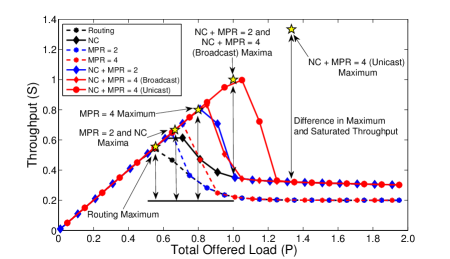
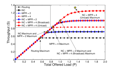
The “X” component, depicted in Fig. 2(a), will be used to provide insight into the analysis and to help explain the simulation results. Fig. 4 shows both the analytical and simulated throughput for each case discussed below. The stars in the figure indicate the maximum achievable throughput obtained from analysis when the MPR and/or NC gain is maximized. The curves show the simulated throughput, which is averaged over the distribution discussed in Section II.
III-A1 Routing (No Network Coding, )
We will use routing as the baseline for our analysis. Consistent with the results found in [3] and the analysis performed in [4], the throughput increases linearly within the non-saturated region, , and it reaches its maximum of , depicted by a star in Fig. 4, when . For symmetric loads at each node (i.e., , ), each source’s individual load is for .
The throughput saturates for . Initially, the IEEE 802.11 MAC allocates time slots to nodes requiring more resources. The throughput is therefore the amount of time is able to transmit, , which decreases as increases. The network component completely saturates when each node requires a large fraction of the available time-slots and the MAC restricts each node’s access to the channel by ensuring fairness among all nodes (i.e., for ). The total saturated throughput is equal to the total amount of information that transmits (i.e., ).
III-A2 Network Coding Only ()
When using NC, there are limitations imposed by the component’s configuration. Packets from different nodes within the same set (i.e., and ) cannot be coded together because they are forwarded through . The center node must make a minimum of two transmissions for every four packets it receives from different edge nodes in order to ensure that each destination node obtains enough degrees of freedom to decode. In Fig. 4, when , NC is seen to provide no additional gains over the use of routing alone since can forward each packet received without the MAC limiting its channel use. For NC is instrumental in achieving the throughput shown.
The MAC does not limit channel resources until the maximum throughput of is reached. Assuming symmetric source loads, this maximum occurs when for and . At this maximum, the MAC ensures fairness among all competing nodes and the throughput saturates for . The non-monotonic behavior is again due to the fairness aspect of the IEEE 802.11 MAC, and it is evident that the IEEE 802.11 MAC protocol restricts the total throughput when the network is saturated.
III-A3 Multi-Packet Reception of Order 2 and 4 (No Network Coding and )
MPR is similar to the routing case described earlier except we now allow a maximum of edge nodes to transmit within a given time-slot. For , the total time used by all of the edge nodes to transmit their packets to is that needed by routing while the center node cannot transmit multiple packets simultaneously and must transmit each received packet individually. Using CSMA, which restricts nodes opposite each other to transmit at the same time, the point at which the protocol saturates for symmetric source loads occurs when for and . This maximum, which yields a throughput of , occurs when each source has equal loads and is reflected in Fig. 4 as a star. The throughput saturates to the same throughput as routing for values of and the gain for is one due to the suboptimal saturation behavior of the protocol.
The behavior for is the same as that for except the maximum of occurs when and . We allow all of the edge nodes to transmit their packets to simultaneously using MPR-adapted CSMA described in Section II. This requires a total of of the time slots. Node then sends each node’s packet individually, including its own, to the intended recipient requiring the remainder of the time-slots to finish each unicast/broadcast transmission. As increases, the MAC limits each node’s number of available time-slots and saturates to . Again, the gain in the saturated region for is equal to the cases of and routing.
The gain as a result of the use of MPR depends on an adequate number of source nodes with information to send. If is greater than the total number of nodes with information to send (i.e., ) the MPR gain will be less than when . In addition, the achievable gain for implementations using stochastic message arrival and transmission times will be upper-bounded by the results shown in this section and lower-bounded by the throughput for the non-MPR (routing) case seen in Fig. 4.
III-A4 Network Coding with Multi-Packet Reception of Order 2 and 4 (
The case when MPR is combined with NC results in further improvement as seen in Fig. 4. Unlike the case where we considered MPR alone, the order in which each node transmits and symmetric traffic across the component are crucial to achieving the maximum throughput. As a result, we continue to use CSMA to ensure nodes in opposite sets transmit at the same time so that we both facilitate opportunistic listening and enable coding opportunities by .
For , the throughput increases linearly until it reaches its maximum at when for and . It then saturates to the NC throughput for . The decrease in throughput within the saturated region is a direct result of the IEEE 802.11 MAC which enforces fairness among nodes and is not a result of the averaging over the stochastic load distributions. The averaged simulation results and maximum throughput shown in Fig. 4 for is achieved for both unicast and broadcast traffic when using CSMA to force nodes from different sets to transmit to at the same time. Suppose we use the MPR-adapted CSMA model so that any two nodes can transmit simultaneously. The throughput will be the same for unicast traffic, but the broadcast throughput will be upper bounded by the unicast throughput and lower bounded by the without NC case. Furthermore, this shows that the broadcast throughput is dependent on the mechanism of determining the order of transmissions, such as CSMA, round-robin, or other similar scheme, within the wireless channel.
For , the maximum unicast throughput of is achieved when allowing all four source nodes to transmit to the center at the same time (i.e., MPR-adapted CSMA is used). The center node codes a maximum of two native packets together from different source node sets and transmits two coded packets back to the edge nodes, including its own uncoded packets, in order to complete all of the unicast sessions. At the completion of all unicast sessions, each node still requires a maximum of one additional degree of freedom to complete the broadcast session. Allowing to code all of the native edge node packets together and send one additional coded transmission enables each node to extract the required degree of freedom and obtain the full set of transmitted messages. The maximum throughput for this case is therefore the same as the case for NC with and is equal to . It is important to note that the simulated average throughput shown in Fig. 4 for both cases discussed in this sub-section do not reach the maxima found through analysis, indicated by stars in the figure. This is due to the stochastic load distribution, which results in asymmetric traffic among the set of nodes. Should each node have an equal amount of information to send, the maxima found above will be reached.
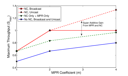
Fig. 5 shows a summary of our analysis by plotting the maximum unicast and broadcast throughput as a function of the MPR capability. In addition, it illustrates the super-additive behavior of the throughput when MPR is used in conjunction with NC by comparing this throughput with the throughput that would be obtained by adding the individual gains obtained using MPR and NC separately.
III-B Cross and Partial Topology Component Analysis
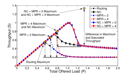
Increasing cooperation between nodes by increasing the number neighbors each node has results in higher throughput, but there are limitations to the benefits from increasing the number of overhear/listen edges. We first consider the cross component shown in Fig. 2(b), and conduct a similar analysis performed for the “X” component. All cases not involving NC are unaffected by the connectivity of the component, but the maximum throughput for those cases with NC is increased in the saturated regime. Intuitively, the reason for the increase in saturated throughput is due to the ability of the center node to effectively code at most four native packets together. The analysis is identical to the discussion in Section III-A and the results are presented in Fig. 6. The figure show both the analytical results, indicated by the stars, and the simulation results, indicated by the curves.
Considering the other possible 5-node components, shown in Fig. 2(c) and (d), we find that the addition or removal of an overhear/listen edge has little impact on the maximum throughput. In the case of the partial cross component, Fig. 2(d), the removal of a single edge results in the maximum throughput found using the unmodified “X” component. In the case of the partial “X” component, Fig. 2(c), the gain resulting from the use of NC is reduced; and as a result, the throughput decreases. It can be verified using the methods described above that the maximum throughput for the case where NC and is for unicast traffic and for broadcast traffic. This is only a slight reduction in throughput from the unmodified “X” component’s throughput. On the other hand when , the maximum is the same as that found for the partial cross and “X” components. Both the partial cross and partial “X” components highlight that the use of MPR can potentially inhibit the effectiveness of NC. Because each node is half-duplex, increasing restricts each node’s ability to overhear other node’s transmissions.
IV Improving the MAC Fairness Protocol
The IEEE 802.11 MAC was initially designed for use in infrastructure wireless networks, yet it is consistently used as the primary medium access method in ad-hoc, multi-hop networks. Section III showed that the IEEE 802.11 MAC’s use in these ad-hoc, multi-hop networks results in the non-monotonic saturation behavior observed in the COPE experiments [3]. In this section, we propose an improved MAC approach developed for use in ad-hoc, multi-hop networks that eliminates this non-monotonic behavior. Furthermore, our MAC provides fairness to flows rather than to nodes. Our improved protocol approach allocates resources proportional to the number of different flows passing through a given node when the network saturates. While allocating more resources to flows originating at the center and less resources to flows originated at edge nodes would yield even higher throughput, our policy ensures that each flow of information is given the same priority.
The allocated number of time-slots each node receives so that the throughput is maximized, subject to the flow constraints and , is divided into the cases below where is the fraction of time slots allocated to each edge node and is the fraction of time slots allocated to the center node. Similar to Section III, the throughput when NC is not used and . When NC is used, the throughput is a function of the number of packets that can be effectively coded together, which is dependent on the MPR coefficient , the use of CSMA, and the traffic type (unicast or broadcast). The cases addressed include:
-
•
Cross Topology Component with Unicast Traffic or Broadcast Traffic: Assuming that there are no constraints on the order in which each node transmits to the center node, the allocation of resources is the same for both unicast and broadcast sessions. Without NC, the center node will require a number of time slots equal to the number of transmitting source nodes . With NC, throughput is maximized by ensuring the center node codes the maximum number of native packets together. Generalizing for and , as well as considering only integer numbers of time-slots:
(3) and
(4) When MPR-adapted CSMA is used, we define for . When CSMA is used, we define for . In addition, the term for all situations where . Furthermore, eq. (4) is met with equality if CSMA is used for and 2 as well as for all cases when . Eq. (4) may be met with inequality when MPR-adapted CSMA is used for since there is a non-zero probability that any given node may miss a packet from a node in which it can overhear while it is transmitting. Using a scheme such as CSMA results in a significant throughput gain for small but becomes insignificant as grows.
-
•
“X” Topology Component: The fraction of time slots allocated to each node for unicast traffic and either the CSMA or MPR-adapted CSMA models is:
(5) and
(6) When considering broadcast traffic, additional degrees of freedom must be sent by the center to complete the session. Without NC, equations 5 and 6 hold. With NC, there is a possibility that each destination node will require a maximum of one additional degree of freedom per node for or three degrees of freedom per node for when either or and the order of node transmission is not enforced (i.e., MPR-adapted CSMA). In order to provide these degrees of freedom, the center node must send send additional coded packets. The fraction of time-slots each node receives for broadcast traffic, , with NC is then bounded by:
(7) and
(8) where is maximized when and traffic across the center is symmetric. It is minimized when and differ most and traffic across the center is asymmetric.
We applied our revised fairness protocol to both the 5-node cross and “X” components using the same model described in Section II. The throughput, shown in Fig. 7 and 8, saturates at the maxima found in Section III for each component. As the network saturates, the improved fairness protocol limits each node’s access to the channel. When each node’s load is greater than the limit imposed by the protocol, the total throughput will saturate at the maxima. As the simulation results represented by the curves in both figures indicate, the maxima may not be reached due to asymmetry in each node’s load and is the reason why the average throughput shown in Fig. 7 and 8 do not initially saturate at their maxima. As the network initially saturates, some nodes will have higher loads than others resulting in a lower throughput than when each node has the same load which occurs as increases towards infinity.
V Performance of MPR and Network Coding with Asymmetric Traffic
The performance of NC and MPR in networks with bottlenecks is highly dependent on the symmetry of traffic across the bottleneck. Situations in which the traffic is approximately symmetric, or equal, across the bottleneck maximizes the performance gains provided by both NC and MPR as shown by the stars in Fig. 4, 6, 7, and 8. The curves in each figure show that the maxima are not initially reached since each curve represents an average over the instantaneous asymmetries in traffic. For the purposes of analyzing the effects of asymmetric traffic, the “X” component is used as the primary component in our analysis since its limitations from the reduced number of nodes any given edge node can overhear compounds the effects of asymmetric traffic on network throughput. In addition, we define the asymmetry ratio as:
| (9) |
where and are the number of packets that each node and , respectively, needs to send to a given node on the opposite side of the relay.
Two different asymmetry scenarios are addressed. The first addresses the effects of asymmetry with a MAC that limits the transmissions of nodes from the same set (i.e., nodes within the same set do not transmit at the same time unless the degree of MPR requires that they do so). In this scenario, both the effectiveness of NC and MPR is diminished as increases. When , only a single node from a set will transmit in a time-slot, corresponding to CSMA. As traffic becomes more asymmetric, one set of nodes will eventually run out of data and the other set will be forced to continue sending data to the relay one node at a time. For , two nodes from the same set will transmit in the same time-slot since the component contains only two sets of nodes, which corresponds to MPR-adapted CSMA. When NC is used, the limitations induced by the component force the center node to transmit packets unencoded when is large. For example, as increases, the center node will run out of data from different sets to code together. As a result, each packet that needs to be relayed must be forwarded individually to ensure that the necessary degrees of freedom are exchanged.
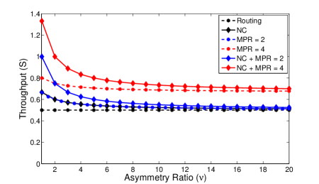
Fig. 9 shows how asymmetric traffic from different sets affects network throughput. For the case when with or without NC, the throughput is maximized when traffic is perfectly symmetric but saturates to the throughput obtained for the routing case. Intuitively, this can be seen by limiting all traffic so that it originates from a single set of nodes. The MAC will restrict transmission from each node to the center, which eliminates the gain resulting from the use of MPR; and the center node must send each relayed packet uncoded to the next hop, which eliminates the gain resulting from NC. The case for is similar to that of the case except that only a maximum of two nodes in a set are allowed to transmit in the same time slot. The throughput will saturate for large to the maximum throughput of .
The second scenario involves the use of a MAC that does not limit the number of nodes that simultaneously transmit in either set or . The MAC allows nodes within the same set to take advantage of MPR and does not restrict multiple nodes from sending to the relay in a given time slot. If only nodes within the same set have data to send, the MAC allows for up to nodes to send their respective packets to the relay. In this scenario, the effectiveness of MPR is not diminished since MPR can be fully utilized regardless of where the traffic is originates. This results in a constant throughput, independent of , of for the case and for the case. On the other hand, the effectiveness of NC still decreases as increases. Similar to the first scenario, the throughput for each case involving NC will saturate to the routing or MPR only throughput for each case involving NC as increases.
This section emphasizes that implementing a MAC that allows for the full employment of MPR provides significant throughput gains over a more restrictive MAC, such as one that uses a CSMA scheme. Finally, it is important to note, that in the presence of erasures the potential gains are significant even with asymmetric traffic. While NC may not necessarily increase throughput under highly asymmetric data, the NC gain will manifest itself when recovering from packet erasures.
VI Performance of Network Coding and MPR with Large N
The gain provided by the use of MPR and NC is dependent on the number of transmitting nodes within the component. While the gain manifests itself in the throughput of each canonical component, the major benefit is realized in the delay, or time it takes to complete all flows. For purposes of illustration, we restrict our analysis to the cases in which we have a restrictive MAC which uses CSMA, symmetric traffic across each component, and the improved fairness protocol. Using eq. (3) - (6), relaxing the integer constraints, and assuming an equal number of nodes in each set within the “X” component, we take the limit of the throughput for each canonical component:
| (10) |
| (11) |
It is clear from the above results that the gain has a dependency on the connectivity of the network. As the network becomes more connected, the interaction between NC and MPR combine to create gains that are super-additive.
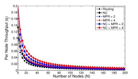
Considering the per-node throughput for , we see from eq. (5) that the throughput for both the original IEEE 802.11 MAC and improved MAC scales on the order of . Fig. 10 shows the per-node throughput behavior for the “X” component, using the improved MAC, as a function of the number of nodes. As expected, the per-node throughput asymptotically approaches zero as grows. While there are gains from MPR and NC for moderately sized networks (i.e., ) the throughput gains are limited for larger ones.
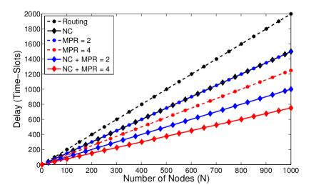
On the other hand, there are significant gains from MPR and NC, while using the improved MAC, when considering the delay, or total time to complete all sessions. We evaluate the delay by distributing a single packet to each node and determine the time it takes for all packets to reach their intended destinations. Fig. 11 shows the total time to complete all flows within an “X” component as grows. It can be verified from Fig. 11 that the delay gains for the MPR with or and NC cases are approximately and respectively for large .
VII MPR Limited to Central Node
Since implementing MPR in a system may be a difficult and costly upgrade, we now look at the throughput gains if we target strategic nodes for implementing MPR and leave the rest without the capability. The limitation of not having MPR at each edge node, as would be expected, reduces the effectiveness of opportunistic NC and limits the total number of packets that the center node can code together.
We continue to use CSMA as explained in Section II. We deterministically distribute an equal number of packets to each node and calculate the throughput using as the number of transmitting nodes increases towards infinity. We further assume that each node has the ability to capture a packet. That is, if multiple transmissions occur in a given time-slot, a node without MPR will receive one transmission without error and treat the remaining transmissions as noise. If capture is not feasible, the NC with MPR gain will equal the NC alone gain for components such as the cross. The NC with MPR gain for less connected topologies, in contrast, will be higher depending on the implementation of the MAC since the topology limitations decrease the probability of two nodes’ transmissions conflicting. For ease of further explanation, we will assume in the remainder of the paper that every node has the ability to capture packets.
The number of additional packets that the center node must send when each edge node does not have MPR is dependent on . Limiting MPR to the center node essentially splits a component into disjoint sets where all edge nodes in a set are fully connected and each node is connected to the center. An MPR of will result in two disjoint sets that requires the center node to send degrees of freedom to each edge node in order to complete all unicast and broadcast sessions. The first term in this equation is the number of transmissions needed to relay all traffic from each of the edge nodes and the second is the number of transmissions needed to send the center’s own traffic. In the case of the “X” component, the division has already been performed as a result of the topology configuration so the throughput is the same as that found in Section IV. The throughput for the cross component becomes the same as that of the “X” component as a result of the limited implementation of MPR. An MPR of results in four disjoint sets that requires the center node to send degrees of freedom to the set of edge nodes to complete all unicast sessions and degrees of freedom to each edge node to complete the broadcast session. Within both components, the result of increasing is offset by the requirement of the center node to send additional degrees of freedom. The broadcast throughput for both components becomes upper bounded by the throughput of the “X” component when using both NC and ; and the unicast throughput for NC with is upper bounded by for both components.
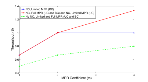
The cases where NC is not used are unaffected by limiting MPR to the center node only. Since the center must forward all packets individually, it inherently communicates all of the necessary degrees of freedom to each of the edge nodes. These results are displayed in Fig. 12 for the “X” component as we let increase towards infinity and consider fully saturated, symmetric loading. This figure was generated using a similar analysis as performed in Section VI. When considering the cross component, the throughput with limited MPR is the same as that shown in the above figure, but the NC + MPR throughput with MPR implemented at each node is , , and for , , and respectively. This shows that there are significant throughput gains when considering NC with MPR for topologies similar to the “X” component, but little for topologies that are more connected or for larger values of .
VIII Conclusion
We have provided a lower bound to the gains in total throughput from MPR and NC for components that create traffic bottlenecks in large networks. We provided an analysis of the total throughput and showed that the effectiveness of NC is highly dependent on the use of MPR, and that the combined use of MPR and NC results in super-additive gains. In addition, we evaluated the fairness imposed by the IEEE 802.11 MAC and showed that the NC + MPR gain at saturation is not maximized. We argued that while the current IEEE 802.11 MAC is fair to nodes, it is inherently unfair to flows of information in multi-hop networks. We further generalized each scenario for both unicast and broadcast traffic.
We then used our simple, validated model to design a new MAC approach, in conjunction with MPR and NC, that cooperatively allocates channel resources by providing a greater proportion of resources to bottle-necked nodes and less to source nodes. The new MAC ensures fairness among information flows rather than nodes through the cooperative allocation of bandwidth between the set of edge nodes and the center node. Furthermore, the new MAC ensures that each node is able to access the channel in contrast to the IEEE 802.11 MAC which has a tendency to starve some nodes under high loads. Our proposed approach, specifically designed for networks using NC and MPR, shows a significant increase in the achievable throughput of as much as 6.3 times the throughput when neither NC nor MPR is used in similar networks. While only four specific 5-node canonical topology components and their extensions to nodes were addressed, these components serve as a basis for further investigation on how channel resource allocation should be performed in larger, more complex networks.
In addition, we analyzed the scalability of the canonical topology components. We showed that the gains provided by the use of MPR and NC are highly dependent on the connectivity of the network. While the asymptotic per-node throughput is not large, the asymptotic gains in the delay are substantial. We further showed that asymmetric loads across a bottleneck can impact network performance when using both NC and MPR, although NC and MPR still provide significant gains for low to medium asymmetric loads. Finally, we showed that limiting the distribution of the MPR capability to only a subset of nodes within a network can result in a drastic reduction in performance for some canonical topologies. Less connected components such as the “X”, which are much more likely to be physically realizable in contrast to the cross component, are less affected by limiting the implementation of MPR to only a subset of nodes. In contrast, components that are more connected, such as the cross, lose much of the throughput gain resulting from combining NC with MPR. All of the analyses outlined in this paper show that the cooperative use of MPR, NC, and MAC in a given network is critical to achieving the maximum gain.
References
- [1] R. Ahlswede, N. Cai, S.-Y. Li, and R. Yeung, “Network Information Flow,” IEEE Trans. Inf. Theory, vol. 46, pp. 1204 - 1216, 2000.
- [2] R. Koetter and M. Médard, “An Algebraic Approach to Network Coding,” IEEE/ACM Trans. Netw., vol. 11, pp. 782 - 795, 2003.
- [3] S. Katti, H. Rahul, W. Hu, D. Katabi, M. Médard, and J. Crowcroft, “XORs in the Air: Practical Wireless Network Coding,” IEEE/ACM Trans. Netw., vol. 16, pp. 497 - 510, 2008.
- [4] F. Zhao and M. Médard, “On Analyzing and Improving COPE Performance,” in ITA, 2010.
- [5] S. Sengupta, S. Rayanchu, and S. Banerjee, “An Analysis of Wireless Network Coding for Unicast Sessions: The Case for Coding-Aware Routing,” in INFOCOM, 2007.
- [6] J. Le, J. Lui, and D. M. Chiu, “How Many Packets Can We Encode? - An Analysis of Practical Wireless Network Coding,” in INFOCOM, 2008.
- [7] H. Seferoglu and A. Markopoulou, “Network Coding-Aware Queue Management for Unicast Flows over Coded Wireless Networks,” in NetCod, 2010.
- [8] J. J. Garcia-Luna-Aceves, H. R. Sadjadpour, and Z. Wang, “Challenges: Towards Truly Scalable Ad Hoc Networks,” in MobiCom, 2007.
- [9] S. Ghez, S. Verdú, and S. Schwartz, “Stability Properties of Slotted Aloha with Multipacket Reception Capability,” IEEE Trans. Autom. Control, vol. 33, pp. 640 - 649, 1988.
- [10] Q. Zhao and L. Tong, “A Multiqueue Service Room MAC Protocol for Wireless Networks with Multipacket Reception,” IEEE/ACM Trans. Netw., vol. 11, pp. 125 - 137, 2003.
- [11] G. Celik, G. Zussman, W. Khan, and E. Modiano, “MAC for Networks with Multipacket Reception Capability and Spatially Distributed Nodes,” IEEE Trans. Mobile Comput., vol. 9, pp. 226 - 240, 2010.
- [12] J. J. Garcia-Luna-Aceves, H. R. Sadjadpour, and Z. Wang, “Extending the Capacity of Ad Hoc Networks Beyond Network Coding,” in IWCMC, 2007.
- [13] A. Rezaee, L. Zeger, and M. Médard, “Multi-Packet Reception and Network Coding,” in MILCOM, 2010.
- [14] H. Abuzanat, B. Trouillet, and A. Toguyeni, “Routing Fairness Model for QoS Optimization in Wireless Network,” in SENSORCOMM, 2008.
- [15] IEEE Std 802.11-2007, Dec. 2007, Std.
- [16] A. Duda, “Understanding the Performance of 802.11 Networks,” in PIMRC, 2008.