Measuring the Virgo area tilt noise with a laser gyroscope
We report on the measurements of tilt noise performed at the Virgo site with a ring laser gyroscope. The apparatus is a He-Ne laser operating in a square cavity mounted on a vertical plane perpendicular to the north-south arm of the inteferometer. We discuss the possibility of using the ring laser signal to improve the performances of the control system of the Virgo seismic suspensions. The comparison between the ring laser signal and the control signals for the longitudinal traslations of the inverted pendulum (IP) shows remarkable coherence in the frequency range .
1 Introduction
Over the last 40 years ring laser gyroscopes became one of the most important instruments in the field of inertial navigation and precise rotation measurements. They have high resolution, excellent stability and a wide dynamic range. Furthermore no spinning mechanical parts are required, so these sensors can be manufactured in a very robust way and with a very high rejection of linear cinematic and gravitational accelerations from the rotational signal. More recently, over the last 10 years, mainly thanks to the strong improvement in the mirror manufacture technology, very large perimeter ring laser gyroscopes have found application in Geodesy and General Relativity tests seem feasible in the near future .
In the last years “G” , a monolithic structure of zerodur (a glass-ceramic with ultra-low thermal expansion coefficient) supporting a squared cavity 4 m in side, operating by the Geodetic Observatory of Wettzel (Germany), was able to detect very small rotation signals like the twice-daily variations of the earth rotation axis due to solid earth tides , and the nearly diurnal retrograde polar motion of the instantaneous rotation pole caused by the lunisolar torques . Comparable results have also been obtained by the New Zealand ring-laser research group. Inside the underground laboratory located in Cashmere, Christchurch, New Zealand, operated, the world largest gyrolaser: the UG2, a rectangle 21 m x 40 m .
In this paper we present the experimental results concerning the use of a meter size gyrolaser as a very sensitive tilt sensor. The system has been installed inside the Virgo central area with the aim of performing seismic monitoring and improving the control of the inertial suspensions of the Virgo interferometer. The control system for the IP works only in four degrees of freedom; three translational and yaw. Due to the equivalence principle, the linear accelerometers providing the feedback signals are fundamentally unable to distinguish between linear accelerations and tilts. The generic response of an accelerometer, sensitive to the linear acceleration along the longitudinal direction , is given by: where is the modulus of the local gravity vector, and is the angle between the direction and the horizontal plane.
The consequences of the coupling between accelerations and tilts are particularly dramatic for the active control of the IP . In closed loop conditions a rotation introduces a positive feedback in the the system and thus extra noise. A direct measurement of the tilt is expected to provide the correction to the measurement of acceleration and then reduce the overall RMS displacements of the IP. This would in turn improve the sensitivity performances for the gravitational antenna. The Advanced Virgo project foreseen the development of tilt sensors having a sensitivity at the level of in the range in order to decouple the pure rotational motion from the linear acceleration measurements (see: Virgo note VIR-027A-09 (26 May 2009)).
In the following we will briefly explain the working principles of laser gyroscope, describe the experimental apparatus and present some measurements of rotational noise detected during severe weather conditions, characterized by strong wind.
2 Measurement principle
The principle of ring-laser gyroscopes operation is based on the Sagnac effect. Two optical beams counter propagating inside the same ring resonator require different times to complete a round-trip. This time difference is proportional to the angular velocity of the local reference frame measured with respect to an inertial reference frame. In the case of a rotating active laser interferometer (gyrolaser) the required resonance condition for sustaining the laser action implies a different optical frequency for the two beams. This difference in frequency is proportional to the rotation rate and it is easily measured combining the beams outside the ring and by measuring their beat frequency. The expression for the optical frequency difference (Sagnac frequency) for a ring laser of perimeter and an area takes the following form:
| (1) |
where is the area enclosed by the optical path inside the cavity, the perimeter, the optical wavelength, and the area versor. The larger is the ring size, the easier the detection of the Sagnac frequency. Large size also mitigates the effects of lock-in, a major problem with the small size active ring lasers. Lock-in is the tendency (typical of coupled oscillators with similar frequency) of the counter-propagating laser beams to lock to one or the other frequency, practically blinding the ring laser as rotation sensor. The coupling arises in ring laser usually because of backscattering: part of radiation of both beams scattered in the counter-rotating direction. Unlike the small ring lasers used for navigation systems, large gyros easily detect the Earth rotation, which provides a nearly constant background rotation rate. The Earth contribution is enough to bias the Sagnac frequency of the gyrolaser described in this paper. Measuring the local rotations with a resolution at the level of some implies to resolve the Earth rotation rate at the level of 1 part in .
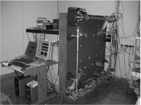
3 Experimental apparatus
The photograph of the experimental apparatus is shown in fig. 1. A thick and in side square granite slab supports the whole mechanical ring and defines the laser cavity reference frame. A reinforced concrete monument supports the granite table vertically, in order to measure the rotations around the horizontal direction. The laser resonator is a square optical cavity, 5.40 m in perimeter and 1.82 m2 in area, enclosed in a vacuum chamber entirely filled with the active medium gas. A fine movement of two opposite placed boxes along the diagonal of the square is also possible. This is provided by two piezoelectric transducers that allow the servo control of the laser cavity perimeter length .
4 Experimental results
The performances of the laser gyroscope as a tilt sensor have been tested in during a measurement run in strong wind weather conditions. In fig 2 is sketched the comparison between the RMS rotational noise and the RMS of the wind intensity. The action of the wind on the building is expected to induce a local tilt on the basement of the Virgo towers containing the super attenuators, so to introduce an excess noise in the inertial damping system.
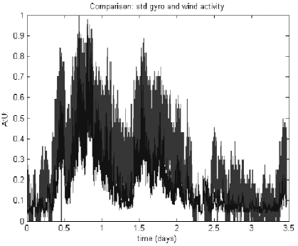
Fig. 3 shows the coherence calculated for the the rotational signal and the position sensor mounted on top the IP of the north-input and west input towers. A period of 2 hours of strong wind was selected from the data and the coherence function was calculated using the Welch periodogram/FFT method, with a time window of s and an overlapping of .

5 Discussion and conclusions
A laser gyroscope operating in a four mirrors ring cavity, in side, has been employed to monitor the local ground tilt of the Virgo central area. The detected rotation, superimposed on the Earth-rate constant bias, resulted to be correlated with the excess noise observed in control signals for the longitudinal traslations of the inverted pendulum (IP) control signals for the longitudinal traslations of the (IP) The coherence with the translational degrees of freedom in the plane of propagation of the gyrolaser beams is at the level of in the frequency range . This result supports the possibility of employing the gyroscope rotation signal to increase the stability of the active position control of the Virgo suspensions during severe weather conditions characterized by strong wind.
References
References
- [1] G. E. Stedman, Rep. Prog. Phys. 60-6, 615 (1997).
- [2] K.U. Schreiber, T. Klügel, A. Velikoseltsev, W. SchlÃŒter, G.E. Stedman, J.-P.R. Wells, Pure Appl. Geophys. 166, 1485 (2009).
- [3] K. U. Schreiber, T. Klügel, G. E. Stedman, J. Geophys. Res. 108, 2003 (.)
- [4] K. U. Schreiber, A. Velikoseltsev, M. Rothacher. T. Klügel, G. E. Stedman, D. Wiltshire, J. Geophys. Res. 109, (2004).
- [5] R. B. Hurst, G. E. Stedman, K. U. Schreiber, R. J. Thirkettle, R. D. Graham, N. Rabeendran, J.-P. R. Wells: J. Appl. Phys. 105, 113115 (2009).
- [6] G. Losurdo, D. Passuello and P. Ruggi, VIR-NOT-FIR-1390-318 1, April 10 (2006).
- [7] J. Belfi, N. Beverini, F. Bosi, G. Carelli, A. di Virgilio, E. Maccioni, M. Pizzocaro, F. Sorrentino, F. Stefani, Nuovo Cimento B 125, 557 (2010).