Coquet: a Coq library for verifying hardware
Abstract
We propose a new library to model and verify hardware circuits in the Coq proof assistant. This library allows one to easily build circuits by following the usual pen-and-paper diagrams. We define a deep-embedding: we use a (dependently typed) data-type that models the architecture of circuits, and a meaning function. We propose tactics that ease the reasoning about the behavior of the circuits, and we demonstrate that our approach is practicable by proving the correctness of various circuits: a text-book divide and conquer adder of parametric size, some higher-order combinators of circuits, and some sequential circuits: a buffer, and a register.
Introduction
Formal methods are widely used in the verification of circuit design, and appear as a necessary alternative to test and simulation techniques. Among them, model checking methods have the advantage of being fully automated but can only deal with circuit of fixed size and suffer from combinatorial explosion. On the other hand, circuits can be formally specified and certified using theorem provers [10, 9, 14]. For instance, the overall approach introduced in [9, 17] to model circuits in higher-order logic is to use predicates of the logic to express the possible behaviour of devices.
We present a study for specifying and verifying circuits in Coq. Our motivations are two-fold. First, there has been a lot of works describing and verifying circuits in logic in the HOL and ACL2 family of theorem provers. However, Coq features dependent types that are more expressive. The Veritas language experiment [10] hinted that these allow for specifications that are both clearer and more concise. We also argue that dependent types are invaluable for developing circuits reliably: some errors can be caught early, when type-checking the circuits or their specifications. Second, most of these works model circuits using a shallow-embedding: circuits are defined as predicates or functions in the logic of the theorem prover, with seldom, if any, way to reason about the devices inside the logic: for instance, functions that operate on circuits must be built at the meta-level [21], which precludes one from proving their correction. We define a data-type for circuits and a meaning function: we can write (and reason about) Coq functions that operate on the structure of circuits.
Circuit diagrams describe the wire connections between gates and have nice algebraic properties [5, 15]. While we do not prove algebraic laws, our library features a set of basic blocks and combinators that allows one to describe such diagrams in a hierarchic and modular way. We make precise the interconnection of circuits, yet, we remain high-level because we make implicit the low-level diagram constructs such as wires and ports. Circuit diagrams are also used to present recursive or parametric designs. We use Coq recursive definitions to generate circuits of parametric size, e.g., to generate a -bit adder for a given . Then, we reason about these functions rather than on the tangible (fixed-size) instantiations of such generators. Circuits modelled by recursion have already been verified in other settings [14, 17]. The novelty of our approach is that we derive circuit designs in a systematic manner: we structure circuits generators by mimicking the usual circuit diagrams, using our combinators. Then, the properties of these combinators allow us to prove the circuits correct.
We are interested in two kinds of formal dependability claims. First, we want to capture some properties of well-formedness of the diagrams. Second, we want to be able to express the functional correctness of circuits – the fact that a circuit complies to some specification, or that it implements a given function. Obviously, the well-formedness of a circuit is a prerequisite to its functional correctness. We will show that using dependent types, we can get this kind of verification for free. As an example, the type-system of Coq will preclude the user to make invalid compositions of circuits. Hence, we can focus on what is the intrinsic meaning of a circuit, and prove that the meaning of some circuits entails a high-level specification, e.g., some functional program.
Our contributions can be summarized as follows: we propose a new framework to model and verify circuits in Coq that allows to define circuits in a systematic manner by following usual diagrams; we provide tactics that allow to reason about circuits; we demonstrate that our approach is practicable on practical examples: text-book -bit adders, high-level combinators, and sequential circuits.
Outline.
In §1, we give a small overview of all the basic concepts underlying our methodology to present how the various pieces fit together. We present the actual definitions we use in §2. Then, in §3 and §4, we demonstrate the feasibility of our approach on some examples. We analyse some benefits of using a deep-embedding in §5. Finally, we compare our study to other related work in §6.
1 Overview of our system
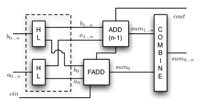
We give a global overview of the basic concepts of our methodology first, before giving a formal Coq definition to these notions in the next section. We take this opportunity to illustrate the use of our system to represent parametrized systems through the example of a simple -bit adder: it computes an -bit sum and a -bit carry out from two -bit inputs and a -bit carry in. The recursive construction scheme of this adder is presented in Fig. 1 (data flows from left to right), using a full-adder, i.e., a -bit adder, as basic building block.
Circuit interfaces.
Informally, we want to build circuits that relate input wires to output wires, where are integers. For instance, the door AND has two inputs and one output. However, using integers to number the wires does not give much structure: the -bit adder has input wires, this does not specify how they are grouped. Hence, we use arbitrary finite-types as indexes for the wires rather than using integers [11]. A circuit that relates inputs indexed by to outputs indexed by has type , where and are types. For instance, the full-adder, a circuit with three inputs and one output, has type , where is the disjoint sum (associative to the left) and is a singleton type. Hence, the -bit adder has type , where is a -ary disjoint sum.
Circuits combinators.
The -bit adder is made of several sub-components that are composed together. We use circuit combinators (or combining forms [19]) to specify the connection layout of circuits. For instance, in Fig. 1, the dashed-box is built by composing in parallel two HL circuits, that are then composed serially with a combinator that reorders the wires. These combinators leave implicit the connection points in the circuits, and focus on how informations flow through the circuit: the wire names given in Fig. 1 do not correspond to variables, and are provided for the sake of readability.
In our “nameless” setting, wires have to be forked and reordered using plugs: a plug is a circuit of type , defined using a map from to that defines how to connect an output wire (indexed by ) to an input wire (indexed by ). Since we use functions rather than relations, this definition naturally forbids short-circuits (two input wires connected to the same output wire).
Meaning of a circuit.
We now depart from the syntactic definitions of circuits to give an overview of their semantics. We assume a type of what is carried by the wires, for instance booleans () or streams of booleans (). Let be a circuit of type . The inputs (resp. outputs) of are a finite function of type (resp. of type ). The meaning of is a relation between and that we define by induction on . This is an abstract mathematical characterization, which may or may not be computational (we will come back to this point later).
Abstracting from the implementation.
The meaning of a circuit is defined by induction on its structure: this relation may be complex and may give informations about the internal implementation of a circuit. Thus, we want to move from the definition of this relation, for instance, to give high-level specifications, or to abstract their behavior. These abstractions can be expressed through the following kind of entailment [17]:
We use data-abstraction [17] to be more elegant. Indeed, a value of type is isomorphic to a value of type (where is the type of integers from to ). We use type-isomorphisms to give tractable specifications for circuits: we prove that the parametric -bit adder depicted in fig 1 implements the addition with carry function on .
2 Formal development
We now turn to define formally the concepts that were overviewed in the previous section. We use Coq type-classes to structure our development and parametrize code.
2.1 Circuit interfaces
We use arbitrary finite types (types with finitely many elements) as interfaces for the circuits, i.e., as indexes for the wires. One can create such finite types by using the disjoint-sum operator and the one-element type . This construction can be generalized to -ary disjoint sums written sumn A n, for a given A. However, using a single singleton type for all wires can be confusing: there is no way to distinguish one from another, except by its position in the type (which is frustrating). Hence, we use an infinite family of singleton types where is a tag. Circuits are parametrised by some tags, which allows the Coq type-system to rule out some ill-formed combinations. This tagging discipline allows to easily follow circuit diagrams to define circuits in Coq, without much room for mistakes.
Finite types are defined as a class Fin A that packages a duplicate-free list of all the elements of the type A, defined along the lines of [8].
2.2 Type isomorphisms
We use type-isomorphisms as “lenses” to express the specification of circuits in user-friendly types, without loss of information. In a nutshell, we define in Coq an isomorphism between two types and as a pair of functions and that are proved to be inverse of each other. We use the notation for an isomorphism between and , and we define some notations for operations (or instances)that allow one to build such isomorphisms in Fig. 2. The most important instance state the duality between disjoint-sums in the domain of the finite functions to a cartesian product.
|
Class Iso_Props {A B: Type} (I : Iso A B):= {
iso_uniso : (x : B), iso (uniso x) = x;
uniso_iso : (x : A), uniso (iso x) = x}.
|
2.3 Plugs
Rewiring circuits of type are defined by mapping output wires indexed by to input wires indexed by . We define plugs using usual Coq functions to get small and computational definition of maps. (Note that, since we map the indexes of the wires, there is no way to embed an arbitrary function inside our circuits to compute, e.g., the addition of the value carried by two input wires.)
We give three examples: (a) is a circuit that forgets its first input (types must be read bottom-up on diagrams); (b) is a circuit that duplicates its inputs; (c) implements some re-ordering and duplication of the wires. (We leave implicit the associativity of wires on the diagrams.)
| (a) | (b) | (c) |
A possible implementation for (a) is fun x inr x and (b) can be implemented as fun x match x with inl e e | inr e e end. If the type of the circuit gives enough informations, like the examples above, it is possible to define such plugs using proof-search. Indeed, plugs that deal with the associativity of the wires, or even re-orderings, are completely defined by their type, and we use tactics to write the map between wires (it amounts to some case splitting and little automation). Hence, in the formal definition of circuits, we omit the plugs that deal with associativity or re-orderings of the wires, not only for the sake of readability, but also because we do so in the actual Coq code: we leave holes in the code (thanks to the Coq Program feature) that will be filled automatically.
2.4 Abstract syntax
In the following, we use some basic gates from which all other circuits are defined. Hence, we parametrize the definition of circuits by the type of the gates:
The Fig. 3 presents the dependent type that models circuits, as defined in Coq. This abstract syntax is strongly typed: it ensures that circuits built using the provided combinators are well-formed: dimensions have to agree, and it is not possible to connect circuits in the wrong direction. (Note that this is not anecdotal: if we were to describe circuits with ports and wires, ensuring these properties would require some boilerplate.) We denote serial composition (Ser) with the infix symbol, and parallel composition (Par) with . (Note that these definitions do not deal with what transit in the wires.)
2.5 Structural specifications
Let be the type of what is carried in the wires. We now define the meaning relation for circuits. For a given circuit of type , we build a relation between two functions of type and . We define several operations on such functions, in order to express the meaning relation in a legible manner:
We define the semantics of a given set of basic gates tech: Techno by defining instances of the following type-class, (typically, one instance for the boolean setting, and one instance in the stream of boolean setting):
The meaning relation for circuits is generated by this parameter and rules for each combinator. These rules are presented on Fig. 4 using inference rules rather than the corresponding Coq inductive, for the sake of readability.
| KSer KPar KPlug KLoop |
2.6 Abstractions
The meaning relation defines precisely the behavior of a circuit, but cannot be used as it is. First, it may be too precise, e.g., with some internal details leaking, or imposing constraints between the inputs and the outputs of a circuit that are not relevant from an external point of view. Second, it defines a constraint between the inputs and outputs of a circuit as a relation between two functions and , which is not user-friendly. In his book [17], Melham defines two kinds of abstractions that are relevant here: behavioral abstraction (expressed through the logical entailment of a weak specification by the meaning relation) and data-abstraction (when the specification is expressed in terms of higher-level types than the above function types).
We combine these two notions to specify that a given circuit realises a specification up-to two type isomorphisms, and to get more concise specifications, we also define the fact that a circuit implements a function f up-to isomorphisms:
2.7 Atoms and modular proofs
We develop circuits in a modular way: to build a complex circuit, we define a functor that takes as argument a module that packages the implementations of the sub-components, and the proofs that they meet some specification. This means that our proofs are hierarchical: we do not inspect the definition of the sub-components when we prove a circuit. These functors can then be applied to a module that contains a set of basic doors (of type Techno) and its meaning relation (of type Technology_spec).
3 Proving some combinatorial circuits
In this section, we focus on acyclic combinational circuits, and implements some arithmetic circuits. We assume a set of basic gates (AND, XOR among others, that can all be defined and proved correct starting from NOR only). Wires carry booleans, i.e., the meaning relation is defined on booleans for the basic gates. We first illustrate our proof methodology on a half-adder. Then, we present operations on -bits integers, that will be used to specify -bit adders.
3.1 Proving a half-adder
A half-adder adds two -bit binary numbers together, producing a -bit number and a carry out. However, they cannot be chained together since they have no carry in input. We present a diagram of this circuit, along with its formal definition, in Fig. 5. The left-hand side of the following Coq excerpt is the statement we prove: the circuit HADD implements the function hadd on booleans (defined as \fun(a,b).(a \xorb b, a && b), where is the boolean exclusive-or, and is the boolean and) up-to isomorphisms (we use the notations from Fig. 2 for isos). The Coq system ask us to give evidence of the right-hand side.
|
Context a b s c : string. (*section variables*)
Definition HADD : () () :=
Fork2 () (XOR a b s & AND a b c).
|
We have developed several tactics that help to prove this kind of goals. First, we automatically invert the derivation of the meaning relation in the hypothesis H, following the structure of the circuit, to get rid of parallel and serial combinators. This leaves the user with one meaning relation hypothesis per sub-component in the circuit (plugs included). Second, we use the type-class Implement as a dictionary of interesting properties. This allows one to make fast-forward reasoning by applying implements in any hypothesis stating a meaning relation for a sub-component. The type-class resolution mechanism will look for an instance of Implement for this sub-component, and transform the “meaning relation” hypothesis into an equation. (Note that at this point, the user may have to interact with the proof-assistant, e.g., to choose other Implement instances than the one that are picked automatically, but in many cases, this step is automatic.) At this point, the goal looks like the left-hand side of the following excerpt:
|
I: \bool * \bool, O: \bool * \bool,
M : (\bool * \bool) * (\bool * \bool),
H0: M = (fun x (x,x)) I
H1: fst O = uncurry \xorb (fst M)
H2: snd O = uncurry \andb (snd M)
==================
O = hadd I
|
Third, we move to the right-hand side of the excerpt: we massage the goal to make some iso commute with the left, right and app operations, in order to generalize the goal w.r.t. the isos. (Note that the user may be required to interact with Coq if different isos are applied to the same term in different equations.) Finally, the proof context deals only with high-level data-types, and functions operating on these. The user may then prove the “interesting” part of the lemma.
3.2 -bits integers
From now, we use a dependently typed definition of -bits integers, along the lines of the fixed-size machine integers of [16]. We omit the actual definitions of functions when they can be infered from the type. In the following, we prove that various (recursive) circuits implement the carry_add function (that adds two -bit numbers and a carry).
3.3 Two specifications of a -bit adder
A full-adder adds two -bit binary numbers with a carry in, producing a -bit number and a carry out, and is built from two half-adders. We present a diagram of this circuit, along with its formal definition in Fig. 6.
|
Context a b cin sum cout : string.
Program Definition FADD :
() () :=
(ONE & HADD a b "s1" "c1")
… (* associativity plug *)
(HADD cin "s1" sum "c2" & ONE )
… (* associativity plug *)
(ONE & OR "c2" "c1" cout).
|
From this circuit, we can derive two specifications of interest. First, the meaning of the full-adder can be expressed in terms of a boolean function, that mimics the truth-table of the circuit. Second, we can prove that this circuit actually implements the carry_add function up-to isomorphism. Both these specifications are proved using the aforementioned tactics, only the interesting parts differ.
|
Instance FADD_2 : Implement
() (* iso on inputs *)
() (* iso on outputs *)
FADD (fun (c,(x,y))
\tabcarry_add 1 x y c).
|
3.4 Ripple-carry adder
We present in Fig. 7 the formal definition of the ripple-carry adder from Fig. 1 (we omit the rewiring plugs). This definition is based on two new circuits to split wires, and combine them. Indeed, to build a -bit adder, the lowest-order wire of each parameter is connected to a full-adder, while the high-order wires of each parameter are connected to another ripple-carry adder. Conversely, the wires corresponding to the sum must be combined together. We use two plugs to define the HL and the COMBINE circuits.
Then, we prove that these functions on wires implements their counterparts on words. These gates are then easily combined two-by-two to build HIGHLOWS and COMBINES that works with two sets of wires at the same time to get more economical designs (i.e., designs with less sub-components).
Finally, we prove by induction on the size of the circuit that it implements the high-level carry_add addition function on words. (Note that this is a high-level specification of the circuit: the carry_add function is not recursive and disclose nothing of the internal implementation of the device.) This boils down to the proof of lemma add_parts.
This design is simple (a linear chain of -bit adders) and slow (each full-adder must wait for the carry-in bit from the previous full-adders). In the next subsection, we address the case of a more efficient adder, which is incidentally more complicated, and a better benchmark for our methodology.
3.5 Divide and conquer adder
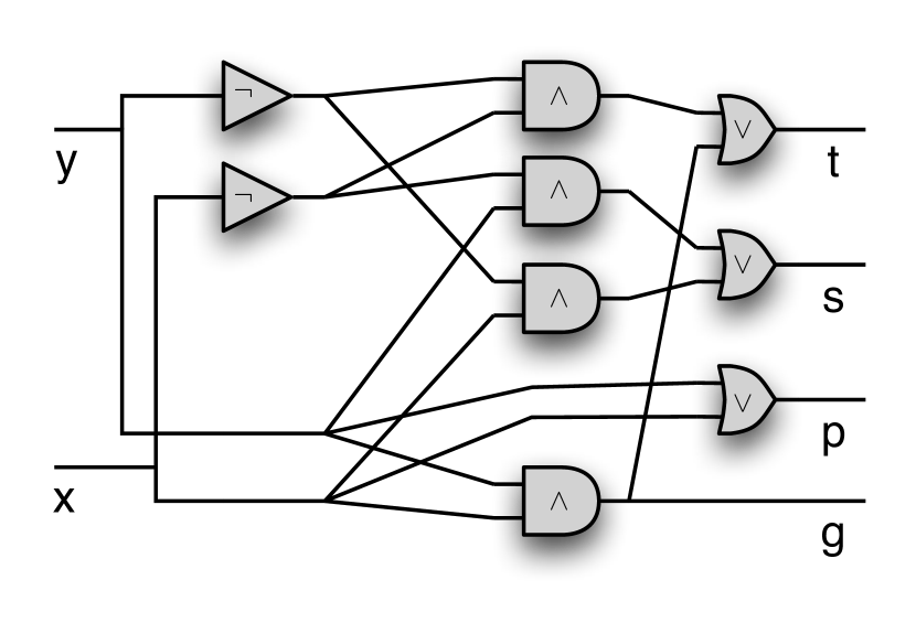
A text-book [1] solution to improve on the delay of the ripple-carry adder is to use a divide and conquer scheme, and to compute both the sum when there is a carry in, and the sum when there is no carry in. It is then possible to compute at the same time the sum for the high-order bits, and the sum for the low order bits. Hence, we build a circuit that computes four pieces of data: (resp. ), the -bit sum of the inputs, assuming that there is no carry in (resp. assuming that there is a carry in); the carry-propagate bit (resp. the carry-generate bit), which is true when there is a carry out of the circuit, assuming that there is a carry in (resp. that there is no carry in).
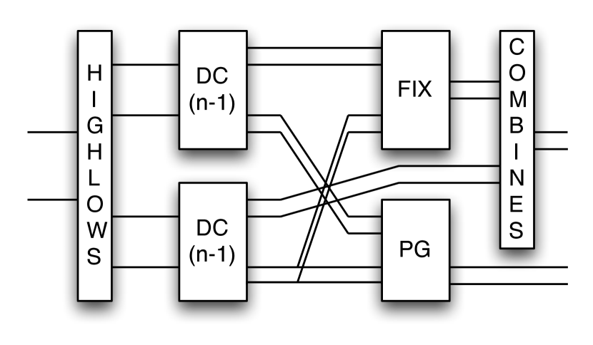
We provide a diagram in Fig. 8 that depicts the base case and the recursive case, but we omit the actual Coq implementation, for the sake of readability. We prove that this circuit implements the following Coq function:
Again, this is a high-level specification w.r.t. the definition of the circuit: it does not disclose how the circuit compute its results (for instance, the dc function is not recursive). In a nutshell, the circuit computes in parallel the 4-uple of results for the high-order and low-order part of the inputs. Then, the propagate and generate bits for both parts can be combined by the PG circuit to compute the propagate and generate bits for the entire circuit. In parallel, the FIX circuit is made of two -bit multiplexers (easily defined with a fixpoint using -bit multiplexers), and update the high-order parts of the sum, w.r.t. the propagate and generate carry-bits of the low-order adder.
|
|
4 Sequential circuits: time and loops
While we have focused our case studies on combinational circuits, our methodology can be applied to sequential circuits, with or without the loops that were allowed in the syntax of circuits in §2.4. In this section, the wires carry streams of booleans (of type nat \bool), and we assume a basic gate DFF that implements the pre function (in the particular case of booleans):
A buffer.
A DFF delays one wire by one unit of time; a FIFO buffer generalize this behavior in two dimensions, by chaining layers of DFF one after another. This circuit is simple, but is a good example for the use of high-level combinators.
These combinators capture the underlying regularity in some common circuit pattern, for instance replicating a sub-component in a serial or parallel manner.
We prove that the COMPOSEN combinator implements a higher-order iteration function, up-to isomorphism: if CELL implements a given function f, then COMPOSEN k implements the iteration of f. Respectively, we prove that the MAP circuit implements the higher-order map function on vectors. Hence, a FIFO buffer in one-line, and we prove that it implements the function below.
The proof of this specification relies on the above useful isomorphism between groups of wires that carries streams of booleans, and a stream of vectors of booleans. The proof that the circuit implements a function on streams is done in the same fashion as the proofs from the previous section.
A memory element.
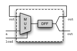
Our next goal is to demonstrate how we deal with state-holding structures. Hence, we turn to the implementation of a -bit memory element, as implemented in Fig. 9.
| ⬇ Context a load out : string. Program Definition REGISTER: := @Loop (… MUX2 a out load "in_dff" DFF "in_dff" out Fork2 ). |
|
The register is meant to hold -bit of information through time, which does not fit nicely in the Implement framework (we cannot easily express the meaning of the register in terms of a stream transformer). Hence, we use a relational specification through the use of Realise:
Here, the state of the register is stored inside the history of the stream (the previous values that were taken by the output). While we do not advocate that this is the nicest way to reason about state holding devices, we were able to prove this specification in the same fashion as the previous combinatorial devices. We leave more thorough investigation of state-holding devices to future work.
5 Interesting corollaries
We now turn on to investigate some interesting consequences of the use of a concrete data-type to represent circuit. First, we prove that the behavior of combinatorial circuits without delay can be lifted to the stream setting. Second, we build some functions (or interpretations [2]) that operates on circuits.
5.0.1 Lifting combinatorial circuits.
The meaning relation is parametrized by the semantics of the basic gates. This can be put to good use to prove the functional correction of some designs in the boolean setting, and then, to mechanically lift this proof of functional correction to the boolean stream setting (for the same set of gates). For instance, if a loop-less and delay-less circuit implements a function f in the boolean setting, we can prove that the very same circuit implements the function Stream.map f in the boolean stream setting.
Simulating and checking designs.
One key feature of our first-order encoding of circuits in Coq is that it allows to check designs by simulation before attempting to prove them. This verification is done on the same definition than the one which will be proved later, allowing a seamless approach. While simulation cannot be done on circuits parametrized by a size, this remains a valuable help to avoid dead-ends. We define a simulation function sim that works on loop-free circuits, if the user provide a computational interpretation of each basic gate. For instance, it allows to simulate the adders of §3.
5.0.2 Delay and pretty-printing.
Using the same ideas, we can build functions that compute the list of gates of circuits (with or without loops), or compute the length of the critical path in combinatorial circuits. While this is more anecdotal, and less directly useful than the previous simulation function, these functions are still interesting: one could, for instance, prove that some complex designs meet some time (or gate-count) complexity properties. (Note that is the only place where we exploit the finiteness of types.)
6 Comparisons with related works
6.0.1 Verifying circuits with theorem provers.
There has been a substantial amount of work on specification and verification of hardware in HOL. In [9, 17], HOL is used as a hardware description language and as a formalism to prove that a design meets its specification. They model circuits as predicates in the logic, using a shallow-embedding that merges the architecture of a circuit and its behavior. Building on the former methodology, [21] defines a compiler from a synthetisable subset of HOL that creates correct-by-construction clocked synchronous hardware implementations of mathematical functions specified in HOL. This methodology allows the designer to focus on high-level abstraction instead of reasoning and verifying at the gate level, admitting the existence of some base low-level circuits (like the addition on words [13]). By contrast, our work complement their behavioral “correct by design” synthesis from a subset of the high-level language of the theorem-prover with structural verification of circuits.
In the Boyer-Moore theorem prover (untyped, quantifier-free and first-order), Brock and Hunt proved the correctness of functions that generate correct hardware designs. They studied the correctness of an arithmetic and logic unit, parametrised by a size [14]. This verified synthesis approach was used to verify a microprocessor design [4]. While our proofs are not as automated, and our examples are less ambitious, we are able to prove higher-order circuits. Moreover, the dependent-types we use are helpful when defining complex circuits.
In Coq, Paulin-Mohring [18] proved the correction of a multiplier unit, using a shallow-embedding similar to the methodology used in HOL: circuits are modelled as functions of the Coq language. More recently, [6] investigated how to take advantage of dependent types and co-inductive types in hardware verification: they use a shallow embedding of Mealy automata to describe sequential circuits. By contrast with both works, we use a deep-embedding of circuits in Coq, that makes explicit the definition of circuits. We still need to investigate the examples of sequential circuits studied in these papers.
6.0.2 Algebraic definitions of circuits.
Circuit diagrams have nice algebraic properties. Lafont [15] studied the algebraic theory of boolean circuits and Hinze [12] studied the algebra of parallel prefix circuits. Both settings are close to ours: however the former focused on the algebraic structure of circuits, while the latter defined combinators that allows to model (and prove correct using algebraic reasoning) all standard designs of a restricted class of circuits.
6.0.3 Functional languages in hardware design.
Sheeran [20] made a thorough review of the use of functional languages in hardware design, and of the challenges to address. Our work is a step toward one of them: the design and verification of parametrized designs, through the use of circuit combinators. Lava [2] is a language embedded in Haskell to describe circuits, allowing one to define parametric circuits or higher-order combinators. While much of our goals are common, one key difference is that our encoding of circuits in Coq avoid the use of bound variables (we use only combinators). Moreover, we use dependent types, that are required to deal precisely with parametric circuits. Finally, we prove the correctness of these parametric circuits in Coq, while verification in Lava is reduced to the verification of finite-size circuits.
7 Conclusion and future works
We have presented a deep-embeding of circuits in the Coq proof-assistant that allows to build and reason about circuits, proving high-level specifications through the use of type-isomorphism. We have demonstrated that dependent types are useful to prove automatically some well-formedness conditions on the circuits, and helps to avoid time consuming mistakes. Then, we proved by induction the correctness of some arithmetic circuits of parametric size: this could not have been possible without mimicking the structure of the usual circuit diagrams to define circuit generators in Coq. The formal development accompanying this paper is available from the authors web-page [3].
In the immediate future, we plan to continue the case studies described in §3. In particular, we would like to investigate how to construct parallel prefix circuits in our framework [12, 20], and to investigate combinational multipliers. In the more distant future, it would be interesting to study some front-ends to automatically generate some circuits: this could range to the reduction of the boiler-plate inherent to the definition of plugs, to the compilation of circuits from automaton. A major inspiration on behavioral synthesis is the work of Ghica [7]. We also look forward to study how our methodology applies to other settings that booleans or streams of booleans. For instance, if we move from booleans to the three-valued Scott’s domain (unknown, true, false), we may interpret circuits in the so-called constructive semantics. We also hope that some of our methods could be applied to the probabilistic setting.
References
- [1] A. V. Aho and J. D. Ullman. Foundations of Computer Science. Computer Science Press, W. H. Freeman and Company, 1992.
- [2] P. Bjesse, K. Claessen, M. Sheeran, and S. Singh. Lava: Hardware Design in Haskell. In Proc. ICFP, pages 174–184. ACM Press, 1998.
- [3] T. Braibant. Coquet: a coq library for verifying hardware. http://sardes.inrialpes.fr/~braibant/coquet, June 2011.
- [4] B. Brock and W. A. Hunt Jr. The DUAL-EVAL Hardware Description Language and Its Use in the Formal Specification and Verification of the FM9001 Microprocessor. Formal Methods in System Design, 11(1):71–104, 1997.
- [5] C. Brown and G. Hutton. Categories, allegories and circuit design. In Proc. LICS, pages 372–381. IEEE Computer Society, 1994.
- [6] S. Coupet-Grimal and L. Jakubiec. Certifying circuits in type theory. Formal Asp. Comput., 16(4):352–373, 2004.
- [7] D. R. Ghica. Geometry of synthesis: a structured approach to VLSI design. In Proc. POPL, pages 363–375, 2007.
- [8] G. Gonthier and A. Mahboubi. An introduction to small scale reflection in Coq. Journal of Formalized Reasoning, 3(2):95–152, 2010.
- [9] M. Gordon. Why higher-order logic is a good formalisation for specifying and verifying hardware. Technical Report UCAM-CL-TR-77, Cambridge Univ., Computer Lab, 1985.
- [10] F. K. Hanna, N. Daeche, and M. Longley. Veritas: A specification language based on type theory. In Hardware Specification, Verification and Synthesis, LNCS, pages 358–379. Springer, 1989.
- [11] J. R. Harrison. A HOL theory of Euclidean space. In J. Hurd and T. Melham, editors, Proc. TPHOLs 2005, volume 3603 of LNCS, pages 114–129. Springer, 2005.
- [12] R. Hinze. An Algebra of Scans. In Dexter Kozen and Carron Shankland, editors, MPC, LNCS, pages 186–210. Springer, 2004.
- [13] J. Iyoda. Translating HOL functions to hardware. Technical Report UCAM-CL-TR-682, University of Cambridge, Computer Laboratory, April 2007.
- [14] W. A. Hunt Jr. and B. Brock. The Verification of a Bit-slice ALU. In Miriam Leeser and Geoffrey Brown, editors, Hardware Specification, Verification and Synthesis, volume 408 of LNCS, pages 282–306. Springer, 1989.
- [15] Y. Lafont. Towards an algebraic theory of boolean circuits. Journal of Pure and Applied Algebra, 184:2003, 2003.
- [16] X. Leroy. A formally verified compiler back-end. Journal of Automated Reasoning, 43(4):363–446, 2009.
- [17] T. Melham. Higher Order Logic and Hardware Verification, volume 31 of Cambridge Tracts in Theoretical Computer Science. Cambridge University Press, 1993.
- [18] C. Paulin-Mohring. Circuits as Streams in Coq: Verification of a Sequential Multiplier. In TYPES, pages 216–230, 1995.
- [19] M. Sheeran. FP, A Language for VLSI Design. In LISP and Functional Programming, pages 104–112, 1984.
- [20] M. Sheeran. Hardware Design and Functional Programming: a Perfect Match. J. UCS, 11(7):1135–1158, 2005.
- [21] K. Slind, S. Owens, J. Iyoda, and M. Gordon. Proof producing synthesis of arithmetic and cryptographic hardware. Formal Asp. Comput., 19(3):343–362, 2007.