Thermoelectric properties of molecular nanostructures
Abstract
We use the concept of resonant tunneling to calculate the thermopower of molecular nanosystems. It turns out that the sign of the thermovoltage under resonant tunneling conditions depends sensitively on the participating molecular orbital, and one finds a sign change when the transport channel switches from the highest occupied molecular orbital to the lowest unoccupied molecular orbital. Comparing our results to recent experimental data obtained for a BDT molecule contacted with an STM tip, we observe good agreement.
I Introduction
Studies of the origin of a voltage or current in nanosystems in the presence of a temperature gradient are an extremely interesting and promising area in the field of nanotechnologies 1 ; 2 ; 3 . There are several important possible future applications in several areas of devices, among them the development of nanothermosensors (see for example 10 ), which is especially urgent for a number of technological processes and for research in biology concerning the functioning of life.
However, different from the classical description of thermoelectric phenomena, which is already challenging enough, the necessity to apply strictly quantum-mechanical methods in the realm of nano-objects makes the whole problem an extremely difficult one, and a proper theory for studying transport phenomena in the most general setup does not yet exist. However, for the description of most experimental realizations of thermoelectric transport through nanon-structures, one can fortunately make some simplifying assumptions. Usually, one can consider the system to consist of two metallic structures, which are typically very good conductors and which we will call leads, that are spatially separated. Hence, there will be no current flowing between the leads. Placing an active element like a molecule between these leads will thus induce a transport path and, when voltage or temperature differences between the leads are imposed, to thermoelectric phenomena overview . The coupling of the molecule and the leads will be of tunneling type, i.e. one can usually assume that this coupling is rather weak.
Although this setup seems rather straightforward, its actual experimental realization is by no means trivial. In particular, a good control over if a molecule is attached to both leads at all and how good the coupling to the leads is, is very hard to obtain 2 . Furthermore, when using two extended leads on a common substrate, the introduction of temperature gradients poses a further challenge. A certain breakthrough along these lines has been achieved recently by using an STM tip to controlled pick molecules on a metal surface and generate well-defined break junctions. Here, certain control over the coupling between the molecule and the leads can be performed by moving the tip, and a temperature gradient can easily be applied by heating the metal while keeping the tip a fixed temperature 2 .
In the present paper, we develop a non-equilibrium description of the stationary thermotransport through such a nanostructure, using the idea of resonant tunneling. The model is rather simple, but can be solved analytically, and the theoretical results can be directly compared with experimental data. We find a rather good agreement, which we believe is in favor of this simple and straightforward model.
II Resonant tunneling with applied temperature gradient
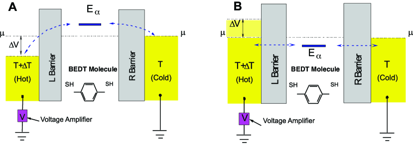
Resonant electron tunneling of particles through a system of double potential barriers is very sensitive to a position of electronic states in a quantum well 4 . This circumstance can be used for the effective control of the tunneling process. As a model of a double-barrier tunneling system, we assume the structure with the energy profile shown schematically in Fig. 1 5 ; 6 ; 7 ; 8 ; 9 . The Hamiltonian describing the tunneling of electrons through such a structure can be chosen in the form
| (1) |
The first term of this Hamiltonian is
| (2) |
It describes electrons in the left electrode (source) and in the right (drain). Because we are not interested in the detailed properties of the leads, we assume that these charge carriers can be taken to be quasi-particles, and respectively are the creation (annihilation) operators for these quasi-particle in source respectively drain. The dispersions are in the same spirit given by , where denote the effective masses for the left and right lead. We will assume in the following for simplicity.
The Hamiltonian describes the electronic states in the nano-object. It can be written in the form
| (3) |
where labels the single-particle levels of the molecule, and denotes possible interactions. The energy in the well depends on the applied bias and can be written as , where is the bare energy of the resonant state in the quantum well, the potential drop across the molecule, the elementary charge and a factor depending on the profile of the potential barriers (for identical barriers, ). Finally, the Hamiltonian describing the tunneling of electrons through the barriers has the conventional form
| (4) |
Here, is the matrix element of tunneling from source respectively drain to and from the molecule. As usual, we assume that both are the same and that they also do not depend on the applied bias.
When we apply a constant external bias across the system, a nonequilibrium steady-state electron distribution will result. We assume that the electron distribution functions in the electrodes (source, drain) are equilibrium ones, i.e. Fermi functions, due to the large volumes of these reservoirs, but their chemical potentials and temperatures can be different. The chemical potentials usually encode a voltage drop across the nano-region, hence in our model , and .
The simple setup of the system in Fig. 1 makes the evaluation of nonequilibrium properties comparatively simple.The important quantity entering all formula is the density of states (DOS) for the local level in the presence of the leads Meir_Wingreen . To calculate it, we need the retarded Green’s function Mahan , from which we can obtain the DOS as
The electron distribution function in the quantum well is essentially nonequilibrium. It can be determined from the condition of equality of the tunneling currents through the source and the drain. Then the distribution function has the form
| (5) | |||||
| (6) |
where and are the tunneling rates for source (L) and drain (R), given by the expressions Meir_Wingreen
| (7) | |||||
| (8) |
and and are the quasi-particle distribution functions in the source and the drain, respectively. They have Fermi-Dirac form and read temperature difference
where is the Boltzmann constant, and are temperatures in the source and the drain, respectively.
III Double barriers thermostructures for resonant tunneling
With the above formula for the distribution function, one can straightforwardly evaluate physical quantitites. For example, the occupancy of the molecule can be determined with the help of expression 5
Moreover, the net current between source and drain through the molecule is given by the equation 7 ; Meir_Wingreen
| (9) |
where . Since we assume that the contacts are of tunnel type, the transition rates , are exponentially dependent on the barrier widths and heights. Correlation effects between the electrons in a nano-structure encoded in can be taken into account by means of , too Meir_Wingreen , and will in general dramatically modify the properties goldhaber-gordon ; cronenwett . The theoretical description of this situation is at present possible in the linear response regime only (see Mravile and Ramsak ramsak for an overview).
At this point one can only proceed analytically by assuming a low transparency of the barriers, i.e. , and a simple energy level structure, for example a quasi-particle description of the electronic structure based on first-principle methods. The density of states then only depends on the energy structure of the nano-structure via
where is Dirac’s function and a weighting factor for the energy level . For the current we then obtain the formula
| (10) |
The distribution functions are exponentially dependent on the energy . Thus, when , where denotes a neighboring molecular orbital, there will be one particular energy for which is minimal. With respect to this orbital, transport through all other will be exponentially suppressed, hence we need to keep only this particular orbital in the calculations. In this approximation, 10 can be reduced to the form , respectively, for small but finite ,
| (11) |
According to our definition, is one of the energy levels of a BDT molecule which has the smallest distance from the chemical potential, which will either be the highest occupied molecular orbital (HOMO) or the lowest unoccupied molecular orbital (LUMO). That molecule level is, as noted before, shifted by the voltage by a value . For an asymmetric barriere we have . Note that since the tunneling matrix elements for source and drain were chosen to be the same, this expression remains well-defined in the limit . The solution of 11 then becomes
| (12) |
where as final step we also assumed that for energies close to .
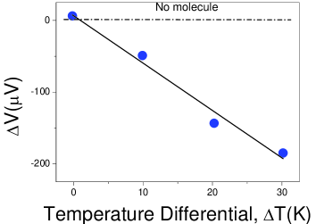
Our 12 can now be compared with experimental data. In particular, such a comparison with the experiments on BDT with STM 2 results in . Acording to our setup in Fig. 1 this means that . Thus, the energy level seen in experiment is a HOMO, i.e. the condition shown in Fig. 1B. In fact, the conductivity of the tunneling structure is determined by holes. The detailed comparison of the thermo-voltage dependence on is demonstrated in Fig. 2. In the case of , 12 can be approximated by a linear relation
| (13) |
From the comparison with the experiment, we get meV.
To study the dependence of thermoelectric effects on the distance between substrate surface (source) and STM tip (drain), let us consider our double-barrier system as a simple resistor network. In this case, 11 and 10 can be reduced to
| (14) |
with an externally imposed current , where is the external impedance of the whole measurement system. We note that if the conditions and are valid, 14 can be rewritten as
| (15) |
where . In the case of an open circuit , we have , and 13 and 15 are the same. The quantities and entering are exponentially dependent on the barrier widths, i.e. we can approximate them as
| (16) |
where are the widths of left and right barriers, respectively, and depends on the barrier height. The barrier lengths can in the experimental setup be controlled by moving the STM tip 2 . Finally, relation 15 can be written in the form
| (17) |
where
Note that the total distance between source and drain is , where is the diameter of the molecule BDT.
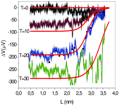
This theoretical length dependence of the thermoelectrical voltage can be compared with experimental data 2 . The result is shown in Fig. 3. In our calculations, we fixed the parameters by obtaining the best fit for K, resulting in nm, nm, nm-1, , V/K. The remaining curves for the other temperatures were then calculated using these model parameters. The general agreement between theory and experiment is very good, only at larger we observe stronger deviations. Since our model is comparatively simple and naturally contains various assumptions, such a deviation is not surprising but to be expected. It can be attributed to various sources, ranging from neglected barrier height fluctuations to influence of additional molecular orbitals or even molecular vibrations ramsak ; ora ; sergei .
IV Summary
A theoretical description of transport through nano-structures makes a full quantum-mechanical description of the system mandatory. In contrast to bulk materials, one cannot even adopt some semi-classical approach based on e.g. Boltzmann equations here. Since one also needs to take into account the inherent non-equilibrium situation in many cases, solving this problem has become one of the most challenging tasks in modern condensed matter theory. A certain simplification arises when one can use the concept of resonant tunneling. This is usually possible in weakly contacted nano-objects like molecules, and allows to quite accurately describe the thermoelectric phenomena in these systems.
We have presented here the calculation of thermotransport through a BEDT molecule contacted with a metallic substrate and a STM tip via generation of a break junction 2 . In the limit of only weakly transparent barriers we were able to obtain an explicit formula for the voltage drop across the molecule as function of temperature difference between substrate and tip. We found that the experimental data are well described by a resonant tunneling process involving the HOMO of the molecule.
Modelling the dependence of tunneling rates between the molecule and substrate/tip with a simple exponential ansatz, we were furthermore able to give a closed expression for the dependence of the thermoelectric effect on the distance between tip and substrate. The comparison to experiment could be done by extracting the relevant model parameters from one set of data for a fixed K only, reproducing the remaining curves with good accuracy. Thus, our formula describes very accurately the transport through such a nano-object, provided the coupling to the leads is sufficiently weak.
There are, of course, several severe simplifications in the model. The possibly most relevant is the neglect of interaction effects on the molecule, as well as molecular vibrations and also vibrations of the whole molecule between the contacts. These additional features can be taken into account ramsak ; sergei , and under very simplifying assumptions also solved analytically sergei . We therefore believe that such results, may they seem simple or straightforward, are nevertheless very important steps to enhance our knowledge about transport through nano-structures and can actually also serve as benchmarks to test more elaborate theoretial tools.
Acknowledgements.
We acknowledge financial support by the Deutsche Forschungsgemeinschaft through project PR 298/12 (T.P. , S.K. and V.K.) . S.K. furthermore thanks the Institute for Theoretical Physics of the University of Göttingen and T.P. the Bogolyubov Institute for Theoretical Physics of the NASU in Kiev for their support and hospitality during the respective visits.S.K. is grateful for a financial support of the SASIIU of the project Ukraine - Republic of Korea.References
- (1) M. Paulsson et al., Phys. Rev. B 67, 24103(R) (2003).
- (2) P. Reddy et al., Science, 315, 1568 (2007).
- (3) J.R. Prance et al., Phys. Rev. Lett. 102, 146602 (2009).
- (4) V. Ermakov, S. Kruchinin, A. Fujiwara, Proceedings NATO ARW “Electron transport in nanosystems”, edited by J. Bonca and S. Kruchinin, Springer, Berlin, 2008, p. 341-349.
- (5) L.P. Kouwenhoven et al in Mesoscopic Electron Transport (Proceedings of the NATO Advanced Study Institute) L. Sohn, L.P. Kouwenhoven and G. Schön, eds. (Kluwer, Dordrecht, Netherlands, 1997)
- (6) H. Grabert, M.H. Dovoret, Single Charge Tunneling (Plenum, New York, 1992).
- (7) V.N. Ermakov, Physica E 8, 99 (2000).
- (8) A.S. Alexandrov, A.M. Bratkovsky, Phys. Rev. B 67, 235312 (2003).
- (9) V.N. Ermakov, E.A. Ponezha, J. Phys. Condens. Mater 10, 2993, (1998).
- (10) A.S. Alexandrov, A.M. Bratkovsky, P.E. Kornilovitch, Phys. Rev. B 65, 155209 (2002).
- (11) V. Ermakov, S. Kruchinin, H. Hori, A. Fujiwara, Int. J. Mod. Phys. 21, 18279 (2007)
- (12) Y. Meir Y and N.S. Wingreen, Phys. Rev. Lett. 68, 2512 (1992).
- (13) Mahan G D 2000 Many-Particle Physics (Kluwer Academic, 3rd edition)
- (14) D. Goldhaber-Gordon et al., Nature 391, 156 (1998).
- (15) S. Cronenwett, T Oosterkamp and L.P. Kouwenhoven, Science 281, 540 (1998).
- (16) J. Mravlje and A. Ramšak, in Proceedings of the NATO Advanced Research Workshop on Physical properties of nanosystems, J. Bonca and S. Kruchinin, eds. (Springer 2010), p. 45
- (17) O. Entin-Wohlman, Y. Imry and A. Aharony, Phys. Rev. B 82, 115314 (2010).
- (18) S. Kruchinin and T. Pruschke, arXiv:1108.4526 (2011).