Microfluidic propulsion by the metachronal beating of magnetic artificial cilia: a numerical analysis
Abstract
In this work we study the effect of metachronal waves on the flow created by magnetically-driven plate-like artificial cilia in microchannels using numerical simulations. The simulations are performed using a coupled magneto-mechanical solid-fluid computational model that captures the physical interactions between the fluid flow, ciliary deformation and applied magnetic field. When a rotating magnetic field is applied to super-paramagnetic artificial cilia, they mimic the asymmetric motion of natural cilia, consisting of an effective and recovery stroke. When a phase-difference is prescribed between neighbouring cilia, metachronal waves develop. Due to the discrete nature of the cilia, the metachronal waves change direction when the phase difference becomes sufficiently large, resulting in antiplectic as well as symplectic metachrony. We show that the fluid flow created by the artificial cilia is significantly enhanced in the presence of metachronal waves and that the fluid flow becomes unidirectional. Antiplectic metachrony is observed to lead to a considerable enhancement in flow compared to symplectic metachrony, when the cilia spacing is small. Obstruction of flow in the direction of the effective stroke for the case of symplectic metachrony was found to be the key mechanism that governs this effect.
1 Introduction
The control of fluid flow in channels of micron-scale dimensions is essential for proper functioning of any lab-on-a-chip device. The fluid transport in microchannels is often performed by downscaling conventional methods such as syringe pumps, micropumps Laser & Santiago (2004); Jeon et al. (2000); Schilling et al. (2002), or by exploiting electro-magnetic fluid manipulation principles, as in electro-osmotic Chen et al. (2003); Zeng et al. (2002) and magneto-hydrodynamic West et al. (2002) devices. In search for novel ways to propel fluids at micron scales, we let nature be our guide. Nature uses hair-like structures, called cilia, attached to the surfaces of micro-organisms, to propel fluids at small length scales. The typical length of a cilium is 10 microns. Cilia beat in a whip-like asymmetric manner consisting of an effective stroke and a recovery stroke. Moreover, when many cilia operate together, hydrodynamic interactions cause them to beat out-of-phase Gueron et al. (1997), leading to the formation of metachronal waves, and an enhanced fluid flow Satir & Sleigh (1990). The specific metachrony is termed symplectic (or antiplectic) when the metachronal wave is in the same (or opposite) direction as the effective stroke. The cilia on a Paramecium exhibit antiplectic metachrony, whereas the cilia on Opalina exhibit symplectic metachrony Blake & Sleigh (1974). The asymmetric motion of natural cilia is due to the intricate interaction between the cilia micro-structure (axoneme) and the internal driving force generated by ATP-enabled conformational changes of the motor protein dynein. It is a challenging task to design the artificial counterpart of natural cilia, by using external force fields for actuation in order to mimic the asymmetric motion of natural cilia. An early attempt to create artificial cilia was based on electrostatic actuation of arrays of plate-like artificial cilia den Toonder et al. (2008). Although effective flow and mixing were achieved, movement of these artificial cilia was not asymmetric as in the case of natural cilia. It was predicted using numerical simulations that an array of identical super-paramagnetic or permanently magnetic two-dimensional plate-like cilia can mimic the planar asymmetric motion of natural cilia when exposed to a uniform magnetic field Khaderi et al. (2009). These magnetic plate-like cilia can be realised, for instance, by using polymer films with embedded super-paramagnetic (or permanently magnetic) nano-particles (see e.g. Fahrni et al., 2009; Belardi et al., 2010; Schorr et al., 2010). In contrast with the plate-like cilia, rod-like structures that mimic the three-dimensional motion of nodal cilia to create fluid propulsion have also been fabricated Vilfan et al. (2010); Shields et al. (2010); Evans et al. (2007). In Sing et al. (2010), a novel method of fluid propulsion based on magnetic walkers was presented. Artificial cilia based on photo-actuation have also been realised in the recent past van Oosten et al. (2009).
In previous numerical studies we focused on the flow created by an array of synchronously-beating plate-like cilia whose motion is planar and asymmetric, in the absence Khaderi et al. (2009) and presence of fluid inertia Khaderi et al. (2010). It was reported that a substantial but fluctuating flow is created in the former, while in the latter the flow increases significantly as the Reynolds number is increased. In addition, the fluid flow can become unidirectional in the presence of fluid inertia. In this work we explore another aspect of natural ciliary propulsion using numerical simulations - the metachronal motion of cilia, by allowing the asymmetrically-beating artificial cilia to move out-of-phase. The out-of-phase motion of the cilia is achieved by applying a magnetic field that has a phase lag between adjacent cilia. The existing literature on the metachronal motion of natural cilia could provide insights on the flow generated in the presence of metachronal waves.
In the case of natural cilia the metachronal motion is analysed principally for two reasons. First, to find the effect of the metachronal waves on the flow created and second, to find the physical origin of the metachronal waves. Theoretical and numerical studies have been undertaken by biologists and fluid mechanicians to understand the flow created by an array of cilia (see for e.g. the reviews by Brennen & Winet, 1977; Blake & Sleigh, 1974; Smith et al., 2008). Most of these analyses have been performed to model the flow of specific biological systems (e.g. micro-organisms or airway cilia), however, a systematic study is lacking. In the following, we outline a number of studies in which the effect of the metachronal waves on fluid transport has been studied. Modelling approaches to understand the cilia-driven flow include the envelope model Brennen & Winet (1977); Blake (1971a, b), the sublayer model Blake (1972); Gueron et al. (1997); Smith et al. (2007); Liron (1978); Gauger et al. (2009); Gueron & Levit-Gurevich (1999), fluid structure interaction models using a lattice-Boltzmann approach Kim & Netz (2006), and the immersed boundary method Dauptain et al. (2008). In the envelope model, the cilia are assumed to be very densely spaced so that the fluid experiences an oscillating surface consisting of the tips of the cilia. The envelope model is accurate only when the cilia are spaced very close together, which has only been observed in the case of symplectic metachrony Blake (1971a, b). In the sublayer model Blake (1972), the cilia are represented by a distribution of Stokeslets with appropriate mirror images to satisfy the no-slip condition on the surface to which the cilia are attached. The sublayer model predicts that for an organism that exhibits antiplectic metachrony, the flow created is lower than for cilia beating in-phase. In the case of an organism exhibiting symplectic metachrony, the opposite trend is observed. In the numerical study of Gauger et al. (2009), the flow due to the out-of-phase motion of a finite number of magnetic cilia subjected to an oscillating external magnetic field was studied. The magnetic cilia generate an asymmetric motion due to the difference in the speed of oscillation of the magnetic field during the effective and recovery strokes. In contrast to Blake (1972), it was predicted that the flow in the case of antiplectic metachrony is larger than the flow created by a symplectic metachrony for a particular inter-cilia spacing.
Early experiments indicated that the hydrodynamic coupling between cilia could be the cause for the formation of the metachronal waves (see for e.g. the review by Kinosita & Murakami, 1967). By mimicking the ciliary motion of Paramecia using an internal actuation mechanism, it was demonstrated that cilia, which were initially beating in-phase, will form an antiplectic metachronal wave after a few beat cycles Gueron et al. (1997). This behaviour was explained to be an outcome of the hydrodynamic interactions between neighbouring cilia. Similar hydrodynamically-caused metachronal motion of the cilia was also observed in the numerical work of Mitran (2007). In Gueron & Levit-Gurevich (1999), it was reported that in the presence of the metachronal wave the cilia become more efficient in creating flow. The synchronization and phase locking of the cilia have also been analysed using simple experimental Qian et al. (2009) and analytical Niedermayer et al. (2008); Vilfan & Jülicher (2006) models. It was found that some degree of flexibility is required for the phase locking of the cilia to take place Niedermayer et al. (2008); Qian et al. (2009). The requirement of the flexibility for synchronization is also confirmed from the more detailed model of Kim & Netz (2006). In the aforementioned studies, however, the metachronal wave is an outcome of that specific system, and the flow or the efficiency has not been studied for different types of metachronal waves.
The goal of this paper is, therefore, to obtain a full understanding of the dependence of flow on the magnetically-induced out-of-phase motion of an array of asymmetrically beating plate-like artificial cilia at low Reynolds numbers. We will answer the following questions using a coupled solid-fluid magneto-mechanical computational model. How does the generated flow in the presence of metachrony differ from the flow generated by cilia that beat in-phase? How does the flow depend on the metachronal wave speed and its direction, and how does it depend on the cilia spacing? We answer these questions in the light of magnetic artificial cilia which exhibit an asymmetric motion and beat out-of-phase. However, the results are equally applicable to any ciliary system in which the cilia exhibit an asymmetric and out-of-phase motion.
The paper is organised as follows. The boundary value problem, the governing equations and the numerical solution methodology are explained in section 2. In section 3, the physical mechanisms responsible for the enhanced flow in the presence of metachronal waves are discussed. The quantitative variation of the flow as a function of the phase difference and cilia spacing is given. Finally, the outcome of the analysis is summarised in section 4.
2 Problem statement and approach
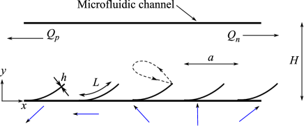
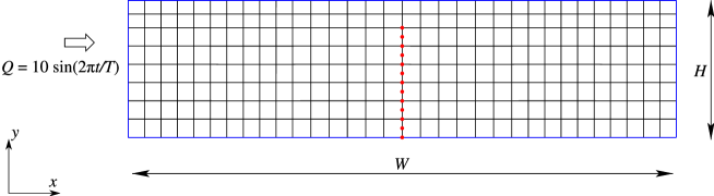
We study the flow in an infinitely long channel of height created by a two-dimensional array of plate-like magnetic artificial cilia (having length and thickness ), which are actuated using a rotating magnetic field which is uniform over each cilium, but with a phase difference between adjacent cilia. The external magnetic field experienced by the cilium is
| (1) |
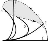
where is the magnitude of the applied magnetic field, the phase of the magnetic field , is the angular frequency and is the time period of rotation of the magnetic field. The magnetic field experienced by the individual cilia during a particular instance in time is shown using the blue arrows in Fig. 1(a). The phase difference in the applied magnetic field between adjacent cilia is . The chosen form of the phase makes the phase of the magnetic field at every cilium identical. That is, the magnetic field is periodic after repeats of cilia. Consequently, the applied magnetic field travels cilia units in time , so that the phase velocity of the magnetic field is (in cilia per second). The phase velocity is to the right (positive) and the magnetic field at each cilium position rotates counterclockwise with time. The typical asymmetric motion of a cilium is shown in Fig. 1(b). The cilia are tethered at one end to the surface, while the other end is free. The trajectory of the free end of a typical cilium is represented by the dashed lines in Fig. 1(b), with the arrows representing the direction of motion.
Due to the super-paramagnetic (SPM) nature of the cilia, for which the magnetization is proportional to the magnetic field, the magnetic body couple (, where is the magnetization of the cilia and is the magnetic field experienced by the cilia) depends only on the orientation and magnitude of the magnetic field, but not on its sign. As a result, the body couple at the cilium , which determines its motion, scales with Roper et al. (2006). This has consequences for the motion of the cilia, both temporally and spatially. Temporally, the frequency of the magnetic couple is twice that of the applied magnetic field. This results in two cilia beats for one 360∘ rotation of the magnetic field. Spatially, the phase of the magnetic couple is twice that of the applied magnetic field, so that the phase difference between neighbouring cilia is twice as large. This means that the magnetic couple is periodic after cilia. Since both the frequency and phase difference increase by a factor 2, the phase velocity of the magnetic torque remains equal to that of the magnetic field, i.e. . Note, however, that the phase velocity of the magnetic torque is equal to the velocity of the metachronal wave (i.e., the actually observed deformational wave travelling over the cilia) only when the phase difference is small (i.e. is large).
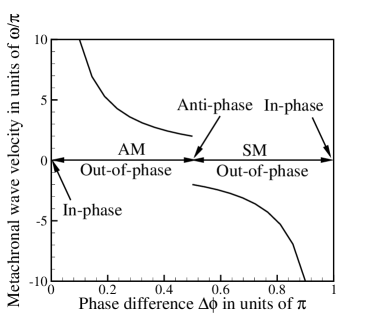
When the phase difference is too large, the metachronal wave can change sign, so that the metachronal wave is observed to travel in a direction opposite to the direction of the magnetic field (see appendix A). The metachronal wave velocity is equal to (i.e. to the right) when , and it is equal to (i.e. to the left) when , see Fig. 2. When , the magnetic couple is uniform and all cilia beat in-phase. When , the magnetic couple acting on two neighboring cilia is the same (because the phase difference of the magnetic couple is ), and again, all the cilia beat in-phase. When , the positive metachronal wave velocity is equal in magnitude to its negative counterpart. In such a condition, a standing wave is observed which causes the adjacent cilia to move in anti-phase. When the metachronal wave velocity is positive, i.e. to the right in Fig. 1. Consequently, the metachronal wave velocity is opposite to the direction of the effective stroke, which is commonly addressed as antiplectic metachrony (AM). When , the metachronal wave velocity is in the same direction as the effective stroke and is referred to as symplectic metachrony (SM), see Fig. 2.
2.1 Governing equations
We now briefly discuss the coupled solid-fluid magneto-mechanical numerical model used to study fluid propulsion using magnetically actuated plate-like artificial cilia. In typical microfluidic channels the height is smaller than the out-of-plane width. Moreover, the artificial cilia under study are plate-like (having an out-of-plane width much larger than their thickness and length ) exhibit a planar beat motion. Therefore, any variation in the out-of-plane direction can be neglected and under these assumptions it is sufficient to model the artificial cilia and the resulting flow in a two-dimensional setting.
2.1.1 Solid dynamic model
We model the cilia as elastic Euler-Bernoulli beams taking into consideration geometric non-linearity in an updated Lagrangian framework. As a starting point for the Euler-Bernoulli beam element formulation we use the principle of virtual work Malvern (1977) and equate the virtual work of the external forces at time () to the internal work (). The internal virtual work is given by
| (2) |
where and are the axial and transverse displacements of a point on the beam and is the density of the beam. Furthermore, is the axial stress and is the corresponding strain, given by
The external virtual work is
| (3) |
where and are the magnetic body forces in the axial and transverse directions, is the magnetic body couple in the out-of-plane direction, and are the surface tractions and is the out-of-plane thickness of the cilia.
We follow the approach used in Annabattula et al. (2010) to linearise and discretise the principal of virtual work to get,
| (4) |
where is the stiffness matrix that combines both material and geometric contributions, is the mass matrix that can be found in Cook et al. (2001), is the external force vector, is the internal force vector, is the nodal displacement increment vector and is the nodal acceleration vector. The nodal acceleration vector is discretized in time using Newmark’s algorithm (using parameters and ) so that Eqn. 4 can be written in terms of the velocity of the beam. The complete discretized equations of motion for the solid mechanics model can be found elsewhere (Khaderi et al., 2009).
2.1.2 Magnetostatics
To find the resulting magnetic forces, the magnetization of the cilia has to be calculated by solving the Maxwell’s equations in the deformed configuration at every time increment. The Maxwell’s equations for the magnetostatic problem with no external currents are
| (5) |
with the constitutive relation where is the magnetic flux density (or magnetic induction), is the magnetic field, is the magnetization, and is the permeability of vacuum. Equation 5 is solved for and using the boundary element method Khaderi et al. (2009). The magnetic couple per unit volume is given by . As the simulations are two dimensional, the only non-zero component of magnetic body couple is which is the source for the external virtual work in Eqn. 3. Since the applied magnetic field is uniform for each cilium, the magnetic body forces due to field gradients are absent.
2.1.3 Fluid dynamics and solid fluid coupling
We study the flow created by artificial cilia in the limit of low Reynolds number. The fluid is assumed to be Newtonian and incompressible. The physical behaviour of the fluid is governed by the Stokes equation:
| (6) |
where is the pressure in the fluid, is the rate of deformation tensor, is the velocity of the fluid and is the viscosity of the fluid. The set of equations in Eqn. 6 is solved using Eulerian finite elements based on the Galerkin method. The fluid domain is discretized into quadrilaterals in which the velocity and pressure of the fluid are interpolated quadratically and linearly, respectively. The velocity is calculated at the vertices, mid-sides and mid-point of the quadrilateral, and the pressure is calculated at the vertices. The solid and fluid domains are coupled by imposing the constraint that the velocity at the nodes of the solid beam are equal to the velocity of the surrounding fluid (point collocation method). This coupling is established with the help of Lagrange multipliers using the fictitious domain method. Details of the Eulerian finite element model and the coupling procedure can be found in van Loon et al. (2006).
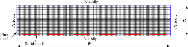
The fluid domain used for the simulations has a width and height (Fig. 3). For each value of , we choose to be a fraction larger than 2, with and integers, yielding a range of phase differences between 0 and . For each value of , a unit-cell of width needs to be chosen to account for periodicity in the magnetic couple, unless is an even integer, for which suffices. For example, let and . Now, and the phase difference is equal to . To maintain periodicity in the magnetic couple, the width of the unit-cell should be (containing 5 cilia). The top and bottom of the unit-cell are the channel walls, on which no-slip boundary conditions are applied,
while the left and right ends are periodic in velocity
2.1.4 Solution procedure
The solution procedure is as follows. The Maxwell’s equations are solved at every time instant to solve for the magnetic field. From the magnetic field, the magnetic body couple acting on the cilia is calculated and is provided as an external load to the coupled solid-fluid model, which simultaneously solves for the cilia velocity, and the velocity and pressure of the fluid. The velocity of the cilia is integrated using Newmark’s algorithm to obtain its new position, and the procedure is repeated. Each cilium is discretized into 40 elements and every fluid domain of size is discretized into elements, with the mesh being refined near each cilium. A typical mesh used for the simulations is shown in Fig. 3. A fixed time-step of 1 s was used for all the simulations reported in this paper. The spatial and temporal convergence of the numerical model is discussed in appendix C. The particles and streamlines are obtained from the velocity field in the fluid using the visualization software Tecplot Tecplot (2008). Also here care should be taken to accurately resolve the velocity field.
2.2 Parameter space
The physical dimensionless numbers that govern the behavior of the system are the magneto-elastic number - the ratio of the magnetic to the elastic forces, the fluid number - the ratio of viscous forces acting on the cilia to the elastic forces, and the inertia number - the ratio of the inertia forces of the cilium to its elastic forces, (see Khaderi et al., 2009). Here, is the elastic modulus of the cilia, is the thickness, is the density of the cilia, is the fluid viscosity, is the time period of one beat cycle and is the magnetic permeability. The geometric parameters that govern the behavior of the system are the phase difference , the cilia spacing , their length and the height of the channel . We study the flow created as a function of the cilia spacing (normalised with the length ) and the phase difference for the following set of parameters: , , and . The values of the physical parameters correspond to 100 microns, MPa, the thickness of cilia being m at the fixed end and 1 m at the free end, kg/m3, mPas, mT and the cycle time ms. The magnetic susceptibilities of the cilia are 4.6 along the length and 0.8 along the thickness van Rijsewijk (2006).
The fluid propelled is characterised by two parameters: the net volume of the fluid transported during a ciliary beat cycle and the effectiveness. The horizontal velocity field in the fluid at any position, integrated along the channel height gives the instantaneous flux through the channel. This flux integrated in time over the effective and recovery stroke gives the positive () and negative () flow, respectively (see Fig. 1). Due to the asymmetric motion, the positive flow is larger than the negative flow, generating a net area flow per cycle () in the direction of the effective stroke. The effectiveness, defined as , indicates which part of the totally displaced fluid is effectively converted into a net flow. An effectiveness of unity represents a unidirectional flow.
3 Results and discussion
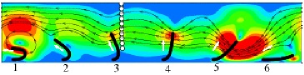
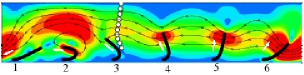
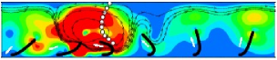
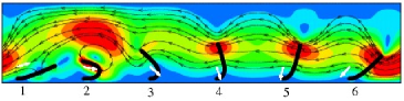
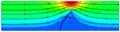
To obtain an understanding of fluid flow due to the out-of-phase motion of cilia, we analyse the case of antiplectic metachrony with a phase difference . Since is even, a unit-cell of width consisting of 6 cilia is chosen, see Fig. 4. The contours represent the absolute velocity normalised with . The direction of the velocity field can be determined from the arrows on the streamlines. The white arrows represent the applied magnetic field for each cilium. Animations of the ciliary motion for the cases of symplectic, antiplectic and anti-phase motion are provided as supplementary information.
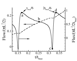
The snapshots shown in Figs. 4(a)-4(f) correspond to the time instances when the flux generated by the cilia is maximum. In Fig. 4 the instantaneous flux as a function of time (right axis) in addition to the flow (accumulated flux at time , left axis) are plotted. The time instances corresponding to Figs. 4(a)-4(f) are marked in Fig. 4. The motion of the fluid particles near the third cilium under the influence of the velocity field caused by the ciliary motion is also shown. It can be observed from Fig. 4 that one beat cycle consists of six sub-beats, which correspond to the traveling of the magnetic couple from one cilium to the next. The traveling of the metachronal wave to the right can, for instance, be seen by looking at the cilia which exhibit the recovery stroke (i.e. cilium 1 in Fig. 4(a), cilium 2 in Fig. 4(b), etc). The negative flow created by the cilia during their recovery stroke is overcome by the flow due to the effective stroke of the rest of the cilia; this leads to a vortex formation near the cilia exhibiting their recovery stroke. As a result, the negative flow is completely obstructed for most of the time during the recovery stroke. It can be observed from Fig. 4 that no flux (right axis) is transported in the negative direction, and that the flow (left axis) continuously increases during each sub-beat. Moreover, the increase in the flow during each sub-beat is similar (see Fig. 4). Thus, the total flow per beat cycle (left axis of Fig. 4) is the sum of the flows generated during each sub-beat (i.e. flow per beat = 6flow generated during one sub-beat). Therefore, it is sufficient to analyse the fluid flow during one sub-beat.
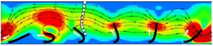

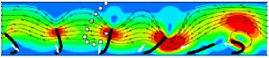
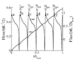

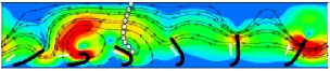
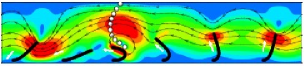
In the following, we analyse the fluid motion and the resulting flow during the second sub-beat. The velocity profiles at different instants of this sub-beat are shown in Figs. 5(a)-5(d). The corresponding flow and the flux generated are shown in Fig. 5. At , the third cilium starts its recovery stroke and the particles near the top boundary are driven by the positive flow created by cilia 4, 5 and 6 (see Fig. 5(a)). At this instant, as only one cilium is exhibiting a recovery stroke, the flux created by the cilia is maximum (see instant ‘a’ in Fig. 5). In Fig. 5(b), the third cilium also has begun its recovery stroke and now the negative flow caused by both the second and third cilia is opposed by the effective stroke of the other cilia. The high velocity of the second cilium during its recovery stroke decreases the flux caused by the other cilia (see instant ‘b’ in Fig. 5). When the third cilium is half-way through its recovery stroke (see Fig. 5(c)), the second cilium is about to finish its recovery, which generates a large velocity, due to the whip-like action Khaderi et al. (2009), to the right. Now, the position of the third cilium is such, that it opposes the negative flow caused by the second cilium. This leads to a strong vortex formation near the second and third cilia, with only a small flux in the direction of the recovery stroke (to the right). The small negative flux caused by the whip-like motion of the second cilium can be seen by the instant marked ‘c’ in Fig. 5, causing a momentary decrease in the flow. The vortex imparts a high velocity in the direction of the effective stroke to the particles away from the cilia. As the third cilium progresses further in its recovery stroke, the particles come under the influence of the flow due to the rest of cilia, which are now in different phases of their effective stroke (see Fig. 5(d)). Now, only the third cilium is in the recovery stroke; this again leads to a maximum value of the flux (similar to Fig. 5(a)). The key observation of Figs. 4 and 5 is that the negative flow created during the recovery stroke of the cilia creates a local vortex due to the positive flow created by other cilia. This shielding effect during the recovery stroke leads to a drastic increase in the net propulsion rate for cilia beating out-of-phase, compared to synchronously beating cilia.

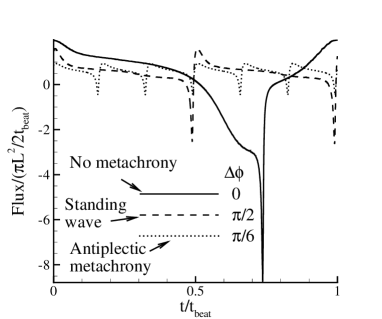
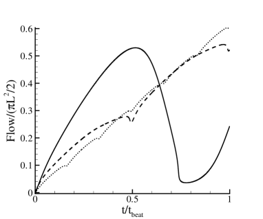
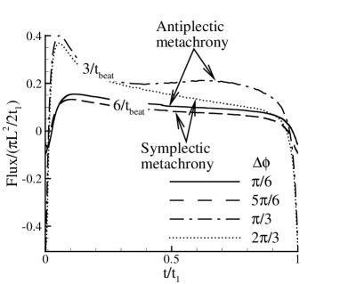
Next, we analyse the instantaneous flux (Fig. 6) and flow generated (Fig. 6) as a function of time for different phase differences. When the cilia move synchronously (), the flux (see the solid line in Fig. 6) is positive for approximately three-quarters of the time and strongly negative during the rest of the cycle. Consequently, the flow generated (see the solid line in Fig. 6) increases during the effective stroke, but profoundly decreases when the recovery stroke takes place. This creates a large fluctuation in the flow, with only a small net amount of fluid transported. Once the ciliary motion is metachronal, the negative flux is very small compared to the positive flow (see the cases of a standing wave and antiplectic metachrony in Fig. 6). This decreases the fluctuation in the flow generated, causing it to increase nearly monotonously during the beat cycle (see the dashed and dotted lines in Fig. 6). We can clearly see that the flow at the end of the beat cycle () for out-of-phase motion is significantly larger than the flow created by the synchronously beating cilia.
The fluid propelled and the corresponding effectiveness are plotted for different values of and in Fig. 7. The metachronal wave velocity (Fig. 2) is plotted as a function of and is shown using dashed lines in Fig. 7(a). As mentioned earlier, when the metachronal wave velocity is positive an antiplectic metachrony (AM) results, and when the metachronal wave velocity is negative we get a symplectic metachrony (SM). When all the cilia are moving synchronously ( or ), the flow (normalised by ) will be approximately 0.22 for . As the cilia density is increased by decreasing from to , the viscous resistance per cilium decreases, which causes the normalised flow to increase to 0.25. When the cilia beat in-phase, the effectiveness of fluid propulsion is very low, see Fig. 7(b).
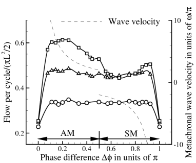
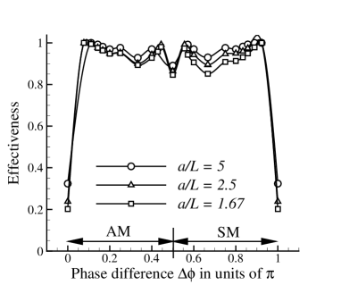
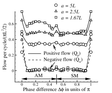
The fluid propelled shows a substantial increase once the cilia start beating out-of-phase (Fig. 7(a)). When the cilia spacing is large ( and ), the flow generated remains approximately constant for all metachronal wave speeds. The increase in flow by decreasing the cilia spacing from to is much larger when the cilia beat out-of-phase compared to the increase when the cilia beat in-phase. However, when the cilia spacing is low (), we see a larger increase in the fluid flow when there is an antiplectic metachrony(AM) compared to a symplectic metachrony (SM). Also, the effectiveness sharply increases from around 0.3 (i.e., 30% of the totally displaced fluid is converted into net flow) to 1 (fully unidirectional flow), see Fig. 7(b). To analyse these trends a bit further, we plot the positive and negative flow ( and in Fig. 1) created during a beat cycle for different phase differences in Fig. 8. It can be seen that the cilia do not create a negative flow when they beat out-of-phase for all cilia spacings, resulting in a unidirectional flow (effectiveness = 1). This reduction in negative flow is due to the shielding of flow during the recovery stroke caused by the effective flow of other cilia. It can also be noted that the positive flow is also reduced compared to in-phase beating, but the reduction is considerably less than the reduction in negative flow. Thus, the net flow increases as soon as the cilia start to beat out-of-phase (see Fig. 7(a)). It can be seen from Fig. 8 that in the presence of metachronal waves when the cilia spacing is large (), the fluid transported during the effective stroke remains nearly the same for all values of the wave velocities. For small cilia spacing (), however, the positive flow is maximal for antiplectic metachrony, which leads to a larger net flow for antiplectic metachrony compared to symplectic metachrony.
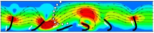
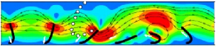
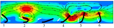
To understand the difference in positive flow for opposite wave directions for small inter-cilium spacing (), we plot the flux as a function of time scaled with the time taken by the magnetic couple to travel from one cilium to the next , for two different metachronal wave velocities ( and cilia per second), see Fig. 8. The corresponding phase differences are also shown in the legend. It can be seen that the flux in the case of antiplectic metachrony is larger than the flux created by the symplectic metachrony for the same wave speed. This difference in flux for opposite wave directions can be understood by analysing the velocity field corresponding to symplectic and antiplectic metachrony at time instances when the flux is maximum (see Fig. 9). Figure 9(a) and 9(b) correspond to different phase differences ( and , respectively) leading to a similar wave speed of cilia per second (see also Fig. 2). The fifth cilium is in the peak of its effective stroke for both AM and SM.
In the case of symplectic metachrony, the positive flow created by the fifth cilium is obstructed by the close proximity of the fourth cilium, which has just started its effective stroke. As a result, we observe the formation of a vortex. In the case of antiplectic metachrony, however, the position of the fourth cilium is such that the positive flow created by the fifth cilium is not obstructed. This leads to larger fluid flow in the positive direction, so that the net flow created by an antiplectic metachrony is larger than that created by its symplectic counterpart.
Reports on metachrony and phase locking of beating cilia have appeared in the past Gauger et al. (2009); Kim & Netz (2006); Gueron et al. (1997); Gueron & Levit-Gurevich (1999). The main results are that metachrony enhances flow compared to synchronously beating cilia Kim & Netz (2006); Gauger et al. (2009) and that antiplectic metachrony generates a higher flow rate than symplectic metachrony Gauger et al. (2009). Kim & Netz (2006) analysed two cilia, which are driven by internal motors and are moving out-of-phase due to the hydrodynamic interaction. They have shown that the fluid propulsion increases, once the cilia start to beat with a phase difference, which is in agreement with our results. Our results also agree with Gauger et al. (2009), where it is shown that the fluid flow is larger in the case of antiplectic metachrony than symplectic metachrony when the cilia are close together. However, our results differ from Gauger et al. (2009) in the sense that we always see an enhancement in flow in the presence of metachrony (compared to cilia beating in-phase) irrespective of the direction and magnitude of the metachronal wave velocity. This is most likely due to the fact that the asymmetry in ciliary motion in our case is much higher. Gueron et al. (1997) and Gueron & Levit-Gurevich (1999) have proposed that the evolution of the out-of-phase motion of cilia in Paramecia is due to hydrodynamic interactions between adjacent cilia leading to antiplectic metachrony. It is interesting to observe that the interplay between the internally-driven actuation and hydrodynamic interaction in nature results in antiplectic metachrony. Our results, and those of others Gauger et al. (2009), show that indeed antiplectic metachrony leads to larger flow than symplectic metachrony for small cilia spacings as typically seen in nature.
4 Conclusions
Using a numerical model we have studied the flow created by a two-dimensional array of plate-like artificial cilia as a function of the phase lag and spacing between neighbouring cilia. The flow per cycle and the effectiveness (which is a measure of the unidirectionality of flow) are considerably enhanced when the cilia start beating out-of-phase, as compared to synchronously beating cilia. While the amount of flow enhancement depends on the inter-cilia spacing, the effectiveness is not significantly influenced. Metachrony is observed to completely knock-down the negative flow to zero due to the vortex formation caused by the shielding of the recovery stroke. Interestingly, we find that the enhancement is achieved even for small phase differences. The direction of travel of the metachronal wave is important only for small cilia spacing. In that case, the flow is larger for antiplectic metachrony compared to symplectic metachrony, which is related to the obstruction of the positive flow for symplectic metachrony. It is therefore beneficial if the magnetic actuation of the artificial cilia is designed such that it results in an antiplectic metachrony. Our results suggest that an antiplectic metachrony is adopted by the cilia on paramecia and in the respiratory system to maximize the fluid propelled. However, ciliary systems (such as on Opalina) that exhibit symplectic metachrony are also present in nature. It will be of interest to investigate what property is optimised by symplectic metachrony in these systems.
Acknowledgements
This work is a part of the Framework European project ’Artic’, under contract STRP 033274. We would also like to acknowledge fruitful discussions with Michiel Baltussen and Patrick Anderson.
Appendix A Metachronal wave velocity
The metachronal wave velocity is obtained by dividing the distance between two cilia with the time it takes for the magnetic couple to travel from a cilium to its neighbor. If the neighbor is to the right, then the wave travels to the right, and when the neighbor is to the left, the wave travels to the left. The magnetic couple at any cilium is proportional to , and travels with a phase velocity of (in number of cilia per second) to the right.
In the schematic of Fig. 10, three cilia , and are depicted. At any given instance of time, let the magnitude of the magnetic couple at , and be , and , respectively. The magnitude of the magnetic couple at the ‘periodic’ cilium , which is separated from by units, is also . The metachronal wave is said to have traveled to the right when the magnetic field at is after a time interval. Now, the distance traveled by the magnetic couple is 1 cilia spacing, and the time taken to travel this distance is . Therefore, the velocity of the magnetic couple is , in cilia units per second. The metachronal wave is said to have traveled to the left when the magnetic field at is equal to after an interval of time. As the applied magnetic couple travels to the right, this situation is possible when the magnetic couple at the periodic cilium travels to the cilium . The time needed for the magnetic couple to travel from to is equal to . However, the apparent distance travelled is one cilium spacing to the left (i.e. from to ), so that the wave velocity is now . The (apparent) metachronal wave velocity is now determined by the maximum of the two competing wave velocities: to the right and to the left. As a result, the metachronal wave velocity is equal to (i.e. to the right) when (i.e. ), and it is equal to (i.e. to the left) when (i.e. ), see Fig. 2.

Appendix B Validation of the fluid-structure interaction model
To compare the performance of the present approach with a solution available in the literature we choose to study the deformation behavior of a cantilever beam under an imposed pulsating flow. This problem has been numerically solved by Baaijens (2001) using the fictitious domain method in which the solid was discretized using continuum finite elements. The width is four times the height of the fluid domain. is taken to be unity. The length of the cilium is . The thickness of the cilium is . The elastic modulus of the cilium and viscosity of the fluid were specified in dimensionless units to be and , respectively. The mesh used for the computation is shown in Fig. 11. The dots represent the nodes of the Euler-Bernoulli beam element. The boundary conditions are as follows: the left and right boundaries are periodic. A pulsating flow of magnitude is prescribed on the left boundary, where is the time period which is taken to be sufficiently large to avoid inertia effects in the cilium. The bottom boundary is a no slip boundary. On the top boundary, the normal flow is constrained. The solution from our formulation is plotted along with the solution from Baaijens (2001) in Fig. 12(a) in terms of the displacement of the free end of the cantilever. It can been seen that the two solutions are in good agreement. In Fig. 12(b), we plot the displacement of the free end of the beam as a function of time for different discretizations of the cilium (using 12, 24 and 48 beam elements). When the cilium mesh is refined, the fluid mesh is also refined proportionally, see also appendix C. It can be seen that the displacements nicely converge as the mesh is refined. The convergence of the velocity field is also shown in Fig. 13.


Appendix C Convergence of the numerical model
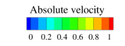
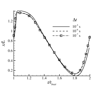
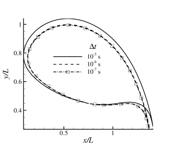
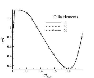
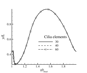
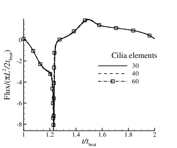
In this section, we report on the spatial and temporal convergence of the numerical method used in this paper. We use the case of synchronously beating cilia () with an inter-cilia spacing of , for which the unit-cell consists of one cilium. As the deformed shape of the cilium is an outcome of the model, we compare the position of the free end for different temporal discretizations. The mesh used to discretize the cilium and the fluid domain is shown in Fig. 14 for the case when the cilium is divided into 40 cilia elements and the fluid is divided into 28 30 elements.

The position of the tip of the cilium as a function of time and its trajectory for different time increments is shown in Fig. 15 (a)-(c). The time increment has to be small enough to capture the fast whip-like recovery stroke. It can be seen that a time increment of 1 s is sufficient for temporal convergence. This time step of 1 s is used to study the spatial convergence and the results are shown in Fig. 16. The number of elements on the cilium as well as the fluid are changed proportionally when the mesh is changed. In the following the spatial discretization is defined in terms of the number of elements used to discretise the cilium; i.e., 30 cilia elements correspond to a fluid mesh of 21 23 and 60 cilia elements correspond to a fluid mesh of 42 45. It can be seen that the results for these discretizations have fully converged as shown for the position of the free end of the cilium and the flux as a function of time.
References
- Annabattula et al. (2010) Annabattula, R. K., Huck, W. T. S. & Onck, P.R. 2010 Micron-scale channel formation by the release and bond-back of pre-stressed thin films: A finite element analysis. Journal of the Mechanics and Physics of Solids 58, 447–465.
- Baaijens (2001) Baaijens, Frank P. T. 2001 A fictitious domain/mortar element method for fluid-structure interaction. International Journal for Numerical Methods in Fluids 35 (7), 743–761.
- Belardi et al. (2010) Belardi, J., Schorr, N., Prucker, O., Wells, S., Patel, V. & Ruhe, J. 2010 Fabrication of articial rubber cilia by photolithography. In Second European Conference on Microfluidics - paper no. 112.
- Blake (1971a) Blake, J. R. 1971a Infinite models for ciliary propulsion. Journal of Fluid Mechanics 49 (02), 209–222.
- Blake (1971b) Blake, J. R. 1971b A spherical envelope approach to ciliary propulsion. Journal of Fluid Mechanics 46 (01), 199–208.
- Blake (1972) Blake, J. R. 1972 A model for the micro-structure in ciliated organisms. Journal of Fluid Mechanics 55 (01), 1–23.
- Blake & Sleigh (1974) Blake, J. R. & Sleigh, M. A. 1974 Mechanics of ciliary locomotion. Biological Reviews 49, 85–125.
- Brennen & Winet (1977) Brennen, Christopher & Winet, Howard 1977 Fluid mechanics of propulsion by cilia and flagella. Annual Review of Fluid Mechanics 9, 339–398.
- Chen et al. (2003) Chen, Lingxin, Ma, Jiping, Tan, Feng & Guan, Yafeng 2003 Generating high-pressure sub-microliter flow rate in packed microchannel by electroosmotic force: potential application in microfluidic systems. Sensors and Actuators B: Chemical 88, 260–265.
- Cook et al. (2001) Cook, Robert D., Malkus, D.S., Plesha, M.E., Malkus, David S. & Plesha, Michael E. 2001 Concepts and Applications of Finite Element Analysis. John Wiley and Sons.
- Dauptain et al. (2008) Dauptain, A., Favier, J. & Bottaro, A. 2008 Hydrodynamics of ciliary propulsion. Journal of Fluids and Structures 24 (8), 1156 – 1165, unsteady Separated Flows and their Control.
- Evans et al. (2007) Evans, B. A., Shields, A. R., Carroll, R. Lloyd, Washburn, S., Falvo, M. R. & Superfine, R. 2007 Magnetically actuated nanorod arrays as biomimetic cilia. Nano Letters 7 (5), 1428–1434.
- Fahrni et al. (2009) Fahrni, Francis, Prins, Menno W. J. & van IJzendoorn, Leo J. 2009 Micro-fluidic actuation using magnetic artificial cilia. Lab on a Chip 9, 3413 – 3421.
- Gauger et al. (2009) Gauger, E. M., Downton, M. T. & Stark, H. 2009 Fluid transport at low Reynolds number with magnetically actuated artificial cilia. The European Physical Journal E 28, 231–242.
- Gueron & Levit-Gurevich (1999) Gueron, S. & Levit-Gurevich, K. 1999 Energetic considerations of ciliary beating and the advantage of metachronal coordination. Proceedings of the National Academy of Sciences of the United States of America 96 (22), 12240–12245.
- Gueron et al. (1997) Gueron, S., Levit-Gurevich, K., Liron, N. & Blum, J. J. 1997 Cilia internal mechanism and metachronal coordination as the result of hydrodynamical coupling. Proceedings of the National Academy of Sciences of the United States of America 94 (12), 6001–6006.
- Jeon et al. (2000) Jeon, N.L., Dertinger, S.K.W., Chiu, D.T., Choi, I.S., Stroock, A.D. & Whitesides, G.M. 2000 Generation of solution and surface gradients using microfluidic systems. Langmuir 16 (22), 8311–8316.
- Khaderi et al. (2009) Khaderi, S. N., Baltussen, M. G. H. M., Anderson, P. D., Ioan, D., den Toonder, J. M. J. & Onck, P. R. 2009 Nature-inspired microfluidic propulsion using magnetic actuation. Physical Review E 79 (4), 046304.
- Khaderi et al. (2010) Khaderi, S. N., Baltussen, M. G. H. M., Anderson, P. D., den Toonder, J. M. J. & Onck, P. R. 2010 The breaking of symmetry in microfluidic propulsion driven by artificial cilia. Physical Review E 82, 027302.
- Kim & Netz (2006) Kim, Y. W. & Netz, R. R. 2006 Pumping fluids with periodically beating grafted elastic filaments. Physical Review Letters 96 (15), 158101.
- Kinosita & Murakami (1967) Kinosita, H. & Murakami, A. 1967 Control of ciliary motion. Physiological Reviews 47, 53–82.
- Laser & Santiago (2004) Laser, D J & Santiago, J G 2004 A review of micropumps. Journal of Micromechanics and Microengineering 14 (6), R35–R64.
- Liron (1978) Liron, N. 1978 Fluid transport by cilia between parallel plates. Journal of Fluid Mechanics 86 (04), 705–726.
- van Loon et al. (2006) van Loon, R., Anderson, P. D. & van de Vosse, F. N. 2006 A fluid-structure interaction method with solid-rigid contact for heart valve dynamics. Journal of Computational Physics 217, 806–823.
- Malvern (1977) Malvern, Lawrence E. 1977 Introduction to the Mechanics of a Continuous Medium. Prentice-Hall.
- Mitran (2007) Mitran, S. M. 2007 Metachronal wave formation in a model of pulmonary cilia. Computers and Structures 85, 763–774.
- Niedermayer et al. (2008) Niedermayer, Thomas, Eckhardt, Bruno & Lenz, Peter 2008 Synchronization, phase locking, and metachronal wave formation in ciliary chains. Chaos: An Interdisciplinary Journal of Nonlinear Science 18 (3), 037128.
- van Oosten et al. (2009) van Oosten, Casper L., Bastiaansen, Cees W. M. & Broer, Dirk J. 2009 Printed artificial cilia from liquid-crystal network actuators modularly driven by light. Nature Materials 8, 677 – 682.
- Qian et al. (2009) Qian, Bian, Jiang, Hongyuan, Gagnon, David A., Breuer, Kenneth S. & Powers, Thomas R. 2009 Minimal model for synchronization induced by hydrodynamic interactions. Phys. Rev. E 80 (6), 061919.
- van Rijsewijk (2006) van Rijsewijk, L. 2006 Electrostatic and magnetic microactuation of polymer structures for fluid transport. Master’s thesis, Eindhoven University of Technology.
- Roper et al. (2006) Roper, Marcus, Dreyfus, Rémi, Baudry, Jean, Fermigier, M., Bibette, J. & Stone, H. A. 2006 On the dynamics of magnetically driven elastic filaments. Journal of Fluid Mechanics 554 (-1), 167–190.
- Satir & Sleigh (1990) Satir, P & Sleigh, M A 1990 The physiology of cilia and mucociliary interactions. Annual Review of Physiology 52 (1), 137–155, pMID: 2184754.
- Schilling et al. (2002) Schilling, E.A., Kamholz, A.E. & Yager, P. 2002 Cell lysis and protein extraction in a microfluidic device with detection by a fluorogenic enzyme assay. Analytical Chemistry 74 (8), 1798–1804.
- Schorr et al. (2010) Schorr, N., Belardi, J., Prucker, O., Wells, S., Patel, V. & Ruhe, J. 2010 Magnetically actuated polymer flap arrays mimicking artificial cilia. In Second European Conference on Microfluidics - paper no. 105.
- Shields et al. (2010) Shields, A. R., Fiser, B. L., Evans, B. A., Falvo, M. R., Washburn, S. & Superfine, R. 2010 Biomimetic cilia arrays generate simultaneous pumping and mixing regimes. Proceedings of the National Academy of Sciences .
- Sing et al. (2010) Sing, Charles E., Schmid, Lothar, Schneider, Matthias F., Franke, Thomas & Alexander-Katz, Alfredo 2010 Controlled surface-induced flows from the motion of self-assembled colloidal walkers. Proceedings of the National Academy of Sciences 107 (2), 535–540.
- Smith et al. (2008) Smith, D.J., Gaffney, E.A. & Blake, J.R. 2008 Modelling mucociliary clearance. Respiratory Physiology and Neurobiology 163, 178–188.
- Smith et al. (2007) Smith, D. J., Gaffney, E. A. & Blake, J. R. 2007 Discrete cilia modelling with singularity distributions: Application to the embryonic node and the airway surface liquid. Bulletin of Mathematical Biology 69, 1477–1510.
- Tecplot (2008) Tecplot 2008 Tec360 user manual.
- den Toonder et al. (2008) den Toonder, Jaap, Bos, Femke, Broer, Dick, Filippini, Laura, Gillies, Murray, de Goede, Judith, Mol, Titie, Reijme, Mireille, Talen, Wim, Wilderbeek, Hans, Khatavkar, Vinayak & Anderson, Patrick 2008 Artificial cilia for active micro-fluidic mixing. Lab on a Chip 8 (4), 533–541.
- Vilfan & Jülicher (2006) Vilfan, Andrej & Jülicher, Frank 2006 Hydrodynamic flow patterns and synchronization of beating cilia. Phys. Rev. Lett. 96 (5), 058102.
- Vilfan et al. (2010) Vilfan, Mojca, Potocnik, Anton, Kavcic, Blaz, Osterman, Natan, Poberaj, Igor, Vilfan, Andrej & Babic, Dusan 2010 Self-assembled artificial cilia. Proceedings of the National Academy of Sciences 107, 1844–1847.
- West et al. (2002) West, Jonathan, Karamata, Boris, Lillis, Brian, Gleeson, James P., Alderman, John, Collins, John K., Lane, William, Mathewson, Alan & Berney, Helen 2002 Application of magnetohydrodynamic actuation to continuous flow chemistry. Lab Chip 2, 224–230.
- Zeng et al. (2002) Zeng, S., Chen, C., Santiago, J. G., Chen, J., Zare, R. N., Tripp, J. A., S., F. & Frechet, J. M. J. 2002 Electroosmotic flow pumps with polymer frits. Sensors and Actuators B: Chemical 82 (2-3), 209 – 212.