Mode III crack propagation in a bimaterial plane driven by a channel of small line defects
Abstract
We consider the quasi-static propagation of a Mode III crack along the interface in a bimaterial plane containing a finite array of small line defects (microcracks and rigid line inclusions). The microdefects are arranged to form a channel around the interface that can facilitate (or prevent) the crack propagation. The two dissimilar elastic materials are assumed to be weakly bonded, so that there is no kinking of the main crack from the straight path. On the basis of asymptotic formulae obtained by the authors, the propagation is analysed as a perturbation problem and the incremental crack advance is analytically derived at each position of the crack tip along the interface relative to the position of the defects. Numerical examples are provided showing potential applications of the proposed approach in the analysis of failure of composite materials. Extension to the case of infinite number of defects is discussed.
Keywords: Interfacial crack; Crack-microdefect interaction; Perturbation analysis; Dipole matrix.
1 Introduction
There is a vast literature devoted to the problem of the interaction between a stationary main crack and microdefects, in particular microcracks. The methods of solution range from complex potentials and the theory of analytic functions ([3, 4, 2]), singular integral equations ([13, 14, 15, 17, 16]), and the weight function and dipole matrix approach ([1, 8, 7]). However, the analysis of crack propagation, even in the quasi-static case, requires also the analysis of singular perturbations produced by a small advance of the crack tip across the microdefect field ([10, 12]).
The symmetric and skew-symmetric weight functions for a two-dimensional interfacial crack, recently derived by [10], can be efficiently employed to analyse the propagation of cracks along the interface in heterogeneous materials with small defects. In particular, the notion of skew-symmetric function is essential for the problem under consideration , since the “effective” loading produced by the defects on the crack faces is not symmetrical, in general.
We consider the quasi-static propagation of a Mode III crack along the interface in a bimaterial plane containing a finite array of small line defects. The microdefects are arranged to form a channel around the interface that can facilitate (or prevent) the crack propagation. The defect in question are microcracks and rigid line inclusion. The two elastic half-planes are assumed to be weakly bonded, so that there is no kinking of the main crack from the straight path. The defects are small compared to the distance from the crack tip and the distance between each other and, consequently, the interaction between them can be neglected. Using the superposition principle, each defect can be analysed separately and then the solution found by summing the contributions for all defects.
Fig. 1 shows a main crack at the interface between two dissimilar elastic material interacting with a small line defect at a finite distance from the crack tip. The shear moduli for the upper and lower half-planes are denoted by and , respectively. The line defect, which can be a microcrack or a movable rigid line inclusion, has length , where is a small dimensionless parameter, and its orientation with respect to the -axis is determined by the angle . The centre of the defect is denoted by , having polar coordinates and . The structure is loaded at the crack surfaces by two symmetrical point forces placed at a distance from the crack tip. The crack advance is denoted by .

The detailed asymptotic analysis for this problem can be found in [12], where the approach based on weight function and dipole matrix is used. In particular, the dipole fields for different types of defect are constructed and used together with symmetric and skew-symmetric weight functions for an interfacial crack ([10]) to derive the corresponding perturbation of the stress intensity factor acting at the main crack tip.
In the next section, we summarise the asymptotic formulae needed for the analysis of propagation of the crack in a finite channel of defects, which is presented in Section 3.
2 Asymptotic formulae
The propagation of the main crack is described as a perturbation problem, in which the stress intensity factor is expanded as follows
| (1) |
where is the stress intensity factor for the unperturbed crack, is the singular perturbation due to a small advance of the crack tip along the interface, and is the perturbation produced by a finite number of defects.
Following [12], the asymptotic formulae for the perturbation terms in (1) are given by
| (2) |
where is the coefficient in the second-order term asymptotics of the unperturbed solution, is the gradient of the unperturbed solution evaluated at , the centre of the defect, and is the dipole matrix associated with the type of defect:
– for a microcrack:
| (3) |
– for a movable rigid line inclusion :
| (4) |
The full-field solution for a Mode III crack in a bimaterial plane without defects can be found in [11, 7].
Assuming that the crack is propagating quasi-statically along the interface, the stress intensity factor remains constant and equal to the critical value, so that the perturbation term in parenthesis in (1) equals zero and we get the formula
| (5) |
which gives the incremental crack advance at each position of the crack tip, driven by the presence of the defects, . The procedure is iterated and the total crack elongation at arrest (corresponding to the first occurrence of the condition ) is computed as
| (6) |
where is the number of iterations.
3 Numerical computations
We consider the propagation of the main crack driven by a finite number of small line defects arranged to form a channel around the interface. Two different examples are discussed below, one consisting of only microcracks and the second consisting of microcracks and rigid line inclusions.
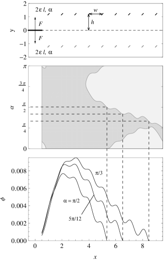
The first example is shown in Fig. 2a, upper part, consisting in 18 microcracks arranged in a 2 x 9 array. All the microcracks have the same length, , and distance from the interface, , measured from the centre of the microcracks. The parameter denotes the inclination of the microcracks in the first row, while microcracks in the second row have inclination , so that microcracks in the lower half-plane are perpendicular to the microcracks in the upper half-plane. The microcracks, above and below the interface, are separated one from the another by a constant distance, . The crack is loaded by a two-point symmetrical force applied at a distance from the crack tip. We analyse first the case of a weak interface in a homogeneous plane, that is the contrast parameter is set equal to zero.
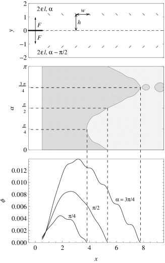
In the middle part of the figure we show the corresponding shielding-amplification diagram. We have shielding effect when the defects produce a decrease of the stress intensity factor, , or amplification effect in the opposite case, ([9, 5, 6]). On the horizontal axis we specify the position of the crack tip along the interface, measured from the point of application of the concentrated forces, while the vertical axis stands for the angle (). For three values of , namely , , , we report in the lower part of the figure the incremental crack advance as a function of the crack tip position . In the initial position, , the perturbation of the stress intensity factor is positive (amplification) and consequently the crack propagates, driven by the defects, and it stops when a neutral configuration is reached (line of separation between amplification and shielding regions). It appears that it is not possible to propagate the crack up to the end of the channel. Results show that the value is the most favourable for the crack propagation.
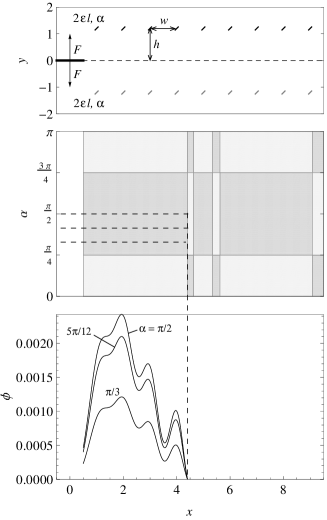
The geometric configuration for the second example is shown in Fig. 2b, upper part. It consists of a row of nine rigid line inclusions in the upper half-plane and a row of nine microcracks in the lower half-plane. All defects have the same length , inclination and distance from the interface and they are horizontally separated one from the another by the same distance . The main crack is loaded by a two-point force applied at a distance from the crack tip. In this case, the shielding-amplification diagram shows no dependence on the orientation of the defects, angle . Consequently, the total crack elongation before arrest is independent of and the crack stops approximately in the middle of the array, see the three propagation curves in the lower part of the figure.
The effect of the position of the two-point force with respect to the crack tip is illustrated in Fig. 3. Fig. 3a corresponds to the case shown in Fig. 2a but with two-point force applied at distance from the crack tip, instead of . Fig. 3b corresponds to the case shown in Fig. 2b but with two-point force applied at distance from the crack tip.

Two interesting observations can be made. First, we may note that the “speed” of the crack advance is much higher compared to the case when the force is applied close to the crack tip (the incremental crack advance is higher by two orders). This can be explained by noticing that, from the unperturbed solution reported in [7], we deduce
| (7) |
and consequently
| (8) |
Second, the crack propagates up to the centre of the channel, , in the first case, see Fig. 3a, while it propagates across and beyond the whole array in the second case, see Fig. 3b. Furthermore, the propagation curves in Fig. 3b show perfect symmetry with respect to the centre of the array.
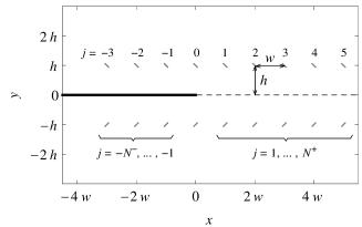
All these observations can be confirmed analytically by deriving the asymptotic approximation of as . In particular, we assume the configuration shown in Fig. 4. The crack tip is situated in correspondence of the line joining two defects on opposite sides of the interface. Moreover, we number the defects with index running from 1 to for the defects ahead of the crack tip, and from to for the defects behind the crack tip. The defects right above and below the crack tip are numbered .
For the case of Fig. 3a, microcracks above and below the interface, we use the formula valid for a single microcrack situated at the point (derived in [12])
| (9) |
By summation over all the defects and assuming that the materials are identical , we obtain as
| (10) |
It is noted that the contribution of the defects behind the crack tip, second sum in (10), equals, but with the opposite sign, the contribution of defects ahead of the crack tip, first sum. We deduce that the incremental crack advance becomes zero when the crack tip reaches the centre of the array, as confirmed by the numerical results in Fig. 3a.
For the case of Fig. 3b, rigid line inclusions above and microcrack below the interface, we use again the formula (9) and also the formula valid for a single rigid line inclusion situated at the point (derived in [12])
| (11) |
thus obtaining, for identical materials, as
| (12) |
In this case, the contribution of the defects behind the crack tip comes with the same sign as the contribution of the defects ahead of the crack tip, which explains the perfect symmetry about the centre of the array observed in Fig. 3b. Moreover, since is a common factor in (12), this formula also explains the constant thickness of the amplification region, , in Fig. 3b.
Furthermore, it is possible to extend the analysis to the case of an infinite number of defects ahead of the crack tip, , as the corresponding series in (10) and (12) are convergent. In the latter case, we obtain an explicit formula as
| (13) |
Finally, we would like to discuss the effects of inhomogeneity on the crack propagation. For a bimaterial plane and microcracks arranged as shown in Fig. 2a, results (not reported here) show that the shielding-amplification diagram and the propagation curves are very similar to the case of a homogeneous plane, reported in Fig. 2a. This result is expected, since the loading is symmetrical and the defects configuration is also symmetrical (apart from the inclination of defects, which is symmetrical only for the angle ).
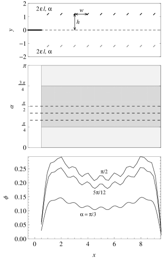
We consider now the case of rigid line inclusions above and microcracks below the interface, as shown in Fig. 2b, however now for a bimaterial plane with contrast parameter . In this case results, shown in Fig. 5, are completely different from the case of a homogeneous plane, compare with Fig. 2b. Now the shielding-amplification diagram shows dependence on the angle of orientation of the defects with respect to the -axis. Consequently, the total crack elongation at arrest is different for different ’s, as shown by the three propagation curves in the lower part of the figure. Also, if we swap the two materials, such that , results (not reported here) show that the crack cannot propagate, since a shielding effect takes place instead of amplification effect at the initial position of the crack tip.
4 Conclusions
The problem of propagation of a main interfacial crack in a bimaterial plane containing a finite channel of small line defects and subject to antiplane loading conditions is analysed on the basis of asymptotic formulae derived by the authors. Under the assumption of quasi-static propagation, the shielding-amplification effect of the microdefects on the main crack tip is obtained at each position of the crack tip and the incremental crack advance is derived asymptotically.
Two numerical examples are shown for two different microdefect arrangements. Results show that the channel of microdefects can facilitate (amplification) or prevent (shielding) the propagation of the main crack. In particular, the orientation of the microdefect can be tuned such that the main crack stops at a given position along the channel. We discuss the possibility to extend the asymptotic formulation to the case of a channel with infinite number of small defects.
Acknowledgements. This research was supported by the Research-In-Groups (RiGs) programme of the International Centre for Mathematical Sciences, Edinburgh, Scotland. In addition, A.P. and G.M. gratefully acknowledge the support from the European Union Seventh Framework Programme under contract numbers PIEF-GA-2009-252857 and PIAP-GA-2009-251475, respectively.
References
- [1] D. Bigoni, S. Serkov, A. Movchan, and M. Valentini. Asymptotic models of dilute composites with imperfectly bonded inclusions. Int. J. Solids Struct., 35:3239–3258, 1998.
- [2] S. X. Gong. On the main crack–microcrack interaction under mode iii loading. Eng. Fract. Mech., 51:753–762, 1995.
- [3] S. X. Gong and H. Horii. General solution to the problem of microcracks near the tip of a main crack. J. Mech. Phys. Solids, 37:27–46, 1989.
- [4] S. X. Gong and S. A. Meguid. Microdefect interacting with a main crack: A general treatment. Int. J. Mech. Sci., 34:933–945, 1992.
- [5] J. W. Hutchinson. Crack tip shielding by micro-cracking in brittle solids. Acta Metall., 34:1605–1619, 1987.
- [6] S. Loehnert and T. Belytschko. Crack shielding and amplification due to multiple microcracks interacting with a macrocrack. Int. J. Fract., 145:1–8, 2007.
- [7] G. Mishuris, A. B. Movchan, N. Movchan, and A. Piccolroaz. Interaction of an interfacial crack with linear small defects under out-of-plane shear loading. Comp. Mater. Sci., page doi:10.1016/j.commatsci.2011.01.023, 2011.
- [8] A. B. Movchan, N. V. Movchan, and C. G. Poulton. Asymptotic Models of Fields in Dilute and Denselly Packed Composites. Imperial College Press, London, 2002.
- [9] M. Ortiz. Continuum theory of crack shielding in ceramics. J. Appl. Mech., 54:54–58, 1987.
- [10] A. Piccolroaz, G. Mishuris, and A. B. Movchan. Symmetric and skew-symmetric weight functions in 2d perturbation models for semi-infinite interfacial cracks. J. Mech. Phys. Solids, 57:1657–1682, 2009.
- [11] A. Piccolroaz, G. Mishuris, and A. B. Movchan. Perturbation of mode iii interfacial cracks. Int. J. Fract., 166:41–51, 2010.
- [12] A. Piccolroaz, G. Mishuris, A. B. Movchan, and N. Movchan. Perturbation analysis of mode iii interfacial cracks advancing in a dilute heterogeneous material. Int. J. Solids Struct., page doi:10.1016/j.ijsolstr.2011.10.006, 2011.
- [13] N. Romalis and V. Tamuzh. Propagation of a main crack in a body with distributed microcracks. Mech. Composite Mater., 20:35–43, 1984.
- [14] A. A. Rubinstein. Macrocrack-microdefect interaction. J. Appl. Mech., 53:505–510, 1986.
- [15] A. A. Rubinstein and H. Choi. Macrocrack interaction with transverse array of microcracks. Int. J. Fract., 36:15–26, 1988.
- [16] V. Tamuzs, V. Petrova, and N. Romalis. Plane problem of macro-microcrack interaction taking account of crack closure. Eng. Fract. Mech., 55:957–967, 1994.
- [17] V. Tamuzs, N. Romalis, and V. Petrova. Influence of microcracks on thermal fracture of macrocrack. Theor. Appl. Fract. Mech., 19:207–225, 1993.