Bistable defect structures in blue phase devices
Abstract
Blue phases (BPs) are liquid crystals made up by networks of defects, or disclination lines. While existing phase diagrams show a striking variety of competing metastable topologies for these networks, very little is known as to how to kinetically reach a target structure, or how to switch from one to the other, which is of paramount importance for devices. We theoretically identify two confined blue phase I systems in which by applying an appropriate series of electric field it is possible to select one of two bistable defect patterns. Our results may be used to realise new generation and fast switching energy-saving bistable devices in ultrathin surface treated BPI wafers.
pacs:
61.30.Jf,42.79.Kr,61.30.DkLiquid crystals are materials with spontaneously broken symmetry: as such they support topological defects of various kinds and may be used as testing grounds for theories on many areas of physics, e.g. the dynamics of cosmic strings and of vortex lines in superfluids and superconductors Other . Blue phases (BPs) are a spectacular example of soft matter in which a network of such defects self assembles as a fully periodic cubic three-dimensional structure whose local director has a double-twist configuration mermin . The defects are arranged in a regular fashion, with periodicity at length scales comparable with the wavelenght of light. This is the reason why BPs exhibit selective Bragg reflection in the range of visible light and can have interesting applications in fast light modulators dim89 and tunable photonic crystals photonic . BPs were initially observed to be stable only in a narrow range of temperature , but recently new compounds, stable in wider interval over (including room temperature), have been developed kiku ; coles . These studies can be considered with good reason as seeds for the recent fabrication of the first blue phase display device with fast switching times sams . On the other hand BPs have attracted broader interest among physicists because double-twist cylinders represent a striking example of the so-called skyrmions, topological excitations encountered in nuclear physics nucl_brown , in spinor Bose-Einstein condensates usama , and in ferromagnetic materials, where they have been observed science .
Theory and experiments have mapped out a number of phase diagrams reporting a remarkably varied range of competing metastable disclination networks mermin ; dupuis . However, there are only very few theoretical studies to date regarding the dynamics of the formation of BPs, and virtually none addresses how to switch from one state to another reversibly in a controlled way. Here we provide the first theoretical study to achieve this goal, and give two specific examples of a bistable BPI system, where an electric field along the appropriate direction can select one of two metastable arrangement of defects. Besides being of interest per se, as an intriguing example of controlled defect dynamics, our discovery suggests specific novel geometries which may be used to realise bistable BP based devices. Devices like the ones we have found are important technologically as each of the bistable states is metastable and is retained after the field is switched off: this fact eliminates the need of having a constant electric field to keep the system in the “on”state, hence sharply reducing energy consumptions. Some examples of such systems are the zenithal bistable device (ZBD) zenit and surface-stabilised cholesteric texture (SSCT) devices kent . In the ZBD case bistability relies on flexoelectricity and requires a periodic grating of the surfaces, whereas in the SSTC case it exploits the existence of focal conic defects, which compete against the defect-free helical texture when strong anchoring is used. Several other nematic multistable devices also exist (see e.g. nem_dev ). Our case is different as the switching occurs between two disclination networks. BP devices such as the one we suggest should also share the faster switching times made possible by BP cells. At the same time, simulations are key to clarify the dynamics of the defect reorganisation underpinning bistability zenit ; nem_dev .
In this work we propose two novel BPI (blue phase with symmetry) geometries, for which it is possible to design a simple switching on-off schedule that leads to a bistable defect network. In both cases, bistability is present for a sizeable range of parameters (quantified below) and is characterized by the presence of two states, which are both metastable when the field is off and have a fully 3D defect structure. The first device we propose relies on surface memory effects which retain the BPI structure on the boundaries, and the two competing states are the standard bulk BPI network and another arrangement, which is only slightly higher in free energy. The second device exploits the additional frustration driven by strong homeotropic anchoring in a confined thin sample, which conflicts with the bulk ordering. We find that this leads to the appearance of multiple defect states, similar to the ones observed in fukuda2 (a), which, importantly, can be uniquely selected by the application of an electric field along an appropriate direction. Our devices are entirely different from the BP bistable device described in wang . Firstly, in that device the dielectric anisotropy is negative, while in our case it is positive. Secondly, the switching in wang is between two field-induced metastable states, which are selected by different values of an applied voltage, whereas in our case the electric fields is switched on and off along different directions.
The physics of a BP device may be described by a Landau-de Gennes free energy written in terms of the tensor order parameter mermin . This comprises a bulk term , and a distortion term mermin , where is the elastic constant and the pitch of the cholesteric liquid crystal is given by . is a constant, controls the magnitude of the ordering and is the Levi-Civita antisymmetric third-rank tensor. The constants , and are chosen in order to be in the appropriate region of the phase diagram dupuis . We have set , , for which BPI is stable. This choice may be mapped to a rotational viscosity equal to 1 Poise, (Frank) elastic constants equal to pN and a blue phase periodicity equal to 300 nm. Moreover one space and time unit correspond to 0.0125 m and 0.0013 s. The contribution of the boundaries is encoded in a surface free-energy term, given by , where (larger than in our simulations) controls the anchoring strength and is the order parameter at the surfaces. The interaction with an external electric field is accounted for by an additional term, , where (here taken 0) is the dielectric anisotropy of the material. The electric field may be quantified via the dimensionless number . By assuming a dielectric anisotropy of rao , one finds that an electric field of corresponds to . The simulation domains along the three coordinate axes are , and respectively, with periodic boundaries along and . All our results are performed on lattices of dimensions . The equation of motion for Q is , where is a collective rotational diffusion constant and is the material derivative for rod-like molecules beris . The molecular field is the thermodynamic force that drives the system towards the equilibrium beris . The velocity field obeys a Navier-Stokes equation with a stress tensor generalised to describe LC hydrodynamics beris . The interplay between the velocity field and the order parameter is referred to as backflow. To solve the equations of motion, we used a hybrid lattice Boltzmann algorithm, as in nem_dev .
The usual zero-field defect structure in the BPI cell is shown in Fig. 1a. We first focus on the case in which the director field is fixed at the top (, being the sample size) and bottom () boundaries of the cubic cell to its stable structure in absence of a field. This may be achieved by pinning due to impurities or through surface memory effects helfr2 .
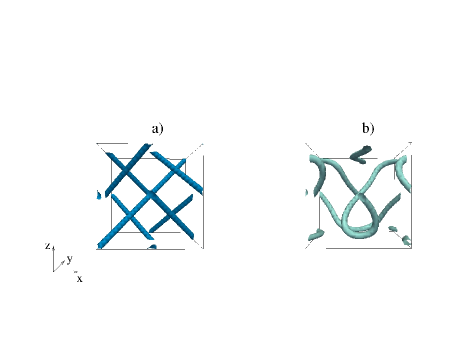
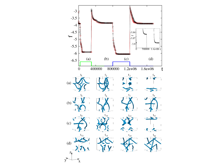
Fig. 2a-d shows the evolution of the defect network in response to an electric field switched on and off first along , then along . During the cycle the defect dynamics is highly non-trivial and is characterized by a complex reorganization driven by the electric field, and depending on its direction. In particular, after the application of the field along , the defects twist and bend and eventually recombine, annihilating in the bulk and forming defect arcs pinned at the walls (). The voltage () is chosen strong enough to break the defect structure in the bulk. When the field is switched off, some disclinations migrate back to the centre of the cell, giving rise to connected boundary arcs that span the entire device (). The system gets stuck into a stationary metastable state (), whose free energy is different from the one of the zero-field state (see inset of Fig. 2, top panel). Due to the anisotropy of the BPs, it is now interesting to ask what is the defect dynamics if the electric field acts on a different direction. Starting from the configuration at time we have switched on an electric field along the direction, with voltage equal to the one chosen for the field in direction. The defects now start to deform, bending in the direction of the field (), and then move towards the bulk where they met and form unstable branching points that annihilate. This second field-induced state () is again (as the one at time ) characterized by boundary arcs. By switching off the field, the system reorganizes as the boundaries force the disclinations towards the bulk: surprisingly, the dynamics now leads back to the starting bulk BPI (Fig. 1a). Bistability is affected by the voltages used in the switching. We have simulated the same device for and found that it is bistabile in both cases. On the other hand, bistability is lost for and the switching dynamics is now characterized by a reversible cycle in which a zero-field state (different from the bulk BPI structure, Fig 1a), obtained after the application of the electric field along , is recovered even after switching along . Note also that the results in Fig. 2 refer to BP devices with : intriguingly, in the case of negative dielectric constant the device can never get back to the bulk BPI state. This may be due to the fact that in the presence of a field the director can form a helix along the field, and this is not different enough in free energy from the BP state to drive a reorganisation of the unit cell once the field is removed. To check the robustness of our results, we have also simulated the device with different values of and (e.g. and ), again leading to a stable BPI – even in this different region of phase space we find that the device is bistable. Finally, in Fig. 2, top panel, we also compare the free energies as a function of time both in the presence and absence of hydrodynamics. The effect of backflow is to slightly speed up all relaxations, without deep consequences on the dynamic evolution.
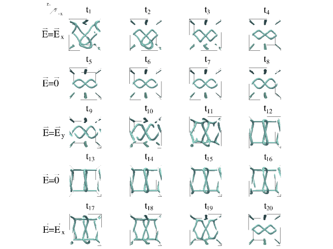
We now turn to the case of different boundary conditions. Fixed boundary conditions (FBCs), as the ones we have just employed, have often been used in cholesterics and BPs helfr2 . However in practice it is more feasible to control the alignment of the director field at the boundaries by chemical treatment or rubbing. The former technique typically is used to enforce homeotropic (or perpendicular) anchoring of the director at the wall, the latter yields homogeneous (or parallel) anchoring. Therefore it is interesting to know how these boundaries affect the switching dynamics of a BP device, and, importantly, whether they can still lead to a bistable behaviour. In what follows we focus on a BPI device with homeotropic anchoring at both walls. To the best of our knowledge there is only one study about the equilibrium disclination configuration in confined BPI cell with homeotropic anchoring fukuda2 (a) while nothing is known about electric field effects in these thin cells. As we shall see, by using the same electric field dynamical schedule adopted for the cell with FBCs, it is still possible to realise a switchable bistable device, albeit with some key conceptual differences with respect to the device in Fig. 1a. The first one is that homeotropic anchoring affects the zero-field equilibrium defect structure (Fig. 1 b)), now characterized by bent disclinations depinned from the walls – the original topology of BPI being preserved. The second important difference is that the change of the boundary conditions affects the dynamic evolution under an electric field: the minimum value required to destabilise the initial topology is now . This decrease in the threshold is because the wall now pins the zero-field structure more weakly than in the case of Fig. 1. In spite of these differences, there is a range in which the device shows bistability, and the switching dynamics of the defect network is reported in Fig. 3. When the electric field is switched on along the direction (), the defects start to deform, bend and form a spectacular double-helix pattern in the bulk, accompanied by columnar defects at the wall. This structure is induced and stabilised by the electric field, yet it only suffers minor rearrangements as the field is switched off. This double-helical state has already been observed in Ref. fukuda2 (a) in the absence of a field – it could be selected for instance by tuning the device thickness. When we switch on the field again, now along the direction (see snapshots ), the bent double-helix moves towards the walls () where it joins up with the the columnar disclinations, to form a transient interconnected structure () which later on relaxes to an array of twisted ring defects in the bulk, accompanied again by straigth disclinations, this time at right angles with the one associated with the double helical state (). Once more the field-induced rings do not change much upon switching off (). We note that a state similar to these ring defects has recently been observed in Ref. fukuda2 (b), however in a system with homogeneous anchoring at the walls. Our simulations therefore show that the number of possible defect networks in these thin BP cells are even more than previously thought. In order to behave as a switchable bistable device, our system still needs to be able to reconstruct the double-helical state starting from the ring defect structure. This is indeed what happens if the field is switched on and off along the direction (as in the first cycle). The ring defects initially enlarge and touch the walls where disclination lines reform (). Thereafter the double-helix pattern reconstructs in the bulk () and later on stabilises. Thus our thin BP sample with homeotropic anchoring behaves as a bistable device, and the two switchable states are the double helical and twisted ring structures – unlike the surface memory device none of these equals the zero-field stable state.
In summary, we have investigated the hydrodynamics of a cubic BPI cell and proposed two systems, differing in the boundary conditions, which can switch between two bistable disclination structures under the action of an applied field. In the first one we have fixed boundary conditions at both walls, while in the second one we considered homeotropic anchoring. In the FBCs cell, the two switchable states are the zero-field BPI and another metastable defect network. The device with homeotropic anchoring, on the other hand, switches between two states which are metastable in the absence of a field. In one of these states the defects form a double helix, whereas in the other one they arrange as an array of twisted rings – these configurations are alternatively observed by varying the direction and the magnitude of the electric field. The bistable behaviour of this device is promising for technological applications to energy-saving devices because, in principle, the required anchoring could easily be achieved. The physical reason behind the viability of BP bistable devices may be the glassy free energy profile which admits a number of competing metastable minima, each of which is potentially suited for their design, provided a suitable kinetic route to achieve reversible switching is discovered. In this respect, one may expect that even more BP bistable systems may be found in the future.
References
- (1) M. B. Hindmarsh and T. W. B. Kibble, Rep. Prog. Phys. 58, 477 (1995); A. Bulgac et al., Science 332, 1288 (2011); R. A. Borzi et al., Science 315, 5809 (2007).
- (2) D. C. Wright, N. D. Mermin, Rev. Mod. Phys. 61, 385 (1989) and references therein.
- (3) V.E. Dmitrenko, Liq. Cryst. 5, 847-851 (1989).
- (4) P. Etchegoin, Phys. Rev. E 62, 1435-1437 (2000).
- (5) H. Kikuchi et al.,Nat. Mater. 1 64 (2002).
- (6) H. J. Coles and M. N. Pivnenko, Nature 436, 997 (2005).
- (7) www.physorg.com/news129997960.html (2008)
- (8) G. E. Brown and M. Rho, Phys. Rep. 363, 85 (2002).
- (9) U. Al Khawaja and H. Stoof, Nature 411, 918 (2001).
- (10) S. Mühlbauer et al., Science, 323, 915 (2009).
- (11) A. Dupuis, D. Marenduzzo, J. M. Yeomans, Phys. Rev. E 71, 011703 (2005).
- (12) C. Denniston and J. M. Yeomans, Phys. Rev. Lett. 87, 275505 (2001); L.A. Parry-Jones and S. J. Elston, J. Appl. Phys., 97, 093315 (2005).
- (13) D. K. Yang et al., Ann. Rev. Mat. Sci. 27, 117 (1996); D. K. Yang et al., J. Appl. Phys. 76, 1331 (1994).
- (14) R. Barberi, M. Giocondo and G. Durand, Appl. Phys. Lett. 60, 1085 (1992); J. Kim, M. Yoneya, H. Yokoyama, Nature 420, 159 (2002); A. Tiribocchi et al., Appl. Phys. Lett. 97, 143505 (2010).
- (15) J. Fukuda, S. Zumer, Phys. Rev. Lett. 104, 017801 (2010); Phys. Rev. Lett. 106, 097801 (2011).
- (16) C.-T. Wang et al., Appl. Phys. Lett. 96, 041106 (2010).
- (17) L. Rao et al., Appl. Phys. Lett. 98, 081109 (2011).
- (18) A. N. Beris and B, J. Edwards, Thermodynamics of Flowing Systems, Oxford University Press, Oxford (1994).
- (19) T. C. Lubenski, Phys. Rev. A 6, 452 (1972); A. Tiribocchi et al., Soft Matter 7, 3295 (2011).