DECam integration tests on telescope simulator
Abstract
The Dark Energy Survey (DES) is a next generation optical survey aimed at measuring the expansion history of the universe using four probes: weak gravitational lensing, galaxy cluster counts, baryon acoustic oscillations, and Type Ia supernovae. To perform the survey, the DES Collaboration is building the Dark Energy Camera (DECam), a 3 square degree, 570 Megapixel CCD camera which will be mounted at the Blanco 4-meter telescope at the Cerro Tololo Inter-American Observatory. DES will survey 5000 square degrees of the southern galactic cap in 5 filters (g, r, i, z, Y). DECam will be comprised of 74 250 micron thick fully depleted CCDs: 62 2k x 4k CCDs for imaging and 12 2k x 2k CCDs for guiding and focus. Construction of DECam is nearing completion. In order to verify that the camera meets technical specifications for DES and to reduce the time required to commission the instrument, we have constructed a full sized telescope simulator and performed full system testing and integration prior to shipping. To complete this comprehensive test phase we have simulated a DES observing run in which we have collected 4 nights worth of data. We report on the results of these unique tests performed for the DECam and its impact on the experiment s progress.
keywords:
Dark Energy , CCD , camera , survey1 Introduction
The Dark Energy Survey (DES, darkenergysurvey.org) [1, 2, 3] is a ground-based photometric survey conceived to shed light on the problem of the accelerated expansion of the universe by measuring the dark energy equation of state parameter with four complementary techniques: galaxy cluster counts, weak lensing, galaxy angular power spectrum and Type Ia supernovae. The combination of these techniques will result in a factor of 3-5 improvement over current experiments in the figure of merit defined by the Dark Energy Task Force [4]. This will be achieved by measuring, in the redshift range , redshifts and shapes of 300 million galaxies, mass and redshifts of tens of thousands of galaxy clusters, luminosity and redshifts of about 4000 Type Ia supernovae. DES will survey a 5000 square-degrees area of the sky in the optical grizY bands and its total volume, estimated to be of 24 Gpc3, is 7 times larger than the largest existing CCD survey of the Universe by volume to date, the Sloan Digital Sky Survey Luminous Red Galaxies photometric sample [5]. DES will also provide the astronomical community with a wide field, 5 band digital survey of the southern sky with excellent image quality, uniform photometry and unprecedented depth for its sky coverage.
To accomplish our science goals the DES collaboration has designed [6, 7] and built [8, 9] the Dark Energy Camera (DECam) [10, 11], a new imaging instrument comprised with 74 250 micron thick CCDs [12, 13]. DECam will be installed on the Cerro Tololo Inter-American Observatory (CTIO) 4-meter Blanco telescope [14]. DES will use 525 nights of DECam observations carried in the 2012-2017 austral spring and summer months.
Construction of DECam is nearing completion. In order to verify that the camera meets technical specifications for DES and to reduce the time required to commission the instrument, we have constructed a full sized telescope simulator [15] and performed full system testing and integration prior to shipping. In this paper we report on the results of these unique tests performed for the DECam and its impact on the experiment’s progress. Updated overviews of the DECam project [16], the CCD properties [17] and readout electronics [18] can be found in this conference proceedings volume.
This paper is organized as follows: Section §2 describes the DECam hardware components available for testing on the telescope simulator (§2.1) and the data acquisition system (§2.2). Section §3 details the telescope simulator setup, goals and methods. Section §4 presents the data taken during this test phase. Our results are discussed in section §5 and followed by a brief Conclusions section, §6.
2 Instrument
2.1 DECam
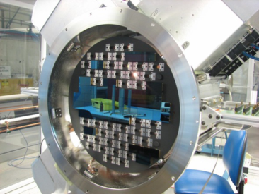
DECam is a new imaging instrument for the Blanco 4-meter telescope at CTIO. Its major components are: a 570 Megapixel cryocooled [19] optical CCD imager with 74 250 microns thick detectors [13] that were developed at LBNL [12] and packaged at Fermilab [20, 21, 22, 23, 17], a low noise readout system [24, 25, 18] housed in actively cooled crates, a two-blade shutter, a filter changer with 8 slots (5 of which used for DES filters), a hexapod for real-time focus and alignment with precision of 1-micron and an optical corrector with 5 lenses [26]. Of the 74 CCDs, 62 are 4k x 2k chips used for science imaging, 12 are 2k x 2k of which 4 are used for guiding and 8 for focus. Figure 1 shows these main components, highlighting those that were available for testing at the telescope simulator: (a) the readout crates, (b) the imager focal plane, (c) shutter and filter changer, (d) hexapod. Also shown in the picture are the corrector lenses and the barrel. The focal plane was loaded with 27 engineering grade CCDs (24 imaging, 3 guiding detectors) as shown in Fig. 1.
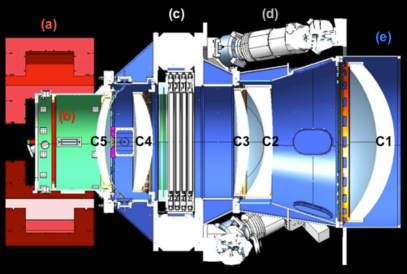
Tests with the final set of 74 science grade CCDs currently installed on the focal plane were performed after we were satisfied with the results on the telescope simulator. We did not include any of the optics components in our tests. Both lenses and filters were tested independently and are being shipped directly to CTIO. We used dummy weights in the place of the optical components and a flat optical window instead of C5 for our tests.
2.2 Data acquisition system
Survey Image System Process Integration (SISPI) is the DES data acquisition system [27]. Image data from the focal plane CCDs, read by the Monsoon front end electronics, flow to the Image Acquisition and Image Builder systems before being recorded on a storage device and handed over to the DES Data Management system [28]. The data flow is coordinated by the Observation Control system (OCS) which determines the exposure sequence and is assisted by the Instrument Control (ICS) and Image Stabilization systems. Pointing information, correction signals derived from the guide CCDs and other telemetry information is exchanged with the Blanco Telescope Control system (TCS). The ICS implements hardware control loops for the shutter, filter changer and cooling system. With 62 CCDs or 520 Mega pixels and 16 bits per pixel, one DECam exposure generates approximately 1 GByte of data. At a rate of 250 kpix/s it takes about 17 seconds to transfer the data from the focal plane to the computers of the Image Acquisition system. During this time the telescope slews to the next position and SISPI must be ready for the next exposure. The images transfer via Gigabit Ethernet links to the Image Building system where it is packaged in multi-extension FITS files and stored on disk. The SISPI applications are built upon a common software infrastructure layer which provides the message passing system, the facility database and support for configuration and initialization. In SISPI we distinguish between Command messages and Telemetry data. Commands are used to request information from a remote application or to activate a remote action. The Command or Message Passing system is implemented using a Client-Server design pattern based the CTIO developed Soar Messaging Library (SML). Telemetry in this context refers to any information an application provides and that can be of use to another application. In order to provide this functionality we implemented a Shared Variable system (SVE) using the Publish-Subscribe design pattern. The read-out and control system are operational and were tested on the telescope simulator.
3 Telescope Simulator: concept, goals and methods
The Telescope Simulator [15], shown in Fig. 2 is a full-size replica of the Blanco telescope top end rings and the fins that connect the camera to those rings.
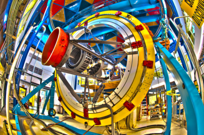
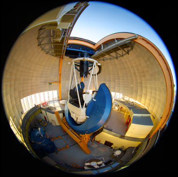
The camera, fins, and rings are supported by a frame that provides pitch and roll capability to orient that equipment as if it were at the top of a telescope. Though the machine has the capability to move, it does not mimic the slewing or guiding capability of the telescope, which means that our tests were performed with DECam statically positioned at different orientations. The telescope simulator is 14 ft tall and 25 ft wide. The four rings weigh 32,000 pounds. The outer one has a 24 ft diameter. Two motors from SEW Eurodrive can orient the camera to any angle within the pitch and roll degrees of freedom. The pitch motor is 1/3 HP, 1800 RPM, directly-coupled, torque-limited and geared down 35,009:1 for a maximum speed of 20 minutes per revolution. The roll motor is 1/2 HP, 1800 RPM, geared down 709:1 for a maximum speed of 11.5 minutes per revolution. The coupling is by means of a 62 ft chain attached to the inner race (3rd ring out). When the assembly is not moving the motors automatically engage brakes. The motors are controlled from a panel located on the exterior of the base. These controls are simple power on/off, with forward/backward and speed control for each ring. Four limit switches prevent the rings from being oriented in any undesired direction. A Star and Flat Field Projector [29] is mounted at the end of the cage and is used to illuminate the focal plane. In the flat field configuration, the Projector consists of a laser and an integrating sphere. The light level can be adjusted by changing the intensity of the beam. By replacing the sphere with a diffractive grid, we project point sources.
The primary goals of the telescope simulator testing phase were to (1) verify that DECam meets all the requirements for acceptance by CTIO, (2) test and exercise the procedures for installing the new prime focus cage, (3) establish and exercise the procedures to safely handle the instrument during installation at the mountain top and (4) minimize the time required for integration and commissioning. Specifically for SISPI, the main goal was to (4) integrate the various components, verifying that the data acquisition system is fully operational. In addition, with the telescope simulator setup at our disposal we had the opportunity to (5) obtain feedback about the system’s readiness for commissioning from experienced observers within the collaboration, identifying improvements to be made prior to commissioning, (6) develop and exercise some of the operational procedures to be used at the mountain top and train personnel to operate the system.
The methods employed in order to achieve these goals are listed below:
-
1.
To develop and practice the procedures that will be used to install instrument on the telescope, the cage and fins, including the hexapod and barrel were inserted into the new Prime Focus Cage and the installed onto the ring system using a circular ceiling crane that is similar to that attached to the telescope dome. Then the DECam imager was installed onto the camera barrel using the imager installation/removal hardware that is being provided to CTIO.
-
2.
We verified that all systems at hand were operating according to their technical specifications and requirements by operating the camera oriented in 6 positions: with the imager pointed down, as if the telescope was at zenith, and with the imager aimed near the horizon in 5 roll orientations covering 131 degrees. We took series of darks, flat fields at different illumination levels and point source images. A summary of our findings in comparison to the requirements is provided in the Results section §5.1.
-
3.
Methods developed and exercised for installation and removal of components such as the shutter and filter changer will also help minimize the telescope down-time for commissioning at CTIO.
-
4.
SISPI components were integrated and tested as new hardware components were added to the system. But the most comprehensive test was done by performing a simulated (mock) observing run, in which we operated DECam as if we were taking DES data at the Blanco telescope. Results of the mock observing run are discussed in section §5.2. Extensive feedback was collected from the observers during the mock observing run and summarized in a report. This helped to plan the preparatory work for commissioning.
-
5.
A draft version of an observer’s guide was produced for the mock observing run and serves as a baseline for the document that will be provided to observers during DES operations.
4 Data
The imager was operated on the telescope simulator for about 5 months, from Oct 2010 to Feb 2011 and during this time, we took more than 10 thousand images of various types. The week of Feb 14-19 2011 was devoted to mock observing and 280 images were produced in that week. Examples of the images taken are shown in Fig. 3.
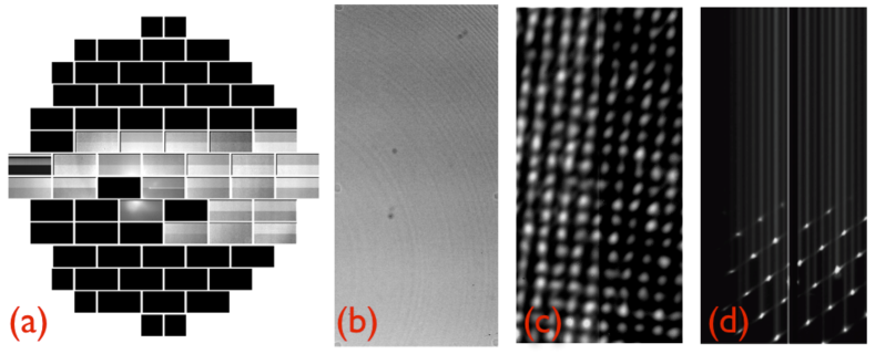
In addition to the image types expected in regular DES operations (biases, darks, flat fields and science fields) we also simulated “focus” images by performing traditional focus sweep sequences and “trail” images by reading out with the shutter open. The focus images were used to test the hexapod movements, but DES will not rely on focus sequences to maintain focus. DECam has dedicated focus chips at the edges of the focal plane and will analyze their images to adjust the focus and alignment from one image to the next. The trail images were used to test the vibrations requirements.
5 Results
5.1 Verification of technical requirements
Data obtained during the testing of the imager on the telescope simulator were used to verify the DECam technical requirements [30]. The tests were detailed in a report [31] and a summary of the results is presented in Table 1.
| ID | DESCRIPTION | REQUIREMENT | MEASUREMENT |
|---|---|---|---|
| TG6 | Internal charged particle rate | events/cm2/min | 2.7 events/cm2/min |
| TG8 | Function in all orientations | Yes | Yes(a) |
| TG10 | Function in all expected environment | Yes | Yes(b) |
| TO10 | Flat Focal Plane peak to peak variations | m | m (c) |
| TD1 | Nonlinearity | ||
| TD2 | Full well capacity | k | k |
| TD4 | Readout rate | 17 seconds | 17 seconds |
| TD9 | CCD temperature stability with time | K over 12 h | K over 3 days |
| TD11 | CCD temperature stability across FP | C | C |
| TD12 | CCD readout noise | ||
| TOM1 | FP mean temperature | C | C (c) |
| TOM2 | FP temperature stability with time | K over 12 h | K over 3 days |
| TOM3 | FP temperature stability across FP | C | C |
| TOM4 | Dewar vacuum before cooling | mtorr | mtorr |
| TOM5 | Dewar vacuum after cooling | mtorr | mtorr |
| TOM6 | Operation time w/o human intervention | h | 1 week |
| TOM8 | FP cooling time | h | 6h |
| TOM9 | Dewar warm up time | h | 12h |
| TOM12 | Vibration due to vacuum/cooling | m | m |
| TOM13 | Alignment between FP and C5 | m | m |
| TOM21 | Horizontal translation accuracy | m | m |
| TOM24 | Filter placement accuracy | mm | m |
| TGFA1 | Guider update rate | Hz | 1.21Hz |
| TGFA5 | Guide CCD readout noise | 9 | |
| TGFA6 | Guider region-of-interest capability | Yes | Yes |
| (a) Tested at 5 rotation angles (0,45,90,117,131 deg) with respect to the optical axis and 2 elevation angles (Zenith and 7 deg). | |||
| (b) Tested at environment temperatures between 13 and 38 C and relative air humidity between 15 and 45 percent. | |||
| (c) Measured with science grade CCDs after the imager was taken down from the telescope simulator. | |||
The technical requirements are divided into groups: General (TG), Optical (TO), CCD detectors (TD), Opto-mechanical (TOM), Guider, Focus and Alignment (TGFA). The results show that DECam meets all the requirements tested. Other requirements, such as those involving optics elements, will be tested at CTIO. Based on these results, the imager was accepted and the shipping process has started. All the DECam components are expected to have arrived at CTIO by December 2011.
5.2 Mock observing run
By the end of the DECam test cycle on the telescope simulator it became clear that we had made significant progress towards a fully integrated system. The mock observing run [32] was a comprehensive integration test, scheduled for Feb 14-18 2011, in order to verify that the full system is operational by successfully simulating 4 nights of DES main survey and supernova observations. This test allowed us to bring together new functionalities of SISPI, gather feedback on GUIs, verify that all images produced have headers useful for analysis, train people to operate the data acquisition system and identify improvements to be made before we move to CTIO. Observers followed the Observers’ Guide, a document drafted for the mock observing run and will serve as a baseline for the DES Observers’ Guide. Of the various components that provide input for SISPI, the Focal Plane was the one we could fully test. The Data Transfer System was simulated by transferring images from one machine to another in our own network, but transfers to remote locations were not tested. Other components such as the Telescope Control System and Cloud Camera were not simulated. Data Management processing of the images was not a goal for this test.
We operated the system as if we were taking DES data at the mountain top, starting with calibration images such as biases, darks and flats in the various filters and proceeding to science images. We exercised both survey and supernova modes using ObsTac, the autopilot responsible for populating the exposure queue according to the survey strategy. We verified that the exposures were taken in survey mode when the conditions were set to photometric and that ObsTac would automatically switch to supernova mode when conditions changed to non-photometric, as expected. Image Health, the diagnostics tool, provided basic information about the noise level in real time. The images taken generated entries in the Exposure Database Table, the Electronic Logbook and, in case of problems, the Alarms Database. The Guider Control System was used to perform regions-of-interest readouts of the guider chips, but we did not test any guiding algorithm because our setup did not simulate the telescope guiding capability. In addition to the Image Health realtime diagnostics, we tested the Quick Reduce system. Quick Reduce processes selected images from the Exposure Table, providing a higher level of diagnostics to the observers. We exercised the operations model in which we have 2 observers per night. Although experienced observers could operate the system without a partner, the 2 observers model has proven to be a very efficient way to run the system, allowing for frequent checks of the various diagnostic tools and decision making without unnecessary delay between exposures.
Overall the system worked very well with only minor glitches from which we could recover easily and, although some functionalities were not available for testing, we were able to simulate the observing routine and follow the observing plan very closely. Besides the data that was collected by the SISPI software, the observers were asked to provide feedback regarding the use of the software and other aspects of the observing in order to provide guidance towards future development. These were gathered into the mock observing end of run report [33].
6 Conclusion
The installation of DECam at CTIO is imminent. To verify that the DECam imager meets the key requirements prior to shipping and in order to minimize the time needed for commissioning we built a telescope simulator and performed extensive tests which included a mock observing run according to the DES observing strategy. Table 1 shows that DECam meets all of the requirements tested. As we performed a comprehensive test of the system with all the core components working together for the first time, we were able to verify the readiness of each component and test them in conditions close to what we will experience at the mountain top. This allows us to assess the current status and plan ahead for the next stage of the project.
In the process of performing the mock observing run, a high level of interaction between the SISPI team, the DECam team and the collaboration at large was achieved. Some of the observers were not familiar with the system prior to the mock observing run and were glad to have the opportunity to learn through this experience. On the other hand, the SISPI and DECam team benefited from this interaction through very positive feedback aimed at the observers needs. Also, in the process of preparation for the mock observing run, the overall integration and reliability of the system improved at a fast pace. As a result, observers were able to operate the system with only minor glitches and by the end of the run, the team was confident that commissioning will occur smoothly and DES will be ready to start its first observing season in September 2012.
Acknowledgements
Funding for the DES Projects has been provided by the U.S. Department of Energy, the U.S. National Science Foundation, the Ministry of Science and Education of Spain, the Science and Technology Facilities Council of the United Kingdom, the Higher Education Funding Council for England, the National Center for Supercomputing Applications at the University of Illinois at Urbana-Champaign, the Kavli Institute of Cosmological Physics at the University of Chicago, Financiadora de Estudos e Projetos, Fundação Carlos Chagas Filho de Amparo à Pesquisa do Estado do Rio de Janeiro, Conselho Nacional de Desenvolvimento Científico e Tecnológico and the Ministério da Ciência e Tecnologia, the Deutsche Forschungsgemeinschaft and the Collaborating Institutions in the Dark Energy Survey.
The Collaborating Institutions are Argonne National Laboratories, the University of California at Santa Cruz, the University of Cambridge, Centro de Investigaciones Energeticas, Medioambientales y Tecnologicas-Madrid, the University of Chicago, University College London, DES-Brazil, Fermilab, the University of Edinburgh, the University of Illinois at Urbana-Champaign, the Institut de Ciencies de l’Espai (IEEC/CSIC), the Institut de Fisica d’Altes Energies, the Lawrence Berkeley National Laboratory, the Ludwig-Maximilians Universität and the associated Excellence Cluster Universe, the University of Michigan, the National Optical Astronomy Observatory, the University of Nottingham, the Ohio State University, the University of Pennsylvania, the University of Portsmouth, SLAC, Stanford University, the University of Sussex, and Texas A & M University.
References
- [1] T. Abbott, et al., The Dark Energy Survey (2005). arXiv:astro-ph/0510346.
- [2] J. Annis, et al., Constraining Dark Energy with DES: theoretical challenges (2005). arXiv:astro-ph/0510195.
- [3] J. Annis, et al., Dark Energy studies: challenges to computational cosmology (2005). arXiv:astro-ph/0510194.
- [4] A. Albrecht, et al., Report of the Dark Energy Task Force (2006). arXiv:astro-ph/0609591.
- [5] S. Thomas, F. Abdalla, O. Lahav, PRL 106 (2011) 241301. arXiv:1012.2272.
- [6] B. Flaugher, Proc. SPIE 6269 (2006) 62692C.
- [7] H. Cease, et al., Proc. SPIE 7014 (2008) 70146N.
- [8] G. Derylo, et al., Proc. SPIE 7739 (2010) 77393M.
- [9] B. Flaugher, et al., Proc. SPIE 7735 (2010) 77350D.
- [10] D. DePoy, et al., Proc. SPIE 7014 (2008) 70140E.
- [11] K. Honscheid, et al., Proc. ICHEP (2008). arXiv:0810.3600.
- [12] S. Holland, et al., IEEE Transactions on Electron Devices 50 (2003) 225.
- [13] J. Estrada, et al., Proc. SPIE 7735 (2010) 77351R.
- [14] T. Abbott, et al., Proc. SPIE 6267 (2006) 77353I.
- [15] H. T. Diehl, et al., Proc. SPIE 7735 (2010) 77353I.
- [16] H. T. Diehl, The Dark Energy Survey Camera, Phys. Proc. TIPP (2011).
- [17] D. Kubik, CCD testing for DECam, Phys. Proc. TIPP (2011).
- [18] T. Shaw, DECam Readout Electronics, Phys. Proc. TIPP (2011).
- [19] H. Cease, et al., Proc. SPIE 7739 (2010) 77393N.
- [20] G. Derylo, H. T. Diehl, J. Estrada, Proc. SPIE 6276 (2006) 627608.
- [21] J. Estrada, et al., Proc. SPIE 6269 (2006) 62693K.
- [22] H. T. Diehl, et al., Proc. SPIE 7021 (2008) 702107.
- [23] D. Kubik, et al., Proc. SPIE 7735 (2010) 77355C.
- [24] J. Castilla, et al., Proc. SPIE 7735 (2010) 77352O.
- [25] T. Shaw, et al., Proc. SPIE 7735 (2010) 77353G.
- [26] S. Kent, et al., Proc. SPIE 6269 (2006) 626937.
- [27] K. Honscheid, et al., Proc. SPIE 7019 (2008) 701911.
- [28] J. J. Mohr, et al., Proc. SPIE 7016 (2008) 70160L. arXiv:0807.2515.
- [29] J. Hao, et al., Proc. SPIE 7735 (2010) 77353U. arXiv:1010.6072.
- [30] T. Abbott, et al., DECam Technical Specifications and Requirements, des-docdb: 806 (2009) , DES internal document.
- [31] M. Estrada, J. Hao, Checking the requirements on the DECam imager, des-docdb: 5327 (2011) , DES internal document.
- [32] M. Soares-Santos, W. Wester, DES mock observing run plan, des-docdb: 5267 (2011) , DES internal document.
- [33] M. Soares-Santos, W. Wester, DES mock observing end of run report, des-docdb: 5509 (2011) , DES internal document.