Saying Hello World with UML-RSDS – A Solution to the 2011 Instructive Case
Abstract
In this paper we apply the UML-RSDS notation and tools to the “Hello World” case studies and explain the underlying development process for this model transformation approach.
1 Specification of model transformations
In UML-RSDS a transformation specification is written in first-order logic and OCL, and consists of the following predicates:
-
1.
A global specification, , of a model transformation, expresses in a platform-independent manner the overall effect of the transformation, as a relation between the source and target models. It is intended to hold true at termination of the transformation.
-
2.
A predicate expresses the assumptions made about the source and target models at the start of the transformation, for example, that the target model is empty and that the source model is syntactically correct wrt the source language.
The specification is therefore independent of any specific model transformation implementation language, and can be used as the basis for development in many such languages. By making explicit the semantic assumptions on source and target models, the specification assists in the verification (formal or informal) of model transformations.
can often be written in conjunctive-implicative form [3], as a conjunction of constraints of the form
where is a source language entity and is a target language entity. This pattern is applicable to re-expression transformations such as model migrations, and to abstraction and refinement transformations.
The patterns assist in the derivation of explicit PSM designs from the specification, consisting of a sequence of phases, which apply specific rules or operations to achieve the specification constraints. Provided that the updates defined in do not affect the data read in or , and that the extent of is fixed throughout the transformation , then a constraint of the above form can be implemented by an iteration
for dowhere implements the constraint for a particular object.
This iteration constitutes a single phase in the design. The possible orderings of phases are determined by defining a partial order over the target language entities: if is used in to define a feature of (or a feature of a subclass of ). Any phase that creates instances must therefore be preceded by all phases that create instances.
The restriction is termed the non-interference condition.
The iterative phase activities derived from the constraints are also terminating and they establish the truth of their corresponding constraint, by construction. The PSM design is derived from the constraints, together with an executable Java implementation, using the UML-RSDS toolset [2]. The resulting executable is a stand-alone implementation of the transformation, operating upon simple text format files defining input and output models.
2 Simple transformation tasks
Here we give the specifications and implementations of the simple transformation tasks in [1]. All of these tasks satisfy the restrictions described above, so they can be specified and designed directly in UML-RSDS.
2.1 Hello world transformation
This has the global specification ( predicate):
This predicate is coded in UML-RSDS as the only postcondition
of a use case which represents the transformation. From this an implementation is automatically generated in Java.
2.2 Graph properties
Figure 2 shows the basic graph metamodel in the UML-RSDS tools, and the generated design and Java code of the specification.
We assume that the following constraint of the source model holds:
The queries are simple examples of abstraction transformations, and can be specified as follows:
The constraint
on expresses that for each graph there is a result object recording the number of nodes in the graph. An operation is generated to implement the constraint.
Likewise for the other queries:
counts the number of looping edges in each graph, and is implemented by an operation .
counts the number of dangling edges and is implemented by an iteration of an operation on graphs.
counts the number of nodes that are not the source or target of any edge. denotes set subtraction and set union. This is implemented by an operation .
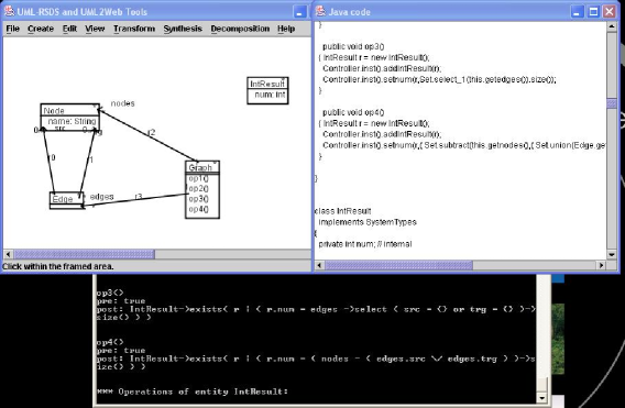
We extend the final query problem by defining an auxiliary entity which records the 3-cycles in the graph (Figure 1).

The specification of this transformation then defines how unique elements of are derived from the graph, and returns the cardinality of this type in the end state of the transformation:
Both constraints are on .
The order of nodes in a cycle is not distinguished by , if this was required then should be ordered (a sequence). Because of , each three-cycle will consist of nodes in a single graph. The unique existential quantifier specifies that there must exist exactly one object satisfying the quantified properties, ie, duplicated cycles are not included in .
Each constraint is refined by a specific phase in the design. The quantifier is implemented by checking that there is no existing with the required property, before creating such an element.
An alternative approach would be to evaluate the set of three cycles in a single expression:
but we consider that the approach using is more clear.
2.3 Reverse edges
The global specification for this transformation is:
on . The suffix denotes the value of the expression at the start of the transformation. This is the usual style of specification for update-in-place transformations.
2.4 Simple migration
The metamodels for this re-expression transformation are shown in Figure 3, together with extracts from example input and output models (on the left and right hand sides, respectively).
We make the additional assumption that the target model is empty at the start of the transformation:
We can specify this transformation by three constraints, defined as the postconditions of a single use case of the system:
is a constraint on , and on . denotes the set of objects with primary key value in the set .
is a constraint on . A design can be automatically generated from these constraints, this implements each constraint by a separate phase in a three-phase algorithm. The ordering of the phases follows from the ordering of the entities in the target language, based upon the dependencies between these entities in the specification constraints ( instances depend upon instances, etc).
2.5 Delete nodes
The global specification of this update-in-place transformation can be written as:
on . The predicate also serves as the definition of an operation of that implements the transformation. Since edges depend on nodes, edges are deleted before nodes (the reverse to the ordering used in construction of a model).
2.6 Insert transitive edges
This can be considered as a simple example of a quality-improvement model transformation. Such transformations are typically update-in-place transformations, and have an associated quality measure on the models, used to show termination of the transformation. The transformation aims to reduce to 0 in the target model. In this case is the number of pairs of distinct non-dangling edges , of the source model with and with no existing edge from to .
Under the assumption that there are not already any duplicate edges in the graph:
the specification of this transformation can be written as:
on . This satisfies the non-interference condition (since the created edges are distinct and are not included in the sets of edges being iterated over), so permitting an implementation using fixed iterations. If instead the transitive closure of was required, would use instead of @, and a more complex implementation strategy would be required, using repeated iteration until a fixed point is reached [3].
3 Conclusion
We have shown that UML-RSDS can specify the case study transformations in a direct manner as high-level specifications, from which designs and executable implementations can be automatically generated. UML-RSDS has the advantage of using standard UML and OCL notations to specify transformations, reducing the cost of learning a special-purpose transformation language. Our method also has the advantage of making explicit all assumptions on models (eg, above) and providing global specifications (, ) of transformations, independent of specific rules.
Further work includes linking UML-RSDS to Eclipse/EMF to enable the use of ecore metamodels and import/export of Eclipse/EMF models.
References
- [1] S. Mazanek, Hello World: an instructive case for the Transformation Tool Contest, in [5], 2011.
- [2] K. Lano, S. Kolahdouz-Rahimi, Specification and Verification of Model Transformations using UML-RSDS, IFM 2010.
- [3] K. Lano, S. Kolahdouz-Rahimi, Model Transformation Design Patterns, ICSEA 2011.
- [4] K. Lano, S. Kolahdouz-Rahimi, Model-Driven Development of Model Transformations, ICMT 2011.
- [5] Van Gorp, Pieter, Mazanek, Steffen, and Rose, Louis, TTC 2011: Fifth Transformation Tool Contest, Zürich, Switzerland, June 29-30 2011, Post-Proceedings, EPTCS, 2011.
Appendix A: Transforming specific models
Source and target metamodels are defined using the visual class diagram editor of UML-RSDS (Figures 2 and 3). Metamodels cannot contain multiple inheritance, and all non-leaf classes must be abstract. Metamodels can be saved to a file by the command.
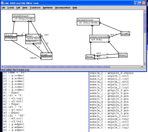
Source models can be defined in text files, which are then read by the executable implementation of the transformation metaclass, in a textual form. For example, a test model of the simple graph metamodel can be defined as follows:
g : Graph
n1 : Node
n1.name = "n1"
n1 : g.nodes
n2 : Node
n2.name = "n2"
n2 : g.nodes
e : Edge
n1 : e.src
n2 : e.trg
e : g.edges
This defines a single edge from the first to the second node. Alternative models can be defined in a similar way.
The UML-RSDS toolset is located at http://www.dcs.kcl.ac.uk/staff/kcl/uml2web. UML-RSDS can be executed by the command java UmlTool. The directory output is used to store metamodels, input and output models, and the generated Java code. The command loads a metamodel from a file (eg, for the migration metamodel). The command generates the Java executable of a transformation, this generated executable is the Controller.java file in the directory. This can be compiled and used independently of the toolset.