Current address: ]Albert-Einstein-Institut, Max-Planck-Institut für Gravitationsphysik, D-30167 Hannover, Germany
Current address: ]KLA-Tencor, Milpitas, California 95035, USA
Current address: ]University of Massachusetts–Amherst, Amherst, MA 01003, USA
Current address: ]École Polytechnique, 91128 Palaiseau Cedex, France
Current address: ]The University of Texas at Brownsville, Brownsville, TX 78520, USA
Current address: ]LIGO - California Institute of Technology, Pasadena, CA 91125, USA
Current address: ]Nasa Langley Research Center, Hampton, VA 23666, USA
Characterization of thermal effects in the Enhanced LIGO Input Optics
Abstract
We present the design and performance of the LIGO Input Optics subsystem as implemented for the sixth science run of the LIGO interferometers. The Initial LIGO Input Optics experienced thermal side effects when operating with 7 W input power. We designed, built, and implemented improved versions of the Input Optics for Enhanced LIGO, an incremental upgrade to the Initial LIGO interferometers, designed to run with 30 W input power. At four times the power of Initial LIGO, the Enhanced LIGO Input Optics demonstrated improved performance including better optical isolation, less thermal drift, minimal thermal lensing and higher optical efficiency. The success of the Input Optics design fosters confidence for its ability to perform well in Advanced LIGO.
I Introduction
The field of ground-based gravitational-wave (GW) physics is rapidly approaching a state with a high likelihood of detecting GWs for the first time in the latter half of this decade. Such a detection will not only validate part of Einstein’s general theory of relativity, but initiate an era of astrophysical observation of the universe through GWs. Gravitational waves are dynamical strains in space-time, , that travel at the speed of light and are generated by non-axisymmetric acceleration of mass. A first detection is expected to witness an event such as a binary black hole/neutron star merger (Abadie2010Predictions, ).
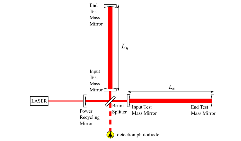
The typical detector configuration used by current generation gravitational-wave observatories is a power-recycled Fabry-Perot Michelson laser interferometer featuring suspended test masses in vacuum as depicted in Figure 1. A diode-pumped, power amplified, and intensity and frequency stabilized Nd:YAG laser emits light at nm. The laser is directed to a Michelson interferometer whose two arm lengths are set to maintain destructive interference of the recombined light at the anti-symmetric (AS) port. An appropriately polarized gravitational wave will differentially change the arm lengths, producing signal at the AS port proportional to the GW strain and the input power. The Fabry-Perot cavities in the Michelson arms and a power recycling mirror (RM) at the symmetric port are two modifications to the Michelson interferometer that increase the laser power in the arms and therefore improve the detector’s sensitivity to GWs.
A network of first generation kilometer scale laser interferometer gravitational-wave detectors completed an integrated 2-year data collection run in 2007, called Science Run 5 (S5). The instruments were: the American Laser Interferometer Gravitational-wave Observatories (LIGO)(Abbott2009LIGO, ), one in Livingston, LA with 4 km long arms and two in Hanford, WA with 4 km and 2 km long arms; the 3 km French-Italian detector VIRGO(Acernese2008Virgo, ) in Cascina, Italy; and the 600 m German-British detector GEO(Luck2006Status, ) located near Hannover, Germany. Multiple separated detectors increase detection confidence through signal coincidence and improve source localization via waveform reconstruction.
The first generation of LIGO, now known as Initial LIGO, achieved its design goal of sensitivity to GWs in the 40–7000 Hz band, including a record strain sensitivity of at 155 Hz. However, only nearby sources produce enough GW strain to appear above the noise level of Initial LIGO and no gravitational wave has yet been found in the S5 data. A second generation of LIGO detectors, Advanced LIGO, has been designed to be at least an order of magnitude more sensitive at several hundred Hz and above and to give an impressive increase in bandwidth down to 10 Hz. Advanced LIGO is expected to open the field of GW astronomy through the detection of many events per year (Abadie2010Predictions, ). To test some of Advanced LIGO’s new technologies and to increase the chances of detection through a more sensitive data taking run, an incremental upgrade to the detectors was carried out after S5 (Adhikari2006Enhanced, ). This project, Enhanced LIGO, culminated with the S6 science run from July 2009 to October 2010. Currently, construction of Advanced LIGO is underway. Simultaneously, VIRGO and GEO are both undergoing their own upgrades (Acernese2008Virgo, ; Luck2010Upgrade, ).
The baseline Advanced LIGO design (AdvLigoSysDesign, ) improves upon Initial LIGO by incorporating improved seismic isolation (Robertson2004Seismic, ), the addition of a signal recycling mirror at the output port (Meers1988Recycling, ), homodyne readout, and an increase in available laser power from 8 W to 180 W. The substantial increase in laser power improves the shot-noise-limited sensitivity, but introduces a multitude of thermally induced side effects that must be addressed for proper operation.
Enhanced LIGO tested portions of the Advanced LIGO designs so that unforeseen difficulties could be addressed and so that a more sensitive data taking run could take place. An output mode cleaner was designed, built and installed, and DC readout of the GW signal was implemented (Fricke2011DC, ). An Advanced LIGO active seismic isolation table was also built, installed, and tested (KisselThesis, , Chapter 5). In addition, the 10 W Initial LIGO laser was replaced with a 35 W laser (Frede2007Fundamental, ). Accompanying the increase in laser power, the test mass Thermal Compensation System (Willems2009Thermal, ), the Alignment Sensing and Control (DooleyAngular, ), and the Input Optics were modified.
This paper reports on the design and performance of the LIGO Input Optics (IO) subsystem in Enhanced LIGO, focusing specifically on its operational capabilities as the laser power is increased to 30 W. Substantial improvements in the IO power handling capabilities with respect to Initial LIGO performance are seen. The paper is organized as follows. First, in Section II we define the role of the IO subsystem and detail the function of each of the major IO subcomponents. Then, in Section III we describe thermal effects which impact the operation of the IO and summarize the problems experienced with the IO in Initial LIGO. In Section IV we present the IO design for Advanced LIGO in detail and describe how it addresses these problems. Section V presents the performance of the prototype Advanced LIGO IO design as tested during Enhanced LIGO. Finally, we extrapolate from these experiences in Section VI to discuss the expected IO performance in Advanced LIGO. The paper concludes with a summary in Section VII.
II Function of the Input Optics
The Input Optics is one of the primary subsystems of the LIGO interferometers. Its purpose is to deliver an aligned, spatially pure, mode-matched beam with phase-modulation sidebands to the power-recycled Fabry-Perot Michelson interferometer. The IO also prevents reflected or backscattered light from reaching the laser and distributes the reflected field from the interferometer (designated the reflected port) to photodiodes for sensing and controlling the length and alignment of the interferometer. In addition, the IO provides an intermediate level of frequency stabilization and must have high overall optical efficiency. It must perform these functions without limiting the strain sensitivity of the LIGO interferometer. Finally, it must operate robustly and continuously over years of operation. The conceptual design is found in Ref. (Camp1996InputOutput, ).
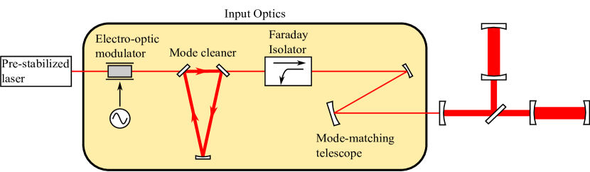
As shown in Fig. 2, the IO subsystem consists of four principle components located between the pre-stabilized laser and the power recycling mirror:
-
•
electro-optic modulator (EOM)
-
•
mode cleaner cavity (MC)
-
•
Faraday isolator (FI)
-
•
mode-matching telescope (MMT)
Each element is a common building block of many optical experiments and not unique to LIGO. However, their roles specific to the successful operation of interferometry for gravitational-wave detection are of interest and demand further attention. Here, we briefly review the purpose of each of the IO components; further details about the design requirements are in Ref. (Camp1997Input, ).
II.1 Electro-optic modulator
The Length Sensing and Control (LSC) and Angular Sensing and Control (ASC) subsystems require phase modulation of the laser light at RF frequencies. This modulation is produced by an EOM, generating sidebands of the laser light which act as references against which interferometer length and angle changes are measured (Fritschel2001Readout, ). The sideband light must be either resonant only in the recycling cavity or not resonant in the interferometer at all. The sidebands must be offset from the carrier by integer multiples of the MC free spectral range to pass through the MC.
II.2 Mode cleaner
Stably aligned cavities, limited non-mode-matched (junk) light, and a frequency and amplitude stabilized laser are key features of any ultra sensitive laser interferometer. The MC, at the heart of the IO, plays a major role.
A three-mirror triangular ring cavity, the MC suppresses laser output not in the fundamental TEM00 mode, serving two major purposes. It enables the robustness of the ASC because higher order modes would otherwise contaminate the angular sensing signals of the interferometer. Also, all non-TEM00 light on the length sensing photodiodes, including those used for the GW readout, contributes shot noise but not signal and therefore diminishes the signal to noise ratio. The MC is thus largely responsible for achieving an aligned, minimally shot-noise-limited interferometer.
The MC also plays an active role in laser frequency stabilization (Fritschel2001Readout, ), which is necessary for ensuring that the signal at the anti-symmetric port is due to arm length fluctuations rather than laser frequency fluctuations. In addition, the MC passively suppresses beam jitter at frequencies above 10 Hz.
II.3 Faraday isolator
Faraday isolators are four-port optical devices which utilize the Faraday effect to allow for non-reciprocal polarization switching of laser beams. Any backscatter or reflected light from the interferometer (due to impedance mismatch, mode mismatch, non-resonant sidebands, or signal) needs to be diverted to protect the laser from back propagating light, which can introduce amplitude and phase noise. This diversion of the reflected light is also necessary for extracting length and angular information about the interferometer’s cavities. The FI fulfils both needs.
II.4 Mode-matching telescope
The lowest-order MC and arm cavity spatial eigenmodes need to be matched for maximal power buildup in the interferometer. The mode-matching telescope is a set of three suspended concave mirrors between the MC and interferometer that expand the beam from a radius of 1.6 mm at the MC waist to a radius of 33 mm at the arm cavity waist. The MMT should play a passive role by delivering properly shaped light to the interferometer without introducing beam jitter or any significant aberration that can reduce mode coupling.
III Thermal problems in Initial LIGO
The Initial LIGO interferometers were equipped with a 10 W laser, yet operated with only 7 W input power due to power-related problems with other subsystems. The EOM was located in the 10 W beam and the other components experienced anywhere up to 7 W power. The 7 W operational limit was not due to the failure of the IO; however, many aspects of the IO performance did degrade with power.
One of the primary problems of the Initial LIGO IO (Adhikari1998Input, ) was thermal deflection of the back propagating beam due to thermally-induced refractive index gradients in the FI. A significant beam drift between the interferometer’s locked and unlocked states led to clipping of the reflected beam on the photodiodes used for length and alignment control (see Fig. 3). Our measurements determined a deflection of approximately 100 µrad/W in the FI. This problem was mitigated at the time by the design and implementation of an active beam steering servo on the beam coming from the isolator.
There were also known limits to the power the IO could sustain. Thermal lensing in the FI optics began to alter significantly the beam mode at powers greater than 10 W, leading to a several percent reduction in mode matching to the interferometer (UFLIGOGroup2006Upgrading, ). Additionally, absorptive FI elements would create thermal birefringence, degrading the optical efficiency and isolation ratio with power (Khazanov1999Investigation, ). The Initial LIGO New Focus EOMs had an operational power limit of around 10 W. There was a high risk of damage to the crystals under the stress of the 0.4 mm radius beam. Also, anisotropic thermal lensing with focal lengths as severe as 3.3 m at 10 W made the EOMs unsuitable for much higher power. Finally, the MC mirrors exhibited high absorption (as much as 24 ppm per mirror)–enough that thermal lensing of the MC optics at Enhanced LIGO powers would induce higher order modal frequency degeneracy and result in a power-dependent mode mismatch into the interferometer (Bullington2008Modal, ; Arain2007Note, ). In fact, as input power increased from 1 W to 7 W the mode matching decreased from 90% to 83%.
In addition to the thermal limitations of the Initial LIGO IO, optical efficiency in delivering light from the laser into the interferometer was not optimal. Of the light entering the IO chain, only 60% remained by the time it reached the power recycling mirror. Moreover, because at best only 90% of the light at the recycling mirror was coupled into the arm cavity mode, room was left for improvement in the implementation of the MMT.
IV Enhanced LIGO Input Optics Design
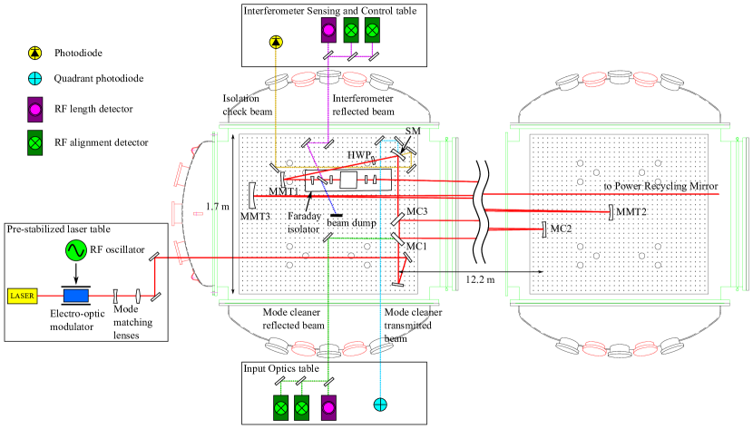
The Enhanced LIGO IO design addressed the thermal effects that compromised the performance of the Initial LIGO IO, and accommodated up to four times the power of Initial LIGO. Also, the design was a prototype for handling the 180 W laser planned for Advanced LIGO. Because the adverse thermal properties of the Initial LIGO IO (beam drift, birefringence, and lensing) are all attributable primarily to absorption of laser light by the optical elements, the primary design consideration was finding optics with lower absorption (UFLIGOGroup2006Upgrading, ). Both the EOM and the FI were replaced for Enhanced LIGO. Only minor changes were made to the MC and MMT. A detailed layout of the Enhanced LIGO IO is shown in Figure 3.
IV.1 Electro-optic modulator design
We replaced the commercially-made New Focus 4003 resonant phase modulator of Initial LIGO with an in-house EOM design and construction. Both a new crystal choice and architectural design change allow for superior performance.
The Enhanced LIGO EOM design uses a crystal of rubidium titanyl phosphate (RTP), which has at most 1/10 the absorption coefficient at 1064 nm of the lithium niobate (LiNbO3) crystal from Initial LIGO. At 200 W the RTP should produce a thermal lens of 200 m and higher order mode content of less than 1%, compared to the 3.3 m lens the LiNbO3 produces at 10 W. The RTP has a minimal risk of damage, because it has both twice the damage threshold of LiNbO3 and is subjected to a beam twice the size of that in Initial LIGO. RTP and LiNbO3 have similar electro-optic coefficients. Also, RTP’s anisotropy is 50% smaller. Table 1 compares the properties of most interest of the two crystals.
| units | LiNbO3 | RTP | |
|---|---|---|---|
| damage threshold | MW/cm2 | 280 | |
| absorption coeff. at 1064 nm | ppm/cm | ||
| electro-optic coeff. () | pm/V | 306 | 239 |
| 10-6/K | 5.4 | 2.79 | |
| 10-6/K | 37.9 | 9.24 |
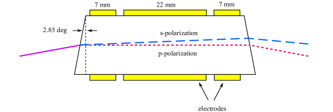
We procured the RTP crystals from Raicol and packaged them into specially-designed, custom-built modulators. The crystal dimensions are mm and their faces are wedged by and anti-reflection (AR) coated. The wedge serves to separate the polarizations and prevents an etalon effect, resulting in a suppression of amplitude modulation. Only one crystal is used in the EOM in order to reduce the number of surface reflections. Three separate pairs of electrodes, each with its own resonant LC circuit, are placed across the crystal in series, producing the three required sets of RF sidebands: 24.5 MHz, 33.3 MHZ and 61.2 MHz. A diagram is shown in Fig. 4. Reference (Quetschke2008ElectroOptic, ) contains further details about the modulator architecture.

IV.2 Mode cleaner design
The MC is a suspended 12.2 m long triangular ring cavity with finesse =1280 and free spectral range of 12.243 MHz. The three mirror architecture was selected over the standard two mirror linear filter cavity because it acts as a polarization filter and because it eliminates direct path back propagation to the laser (Raab1992Estimation, ). A pick-off of the reflected beam is naturally facilitated for use in generating control signals. A potential downside to the three mirror design is the introduction of astigmatism, but this effect is negligible due to the small opening angle of the MC.
The MC has a round-trip length of 24.5 m. The beam waist has a radius of 1.63 mm and is located between the two 45∘ flat mirrors, MC1 and MC3. See Figure 3. A concave third mirror, MC2, 18.15 m in radius of curvature, forms the far point of the mode cleaner’s isosceles triangle shape. The power stored in the MC is 408 times the amount coupled in, equivalent to about 2.7 kW in Initial LIGO and at most 11 kW for Enhanced LIGO. The peak irradiances are 32 kW/cm2 and 132 kW/cm2 for Initial LIGO and Enhanced LIGO, respectively.
The MC mirrors are 75 mm in diameter and 25 mm thick. The substrate material is fused silica and the mirror coating is made of alternating layers of silica and tantala. In order to reduce the absorption of light in these materials and therefore improve the transmission and modal quality of the beam in the MC, we removed particulate by drag wiping the surface of the mirrors with methanol and optical tissues. The MC was otherwise identical to that in Initial LIGO.
IV.3 Faraday isolator design
The Enhanced LIGO FI design required not only the use of low absorption optics, but additional design choices to mitigate any residual thermal lensing and birefringence. In addition, trade-offs between optical efficiency in the forward direction, optical isolation in the backwards direction, and feasibility of physical access of the return beam for signal use were considered. The result is that the Enhanced LIGO FI needed a completely new architecture and new optics compared to both the Initial LIGO FI and commercially available isolators.
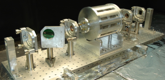
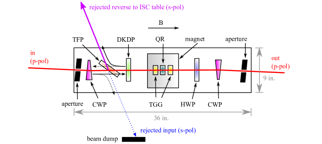
Figure 5 shows a photograph and a schematic of the Enhanced LIGO FI. It begins and ends with low absorption calcite wedge polarizers (CWP). Between the CWPs is a thin film polarizer (TFP), a deuterated potassium dihydrogen phosphate (DKDP) element, a half-wave plate (HWP), and a Faraday rotator. The rotator is made of two low absorption terbium gallium garnet (TGG) crystals sandwiching a quartz rotator (QR) inside a 7-disc magnet with a maximum field strength of 1.16 T. The forward propagating beam upon passing through the TGG, QR, TGG, and HWP elements is rotated by . In the reverse direction, the rotation through HWP, TGG, QR, TGG is . The TGG crystals are non-reciprocal devices while the QR and HWP are reciprocal.
IV.3.1 Thermal birefringence
Thermal birefringence is addressed in the Faraday rotator by the use of the two TGG crystals and one quartz rotator rather than the typical single TGG (Khazanov2000Suppression, ). In this configuration, any thermal polarization distortions that the beam experiences while passing through the first TGG rotator will be mostly undone upon passing through the second. The multiple elements in the magnet required a larger magnetic field than in Initial LIGO. The 7-disc magnet is 130 mm in diameter and 132 mm long and placed in housing 155 mm in diameter and 161 mm long. The TGG diameter is 20 mm.
IV.3.2 Thermal lensing
Thermal lensing in the FI is addressed by including DKDP, a negative material, in the beam path. Absorption of light in the DKDP results in a de-focusing of the beam, which partially compensates for the thermal focusing induced by absorption in the TGGs (Mueller2002Method, ; Khazanov2004Compensation, ). The optical path length (thickness) of the DKDP is chosen to slightly over-compensate the positive thermal lens induced in the TGG crystals, anticipating other positive thermal lenses in the system.
IV.3.3 Polarizers
The polarizers used (two CWPs and one TFP) each offer advantages and disadvantages related to optical efficiency in the forward-propagating direction, optical isolation in the reflected direction, and thermal beam drift. The CWPs have very high extinction ratios () and high transmission ( 99%) contributing to good optical efficiency and isolation performance. However, the angle separating the exiting orthogonal polarizations of light is very small, on the order of 10 mrad. This small angle requires the light to travel relatively large distances before we can pick off the beams needed for interferometer sensing and control. In addition, thermally induced index of refraction gradients due to the 4.95∘ wedge angle of the CWPs result in thermal drift. However, the CWPs for the Enhanced LIGO FI have a measured low absorption of 0.0013 cm-1 with an expected thermal lens of 60 m at 30 W and drift of less than 1.3 µrad/W (UFLIGOGroup2006Upgrading, ).
The advantages of the thin film polarizer over the calcite wedge polarizer are that it exhibits negligible thermal drift when compared with CWPs and it operates at the Brewster angle of 55∘, thus diverting the return beam in an easily accessible way. However, the TFP has a lower transmission than the CWP, about 96%, and an extinction ratio of only 103.
Thus, the combination of CWPs and a TFP combines the best of each to provide a high extinction ratio (from the CWPs) and ease of reflected beam extraction (from the TFP). The downsides that remain when using both polarizers are that there is still some thermal drift from the CWPs. Also the transmission is reduced due to the TFP and to the fact that there are 16 surfaces from which light can scatter.
IV.3.4 Heat conduction
Faraday isolators operating in a vacuum environment suffer from increased heating with respect to those operating in air. Convective cooling at the faces of the optical components is no longer an effective heat removal channel, so proper heat sinking is essential to minimize thermal lensing and depolarization. It has been shown that Faraday isolators carefully aligned in air can experience a dramatic reduction in isolation ratio ( 10-15 dB) when placed in vacuum (TheVIRGOCollaboration2008Invacuum, ). The dominant cause is the coupling of the photoelastic effect to the temperature gradient induced by laser beam absorption. Also of importance is the temperature dependence of the Verdet constant–different spatial parts of the beam experience different polarization rotations in the presence of a temperature gradient Barnes1992Variation .
To improve heat conduction away from the Faraday rotator optical components, we designed a housing for the TGG and quartz crystals that provided improved heat sinking to the Faraday rotator. We wrapped the TGGs with indium foil that made improved contact with the housing and we cushioned the DKDP and the HWP with indium wire in their aluminum holders. This has the additional effect of avoiding the development of thermal stresses in the crystals, an especially important consideration for the very fragile DKDP.
IV.4 Mode-matching telescope design
The mode matching into the interferometer (at Livingston) was measured to be at best 90% in Initial LIGO. Because of the stringent requirements placed on the LIGO vacuum system to reduce phase noise through scattering by residual gas, standard opto-mechanical translators are not permitted in the vacuum; it is therefore not possible to physically move the mode matching telescope mirrors while operating the interferometer. Through a combination of needing to move the MMTs in order to fit the new FI on the in-vacuum optics table and additional measurements and models to determine how to improve the coupling, a new set of MMT positions was chosen for Enhanced LIGO. Fundamental design considerations are discussed in Ref. (Delker1997Design, ).
V Performance of the Enhanced LIGO Input Optics
The most convincing figure of merit for the IO performance is that the Enhanced LIGO interferometers achieved low-noise operation with 20 W input power without thermal issues from the IO. Additionally, the IO were operated successfully up to the available 30 W of power. (Instabilities with other interferometer subsystems limited the Enhanced LIGO science run operation to 20 W.)
We present in this section detailed measurements of the IO performance during Enhanced LIGO. Specific measurements and results presented in figures and the text come from Livingston; performance at Hanford was similar and is included in tables summarizing the results.
V.1 Optical efficiency
The optical efficiency of the Enhanced LIGO IO from EOM to recycling mirror was 75%, a marked improvement over the approximate 60% that was measured for Initial LIGO. A substantial part of the improvement came from the discovery and subsequent correction of a 6.5% loss at the second of the in-vacuum steering mirrors directing light into the MC (refer to Fig. 3). A 45∘ reflecting mirror had been used for a beam with an 8∘ angle of incidence. Losses attributable to the MC and FI are described in the following sections. A summary of the IO power budget is found in Table 2.
| Livingston | Hanford | |
|---|---|---|
| MC visibility | 92% | 97% |
| MC transmission | 88% | 90% |
| Composite MC transmission | 81% (72%) | 87% |
| FI transmission | 93% (86%) | 94% (86%) |
| - TFP loss | 4.0% | 2.7% |
| IO efficiency (PSL to RM) | 75% (60%) | 82% |
V.1.1 Mode cleaner losses
The MC was the greatest single source of power loss in both Initial and Enhanced LIGO. The MC visibility,
| (1) |
where is the power injected into the MC and the power reflected, was 92%. Visibility reduction is the result of higher order mode content of and mode mismatch into the MC. The visibility was constant within 0.04% up to 30 W input power at both sites, providing a positive indication that thermal aberrations in the MC and upstream were negligible.
88% of the light coupled into the MC was transmitted. 2.6% of these losses were caused by poor AR coatings on the second surfaces of the MC mirrors. The measured surface microroughness of nm 1998Component caused scatter losses of ppm per mirror inside the MC, or a total of 2.7% losses in transmission.
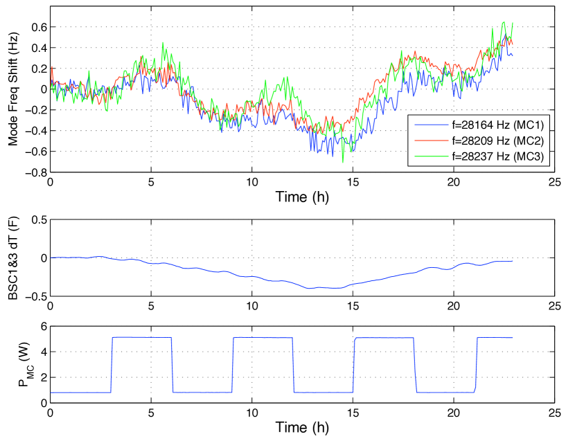
Another source of MC losses is via absorption of heat by particulates residing on the mirror’s surface. We measured the absorption with a technique that makes use of the frequency shift of the thermally driven drumhead eigenfrequencies of the mirror substrate (Punturo2007Mirror, ). The frequency shift directly correlates with the MC absorption via the substrate’s change in Young’s modulus with temperature, . A finite element model (COMSOL COMSOL ) was used to compute the expected frequency shift from a temperature change of the substrate resulting from the mirror coating absorption. The measured eigenfrequencies for each mirror at room temperature are 28164 Hz, 28209 Hz, and 28237 Hz, respectively.
We cycled the power into the MC between 0.9 W and 5.1 W at 3 hour intervals, allowing enough time for a thermal characteristic time constant to be reached. At the same time, we recorded the frequencies of the high Q drumhead mode peaks as found in the mode cleaner frequency error signal, heterodyned down by 28 kHz. See Figure 6. Correcting for ambient temperature fluctuations, we find a frequency shift of 0.043, 0.043, and 0.072 Hz/W. As a result of drag-wiping the mirrors, the absorption decreased for all but one mirror, as shown for both Hanford and Livingston in Table 3.
| mirror | Livingston | Hanford |
|---|---|---|
| MC1 | 2.1 ppm (18.7 ppm) | 5.8 (6.1 ppm) |
| MC2 | 2.0 ppm (5.5 ppm) | 7.6 (23.9 ppm) |
| MC3 | 3.4 ppm (12.8 ppm) | 15.6 (12.5 ppm) |
V.1.2 Faraday isolator losses
The FI was the second greatest source of power loss with its transmission of 93%. This was an improvement over the 86% transmission of the Initial LIGO FI. The most lossy element in the FI is the thin film polarizer, accounting for 4% of total losses. The integrated losses from AR coatings and absorption in the TGGs, CWPs, HWP, and DKDP account for the remaining 3% of missing power.
V.2 Faraday isolation ratio
The isolation ratio is defined as the ratio of power incident on the FI in the reverse direction (the light reflected from the interferometer) to the power transmitted in the reverse direction and is often quoted in decibels: isolation ratio = . We measured the isolation ratio of the FI as a function of input power both in air prior to installation and in situ during Enhanced LIGO operation.
To measure the in-vacuum isolation ratio, we misaligned the interferometer arms so that the input beam would be promptly reflected off of the reflective recycling mirror. This also has the consequence that the FI is subjected to twice the input power. Our isolation monitor was a pick-off of the backwards transmitted beam taken immediately after transmission through the FI that we sent out of a vacuum chamber viewport. Refer to the “isolation check beam” in Fig. 3. The in air measurement was done similarly, except in an optics lab with a reflecting mirror placed directly after the FI.
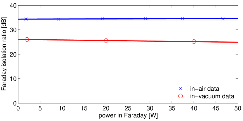
Figure 7 shows our isolation ratio data. Most notably, we observe an isolation decrease of a factor of six upon placing the FI in vacuum, a result consistent with that reported by Ref. (TheVIRGOCollaboration2008Invacuum, ). In air the isolation ratio is a constant 34.46 0.04 dB from low power up to 47 W, and in vacuum the isolation ratio is 26.5 dB at low power. The underlying cause is the absence of cooling by air convection. If we attribute the loss to the TGGs, then based on the change in TGG polarization rotation angle necessary to produce the measured isolation drop of 8 dB and the temperature dependence of the TGG’s Verdet constant, we can put an upper limit of 11 K on the crystal temperature rise from air to vacuum. Furthermore, a degradation of 0.02 dB/W is measured in vacuum.
V.3 Thermal steering
We measured the in situ thermal angular drift of both the beam transmitted through the MC and of the reflected beam from the FI with up to 25 W input power. Just as for the isolation ratio measurement, we misaligned the interferometer arms so that the input beam would be promptly reflected off of the recycling mirror. The Faraday rotator was thus subjected to up to 50 W total and the MC to 25 W.
Pitch and yaw motion of the MC transmitted and interferometer reflected beams were recorded using the quadrant photodiode (QPD) on the IO table and the RF alignment detectors on the Interferometer Sensing and Control table (see Fig. 3). There are no lenses between the MC waist and its measurement QPD, so only the path length between the two were needed to calibrate in radians the pitch and yaw signals on the QPD. The interferometer reflected beam, however, passes through several lenses. Thus, ray transfer matrices and the two alignment detectors were necessary to determine the Faraday drift calibration.
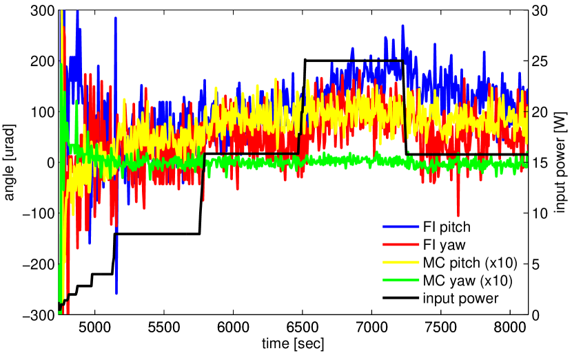
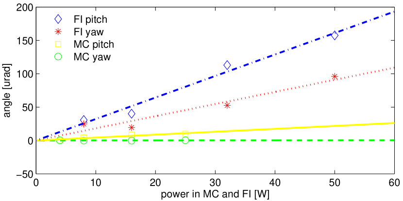
Figure 8 shows the calibrated beam steering data. The angle of the beam out of the MC does not change measurably as a function of input power in yaw (4.7 nrad/W) and changes by only 440 nrad/W in pitch. For the FI, we record a beam drift originating at the center of the Faraday rotator of 1.8 µrad/W in yaw and 3.2 µrad/W in pitch. Therefore, when ramping the input power up to 30 W during a full interferometer lock, the upper limit on the drift experienced by the reflected beam is about 100 µrad. This is a thirty-fold reduction with respect to the Initial LIGO FI and represents a fifth of the beam’s divergence angle, = 490 µrad.
V.4 Thermal lensing
We measured the profiles of both the beam transmitted through the mode cleaner and the reflected beam picked off by the FI at low ( 1 W) and high ( 25 W) input powers to assess the degree of thermal lensing induced in the MC and FI. Again, we misaligned the interferometer arms so that the input beam would be promptly reflected off the recycling mirror. We picked off a fraction of the reflected beam on the Interferometer Sensing and Control table and of the mode cleaner transmitted beam on the IO table (refer to Fig. 3), placed lenses in each of their paths, and measured the beam diameters at several locations on either side of the waists created by the lenses. A change in the beam waist size or position as a function of laser power indicates the presence of a thermal lens.
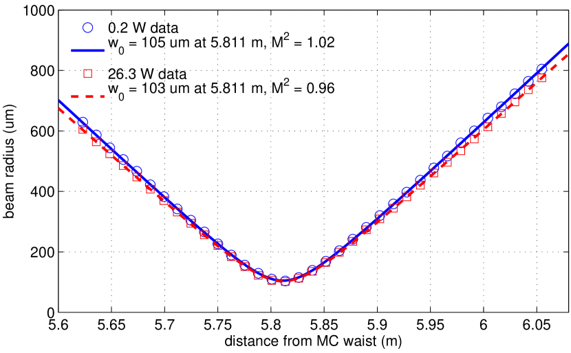
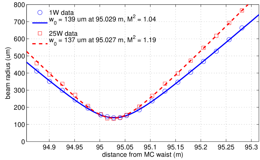
As seen in Fig. 9 and 10, the waists of the two sets of data are collocated: no thermal lens is measured. For the FI, the divergence of the low and high power beams differs, indicating that the beam quality degrades with power. The factor at 1 W is 1.04 indicating the beam is nearly perfectly a TEM00 mode. At 25 W, increases to 1.19, corresponding to increased higher-order-mode content. The percentage of power in higher-order modes depends strongly on the mode order and relative phases of the modes, and thus cannot be determined from this measurement (Kwee2007Laser, ).
The results for the MC are consistent with no thermal lensing. The high and low power beam profiles are within each other’s error bars and well below our requirements.
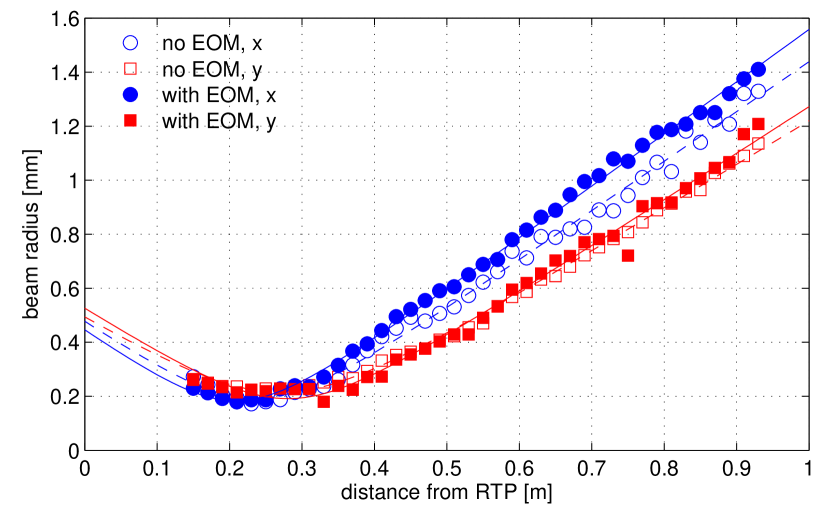
We also measured the thermal lensing of the EOM prior to its installation in Enhanced LIGO by comparing beam profiles of a 160 W beam with and without the EOM in its path. The data for both cross-sections of the beam is presented in Fig. 11. We observe no significant thermal lensing in the y-direction and a small effect in the x-direction. An upper limit for the thermal lens in the x-direction can be calculated to be greater than 4 m, which is 10 times larger than the Rayleigh range of the spatial mode. The mode matching degradation is therefore less than 1%. Although a direct test for Advanced LIGO because of the power used, this measurement also serves to demonstrate the effectiveness of the EOM design for Enhanced LIGO powers.
V.5 Mode-matching
We measured the total interferometer visibility (refer to Eq. 1) as an indirect way of determining the carrier mode-matching to the interferometer. In this case, is the power in the reflected beam when the interferometer cavities are unlocked and is the power in the reflected beam when all of the interferometer cavities are on resonance.
The primary mechanisms that serve to reduce the interferometer visibility from unity are: carrier mode-matching, carrier impedance matching, and sideband light. We measured the impedance matching at LLO to be 99.5%; impedance matching therefore makes a negligible contribution to the power in the reflected beam. We also measured that due to the sidebands, the carrier makes up 86% of the power in the reflected beam with the interferometer unlocked and 78% with the interferometer locked; to compensate, we reduce the total ratio by 10%. With the interferometer unlocked, there is also a 2.7% correction for the transmission of the RM.
Initially, anywhere between 10% and 17% of the light was rejected by the interferometer due to poor, power-dependent mode matching. After translating the mode-matching telescope mirrors during a vacuum chamber incursion and upgrading the other IO components, the mode mismatch we measured was 8% and independent of input power. The MMT thus succeeds in coupling 92% of the light into the interferometer at all times, marking both an improvement in MMT mirror placement and success in eliminating measurable thermal issues.
VI Implications for Advanced LIGO
As with other Advanced LIGO interferometer components, Enhanced LIGO served as a technology demonstrator for the Advanced LIGO Input Optics, albeit at lower laser powers than will be used there. The performance of the Enhanced LIGO IO components at 30 W of input power allows us to infer their performance in Advanced LIGO. The requirements for the Advanced LIGO IO demand are for similar performance to Enhanced LIGO, but with almost 8 times the laser power.
The Enhanced LIGO EOM showed no thermal lensing, degraded transmission, nor damage in over 17,000 hours of sustained operation at 30 W of laser power. Measurements of the thermal lensing in RTP at powers up to 160 W show a relative power loss of , indicating that thermal lensing should be negligible in Advanced LIGO. Peak irradiances in the EOM will be approximately four times that of Enhanced LIGO (a 45% larger beam diameter will somewhat offset the increased power). Testing of RTP at 10 times the expected Advanced LIGO irradiance over 100 hours show no signs of damage or degraded transmission.
The MC showed no measurable change in operational state as a function of input power. This bodes well for the Advanced LIGO mode cleaner. Compared with the Enhanced LIGO MC, the Advanced LIGO MC is designed with a lower finesse (520) than Initial LIGO (1280). For 150 W input power, the Advanced LIGO MC will operate with 3 times greater stored power than Initial LIGO. The corresponding peak irradiance is 400 kW/m2, well below the continuous-wave coating damage threshold. Absorption in the Advanced LIGO MC mirror optical coatings has been measured at 0.5 ppm, roughly four times less than the best mirror coating absorption in Enhanced LIGO, so the expected thermal loading due to coating absorption should be reduced in Advanced LIGO. The larger Advanced LIGO MC mirror substrates and higher input powers result in a significantly higher contribution to bulk absorption, roughly 20 times Enhanced LIGO, however the expected thermal lensing leads to small change () in the output mode (Arain2007Note, ).
The Enhanced LIGO data obtained from the FI allows us to make several predictions about how it will perform in Advanced LIGO. The measured isolation ratio decrease of 0.02 dB/W will result in a loss of 3 dB for a 150 W power level expected for Advanced LIGO relative to its cold state. However, the Advanced LIGO FI will employ an in situ adjustable half wave plate which will allow for a partial restoration of the isolation ratio. In addition, a new FI scheme to better compensate for thermal depolarization and thus yield higher isolation ratios will be implemented Snetkov2011Compensation . The maximum thermally induced angular steering expected is 480 µrad (using a drift rate of 3.2 µrad/W), approximately equal to the beam divergence angle. This has some implications for the Advanced LIGO length and alignment sensing and control system, as the reflected FI beam is used as a sensing beam. Operation of Advanced LIGO at high powers will likely require the use of a beam stabilization servo to lock the position of the reflected beam on the sensing photodiodes. Although no measurable thermal lensing was observed (no change in the beam waist size or position), the measured presence of higher order modes in the FI at high powers is suggestive of imperfect thermal lens compensation by the DKDP. This fault potentially can be reduced by a careful selection of the thickness of the DKDP to better match the absorbed power in the TGG crystals.
VII Summary
In summary, we have presented a comprehensive investigation of the Enhanced LIGO IO, including the function, design, and performance of the IO. Several improvements to the design and implementation of the Enhanced LIGO IO over the Initial LIGO IO have lead to improved optical efficiency and coupling to the main interferometer through a substantial reduction in thermo-optical effects in the major IO optical components, including the electro-optic modulators, mode cleaner, and Faraday isolator. The IO performance in Enhanced LIGO enables us to infer its performance in Advanced LIGO, and indicates that high power interferometry will be possible without severe thermal effects.
Acknowledgements.
The authors thank R. Adhikari for his wisdom and guidance, B. Bland for providing lessons to K. Dooley and D. Hoak on how to handle the small optics suspensions, K. Kawabe and N. Smith-Lefebvre for their support at LHO, T. Fricke for engaging in helpful discussions, and V. Zelenogorsky and D. Zheleznov for their assistance in preparing for the Enhanced LIGO IO installation. Additionally, the authors thank the LIGO Scientific Collaboration for access to the data. This work was supported by the National Science Foundation through grants PHY-0855313 and PHY-0555453. LIGO was constructed by the California Institute of Technology and Massachusetts Institute of Technology with funding from the National Science Foundation and operates under cooperative agreement PHY-0757058. This paper has LIGO Document Number LIGO-P1100056.References
- (1) Abadie, J., et al., “Predictions for the rates of compact binary coalescences observable by ground-based gravitational-wave detectors,” Classical and Quantum Gravity 27, 173001+ (2010).
- (2) Abbott, B. P., et al., “LIGO: the Laser Interferometer Gravitational-Wave Observatory,” Reports on Progress in Physics 72, 076901+ (2009).
- (3) Acernese, F., et al., “The Virgo 3 km interferometer for gravitational wave detection,” Journal of Optics A: Pure and Applied Optics 10, 064009+ (2008).
- (4) Lück, H., et al., “Status of the GEO600 detector,” Classical and Quantum Gravity 23, S71–S78 (2006).
- (5) Adhikari, R., P. Fritschel, and S. Waldman, “Enhanced LIGO,” Tech. Rep. T060156, LIGO Laboratory (2006).
- (6) Lück, H., et al., “The upgrade of GEO 600,” Journal of Physics: Conference Series 228, 012012+ (2010).
- (7) Advanced LIGO Systems Group, “Advanced LIGO Systems Design,” Tech. Rep. T010075, LIGO Laboratory (2009).
- (8) Robertson, N. A., et al., “Seismic isolation and suspension systems for Advanced LIGO,” in “Society of Photo-Optical Instrumentation Engineers (SPIE) Conference Series,” , vol. 5500 of Society of Photo-Optical Instrumentation Engineers (SPIE) Conference Series, Hough, J., and G. H. Sanders, eds. (2004), vol. 5500 of Society of Photo-Optical Instrumentation Engineers (SPIE) Conference Series, pp. 81–91.
- (9) Meers, B. J., “Recycling in laser-interferometric gravitational-wave detectors,” Physical Review D 38, 2317–2326 (1988).
- (10) Fricke, T., et al., “DC Readout Experiment in Enhanced LIGO,” Classical and Quantum Gravity, accepted for publication (2011).
- (11) Kissel, J. S., “Calibrating and improving the sensitivity of the LIGO detectors,” Ph.D. thesis, Louisiana State University (2010).
- (12) Frede, M., B. Schulz, R. Wilhelm, P. Kwee, F. Seifert, B. Willke, and D. Kracht, “Fundamental mode, single-frequency laser amplifier for gravitational wave detectors,” Opt. Express 15, 459–465 (2007).
- (13) Willems, P., A. Brooks, M. Mageswaran, V. Sannibale, C. Vorvick, D. Atkinson, R. Amin, and C. Adams, “Thermal Compensation in Enhanced LIGO,” (2009).
- (14) Dooley, K., et al., “Angular Sensing and Control of the Enhanced LIGO Interferometers,” in preparation .
- (15) Camp, J., D. Reitze, and D. Tanner, “Input/Output Optics Conceptual Design,” Tech. Rep. T960170, LIGO Laboratory (1996).
- (16) Camp, J., D. Reitze, and D. Tanner, “Input Optics Design Requirements Document,” Tech. Rep. T960093, LIGO Laboratory (1997).
- (17) Fritschel, P., R. Bork, G. González, N. Mavalvala, D. Ouimette, H. Rong, D. Sigg, and M. Zucker, “Readout and Control of a Power-Recycled Interferometric Gravitational-Wave Antenna,” Appl. Opt. 40, 4988–4998 (2001).
- (18) Adhikari, R., A. Bengston, Y. Buchler, T. Delker, D. Reitze, Q.-z. Shu, D. Tanner, and S. Yoshida, “Input Optics Final Design,” Tech. Rep. T980009, LIGO Laboratory (1998).
- (19) UF LIGO Group, and IAP Group, “Upgrading the Input Optics for High Power Operation,” Tech. Rep. E060003, LIGO Laboratory (2006).
- (20) Khazanov, E. A., O. V. Kulagin, S. Yoshida, D. B. Tanner, and D. H. Reitze, “Investigation of self-induced depolarization of laser radiation in terbium gallium garnet,” IEEE Journal of Quantum Electronics 35, 1116–1122 (1999).
- (21) Bullington, A. L., B. T. Lantz, M. M. Fejer, and R. L. Byer, “Modal frequency degeneracy in thermally loaded optical resonators,” Appl. Opt. 47, 2840–2851 (2008).
- (22) Arain, M., “A Note on Substrate Thermal Lensing in Mode Cleaner,” Tech. Rep. T070095, LIGO Laboratory (2007).
- (23) Quetschke, V., “Electro-Optic Modulators and Modulation for Enhanced LIGO and Beyond,” Coherent Optical Technologies and Applications pp. CMC1+ (2008).
- (24) Raab, F., and S. Whitcomb, “Estimation of Special Optical Properties of a Triangular Ring Cavity,” Tech. Rep. T920004, LIGO Laboratory (1992).
- (25) Khazanov, E., N. Andreev, A. Babin, A. Kiselev, O. Palashov, and D. H. Reitze, “Suppression of self-induced depolarization of high-power laser radiation in glass-based Faraday isolators,” J. Opt. Soc. Am. B 17, 99–102 (2000).
- (26) Mueller, G., R. S. Amin, D. Guagliardo, D. McFeron, R. Lundock, D. H. Reitze, and D. B. Tanner, “Method for compensation of thermally induced modal distortions in the input optical components of gravitational wave interferometers,” Classical and Quantum Gravity 19, 1793+ (2002).
- (27) Khazanov, E., et al., “Compensation of thermally induced modal distortions in Faraday isolators,” IEEE Journal of Quantum Electronics 40, 1500–1510 (2004).
- (28) The VIRGO Collaboration, “In-vacuum optical isolation changes by heating in a Faraday isolator,” Appl. Opt. 47, 5853–5861 (2008).
- (29) Barnes, N. P., and L. B. Petway, “Variation of the Verdet constant with temperature of terbium gallium garnet,” J. Opt. Soc. Am. B 9, 1912–1915 (1992).
- (30) Delker, T., R. Adhikari, S. Yoshida, and D. Reitze, “Design Considerations for LIGO Mode-Matching Telescopes,” Tech. Rep. T970143, LIGO Laboratory (1997).
- (31) “Component Specification: Substrate, Mode Cleaner Flat Mirror,” Tech. Rep. E970148, LIGO Laboratory (1998).
- (32) Punturo, M., “The mirror resonant modes method for measuring the optical absorption,” Tech. Rep. VIR-001A-07, VIRGO (2007).
- (33) “COMSOL,” http://www.comsol.com.
- (34) Kwee, P., F. Seifert, B. Willke, and K. Danzmann, “Laser beam quality and pointing measurement with an optical resonator.” The Review of scientific instruments 78 (2007).
- (35) Snetkov, I., I. Mukhin, O. Palashov, and E. Khazanov, “Compensation of thermally induced depolarization in Faraday isolators for high average power lasers,” Opt. Express 19, 6366–6376 (2011).