present adress: ]Institute of Ion Beam Physics and Materials Research, Helmholtz-Zentrum Dresden-Rossendorf e. V., D-01314 Dresden, Germany
Quenched Slonczewski-Windmill in Spin-Torque Vortex-Oscillators
Abstract
We present a combined analytical and numerical study on double-vortex spin-torque nano-oscillators and describe a mechanism that suppresses the windmill modes. The magnetization dynamics is dominated by the gyrotropic precession of the vortex in one of the ferromagnetic layers. In the other layer the vortex gyration is strongly damped. The dominating layer for the magnetization dynamics is determined by the current polarity. Measurements on Fe/Ag/Fe nano-pillars support these findings. The results open up a new perspective for building high quality-factor spin-torque oscillators operating at selectable, well-separated frequency bands.
The advent of spintronics lead to the development of exciting new concepts for nano-scale devices using the spin-degree of freedom of the electron besides its charge-property Wol2001 . Much effort has been spent on spin-torque nano-oscillators (STNOs) Kis2003 ; Kri2005 ; Man2005 ; Kak2005 ; Sil2007 ; Dea2008 , which typically consist of two single domain ferromagnetic layers separated by a metallic spacer or a tunnel barrier, one with its magnetization fixed (polarizing layer), the other one susceptible to torques (free layer). An electric current traversing the system perpendicular to the layers becomes spin-polarized and exerts torques on the magnetizations Slo1996 ; Ber1996 ; Slo2002 , leading to magnetization dynamics of the free layer. These excitations are typically in the range of a few gigahertz and can be
detected by measuring the time variation of the magnetoresistance
(MR). The pinning of the polarizing layer can, for example, be
achieved by exchange coupling to an antiferromagnet Kri2005 or
by extending its thickness and lateral dimension Kis2003 . In
the absence of pinning both ferromagnetic layers will be excited and
in the case of increasingly symmetric STNOs, this results in a dynamic
equilibrium state called the Slonczewski-windmill
Slo1996 ; Baz2008 . In this state both layers’ magnetizations
rotate in the same direction with a constant relative angle, resulting
in a vanishing MR time-dependence.
Here we investigate STNOs containing two stacked magnetic vortices, i.e., a system consisting of two ferromagnetic disks, each in a vortex state and separated by a metallic, nonmagnetic spacer. Employing analytical and numerical methods, we study the coupled spin torque-driven motion of the magnetizations in the two disks, which are not pinned by any of the above mentioned mechanisms. We find that in the double vortex system, Slonczewski-windmill modes are quenched by an intriguing mechanism. Our results show that that the current polarity determines which disk is excited and thereby selects the
STNO-frequency band. This property is shown to arise from a spin torque-mediated vortex-vortex interaction. Thus, it is an entirely different principle than the spin accumulation
based mechanism suggested by Tsoi et al. Tso2004 . We analyze in detail the underlying torques and the resulting forces. The force exerted by one vortex onto the other can be split into two contributions; one part arising from the polarizer vortex in-plane magnetization acting on the free vortex core (disk-core part) and another one which is due to the core-disk interaction. We compute the dependence of these terms on the lateral core-core distance. These results provide insight into the fascinating dynamics of coupled magnetic vortices. The theoretical findings are supported by our experimental data obtained from double-vortex Fe/Ag/Fe STNOs.
The motion of the magnetic vortex in each of the disks is governed by the Thiele equation Thi1973 which we write here for the vortex in the top disk,
| (1) |
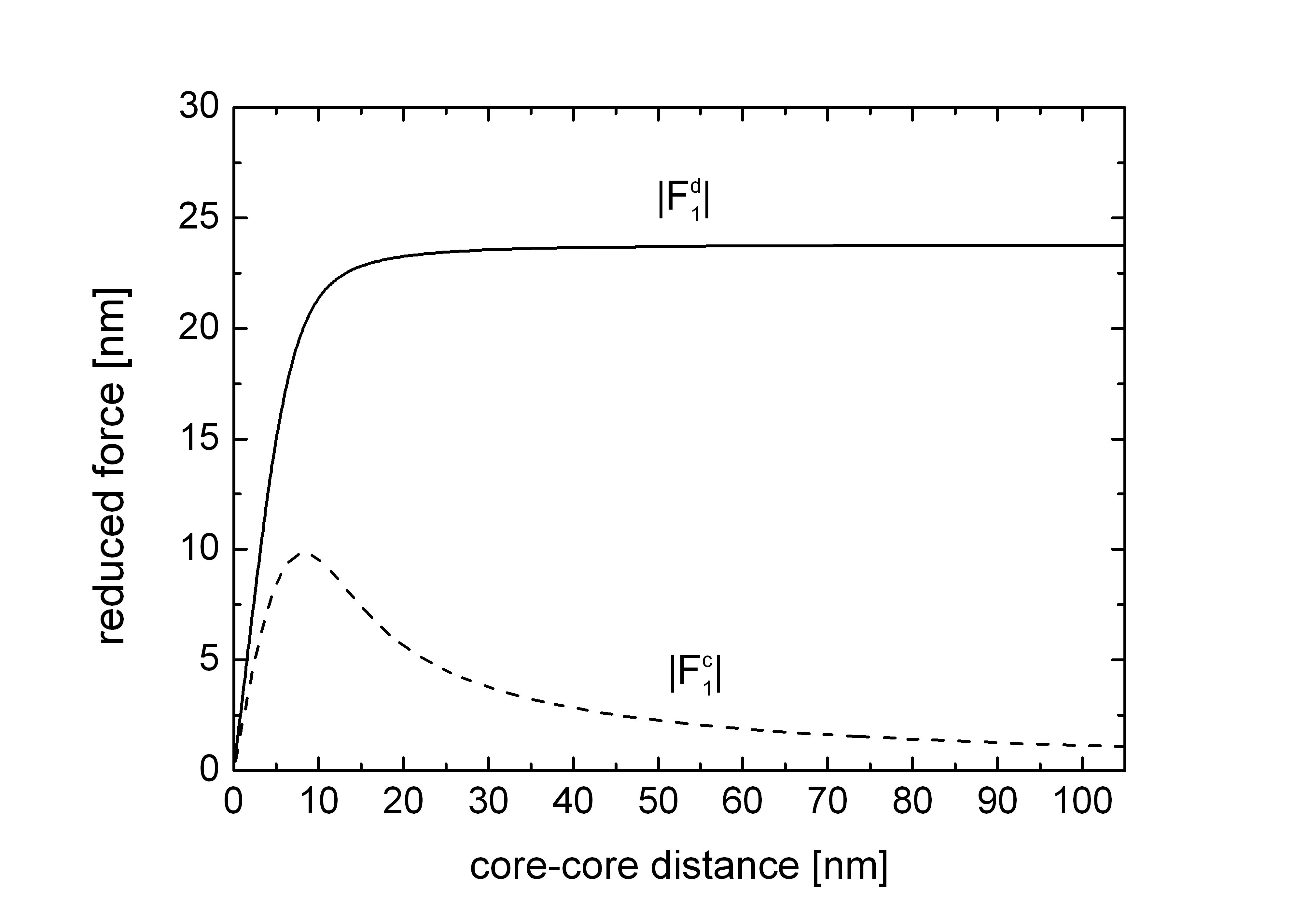
is the gyro vector, where and are the disk thickness and the vortex core polarity, respectively. is the core position with respect to the disk center, refers to the effective magnetostatic potential in which the core is moving, and characterizes the damping of the vortex motion. The parameters and are the radii of the disk and the vortex core, and the indices 1 and 2 correspond to the top and bottom disks, respectively. The spin-transfer torque-induced force acting on the vortex generated by a vortex-polarizer can be decomposed into two contributions . arises from the in-plane magnetization of the polarizer and acts on the core of the free vortex. The second term is caused by the core of the polarizer-vortex and acts on the in-plane magnetization of the free vortex. Both force contributions depend on the lateral core-core distance . Following Ref. Iva2007 , we obtain the expressions
| (2) | |||||
and
| (3) |
where we introduce the vectors
| (4) |
defines the vorticity (“+” corresponds to counterclockwise, “-” to clockwise) and refers to the th component of the bottom vortex unit magnetization vector. The top layer magnetization is written in spherical coordinates , where and are the azimuthal and polar angles, respectively. In the calculation we assume rigid vortices with thickness-independent magnetization. The cylinder axis is chosen as the -axis. Using the ansatz of Feldtkeller and Thomas Fel1965 for the out-of-plane core magnetization ( with to mimic the experimentally obtained vortex core size in Fe Wac2002 ), we obtain the forces and their dependence on the lateral core-core distance as shown in Fig. 1. For large , the contribution of to the total force becomes negligible. This explains the simulation results reported in Ref. Khv2010 , where the influence of the polarizer-vortex core on the dynamics was found to be small. From Eq. (3) we see that this is caused by the reduction of the function with increasing distance from the top vortex core. In contrast to the asymptotic decrease of to zero, the magnitude of approaches a finite value for large . For small distances , however, we observe that both torques fall to zero. This can be attributed to the gain in symmetry with decreasing core-core distance. The small torque introduced by is neglected in our investigation on the dynamics of the system with the vortices coupled by the electric current. This is justified by the fact that we are interested in the general behavior of the solutions. The decrease of at small must however be included. The coupled Thiele equations read, with
| (5) | |||
| (6) |
The sign of is positive for electron
flow from the top to the bottom layer.
For a quantitative analysis of the solutions, we use parabolic approximations to the effective magnetostatic potentials. We let , resulting in a top vortex eigenfrequency of .
The bottom disk potential is fixed at (). These frequencies
are chosen to represent our Fe/Ag/Fe nanopillars with ferromagnetic
layers with a thickness ratio of 5/3.
We use a current of corresponding to about (for ), which is within the range of experiments. The spin-transfer torque-induced force is assumed to increase linearly from to , from whereon it is set to the constant value .
The solutions are obtained numerically using Maple’s rkf45 implementation Map2011 .
The results can be summarized as follows: For
positive currents and equal vorticities, the top vortex gyrates around the disk center on a trajectory of about in radius, regardless of the core polarity. The sense of rotation
is determined by the core polarization (counterclockwise for
positive and clockwise for negative core polarity). The gyration
frequency is . The
bottom vortex adapts its frequency and sense of gyration according to the top
vortex. A dynamic equilibrium develops with a constant phase
difference between the vortices even in the case of opposite relative
core orientation. This frequency adaption is accompanied by a strong
reduction in radius of the bottom core trajectory: for parallel
cores, the radius is about while for the
antiparallel configuration, the reduction is even more pronounced
(approximately ). For negative currents, the vortices
switch roles: The bottom vortex gyrates on a large orbit
(), while the top vortex trajectory is quenched
( for parallel, for antiparallel
core alignment). In the dynamic equilibrium the phase difference is
constant and the gyration frequency is about . This
frequency corresponds to the eigenfrequency of the bottom vortex while
the sense of rotation is determined by its core polarity.
The gyration phase difference between the
two vortices depends on the relative core alignment. For
positive currents and parallel cores, the bottom core gyrates
approximately ahead of its top counterpart, while
for antiparallel cores a lag is observed.
From Eqs. (5) and (6) it is clear that the solutions for opposite
vorticities are identical to those obtained for equal vorticities with
a negative current polarity.
For large enough , the obtained characteristics
of the dynamics are the generalization of the criterion found in
Ref. Khv2010 . In the model used by those authors, the polarizer was assumed to be
a fixed, rigid vortex, and only magnetization dynamics in the other, free
disk was allowed. In our case, both disks can be polarizing or free
layer. For a given combination of vorticities and
applied current polarity, the system responds with a damped and a
dominant gyration, the former defining the polarizing and the latter
the free disk. The current polarity determines which disk is
dominantly excited. Therefore, the generalized -criterion reads:
For the top and for the bottom disk is
excited.
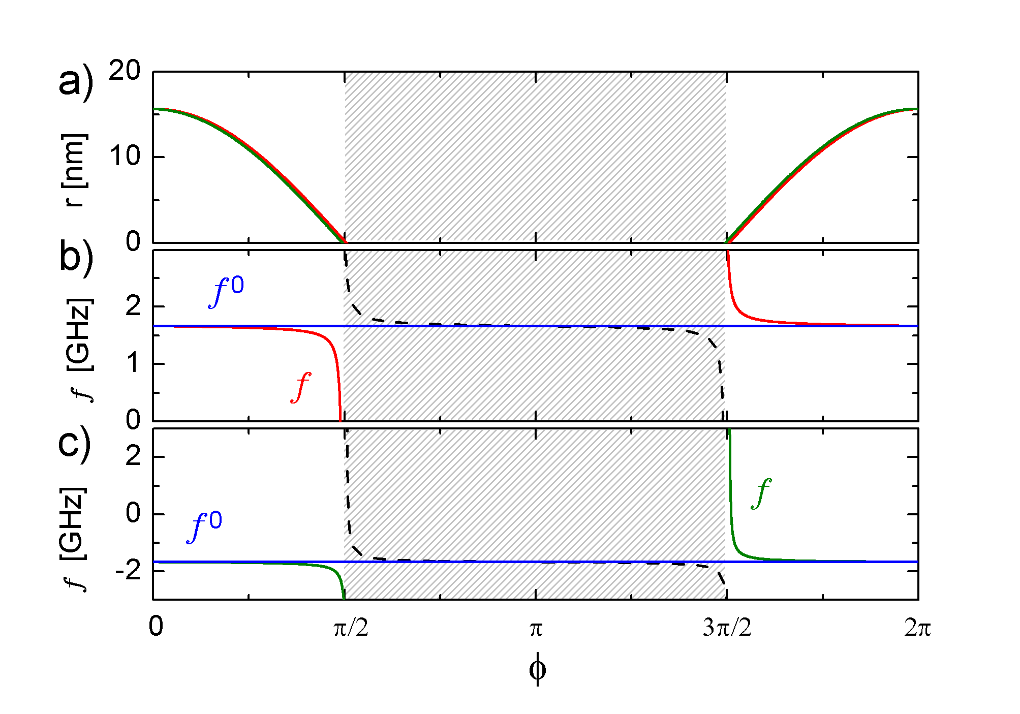
A general analytical solution for steady state trajectories is difficult to establish due to the complexity of the denominator in Eq. (4); however, it is instructive to analyze the situation when one trajectory radius is much larger than the other, a condition that, according to our numerical results, also holds in the vicinity of the limit cycle. We consider the case of positive and replace the denominator in Eq. (4) by , yielding the following relations between the radius of the bottom vortex trajectory, its phase (relative to the top vortex) and the common frequency of the two oscillators:
| (7) |
| (8) |
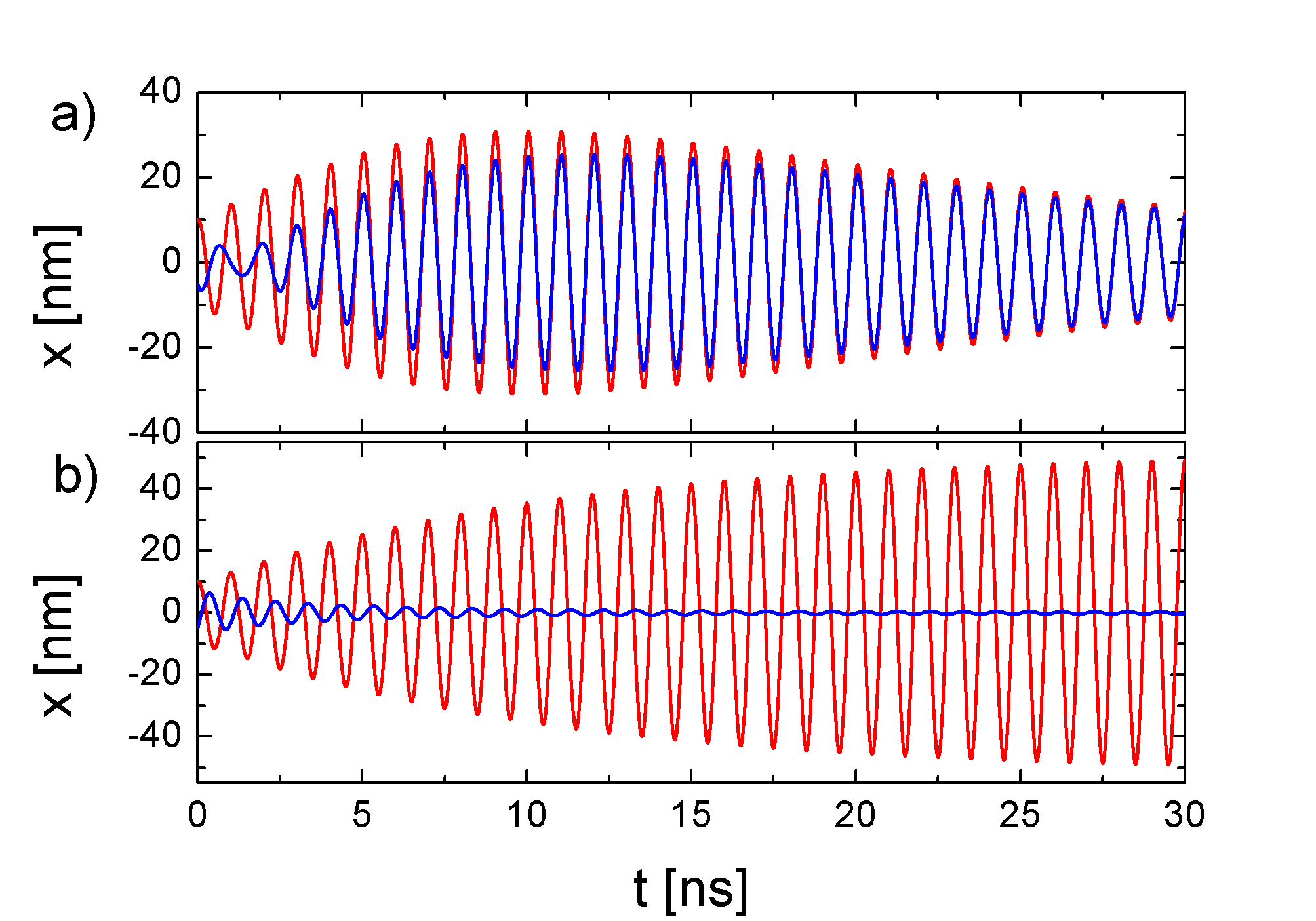
These relations are displayed in Fig. 2 and reproduce the behavior observed in the numerical solutions: For both cases of positive and negative bottom vortex core polarity, the bottom vortex can adapt to the (a priori arbitrary) frequency of the top vortex by adjusting the phase. Positive (negative) frequency corresponds to counterclockwise (clockwise) gyration. As displayed in Fig. 2(a), this phase shifting comes with a strong reduction of the orbit radius- or, in other words, a quenching of the windmill-modes. The dashed lines in the shaded regimes correspond to solutions of negative radius. Since a reverse of the sign of the radius is equivalent to a phase shift of , these negative- solutions are identical to the trajectories represented by the solid lines. By means of a phase adaption and reduction of the radius, the vortex can use a fraction of the spin-transfer torque-induced force to assist or counteract the force due to its magnetostatic potential. The resulting radial force component can differ strongly from the purely magnetostatic force. It may even lead to an inversion of the relation between the sense of gyration and the core polarity. A special case is the configuration, for which a frequency adaption is not necessary, i.e., if the two disks are identical and the cores parallel [Fig. 3a)].
In this case, the vortices start rotating in phase, but as they reach the limit cycle and the core-core distance drops below , the mutual spin-transfer torque-induced force decreases leading to a decay of the oscillation amplitudes.
For antiparallel alignment, the windmill-modes are quenched by the mechanism of frequency and phase adaption [Fig. 3b].
For an experimental confirmation of the frequency
and phase adaption mechanism and the related quenching of the windmill
modes we study the current-induced magnetization dynamics of an
Fe/Ag/Fe nanopillar with a Fe layer thickness ratio of 5/3. According
to our model, we expect to observe excitations for both current
polarities, but with different frequencies yielding a frequency ratio
of approximately 5/3. Cylindrical nanopillars are patterned using
e-beam lithography and Ar ion milling from molecular beam
epitaxy-grown GaAs(001)/ Fe(1)/Ag(150)/Fe(25)/Ag(6)/Fe(15)/Au(25)
stacks (layer thicknesses in nm). The pillar diameter is
. The milling was stopped after reaching the
thick Ag buffer layer. Thus, the oscillator
consists of two ferromagnetic disks of equal diameter and comparable
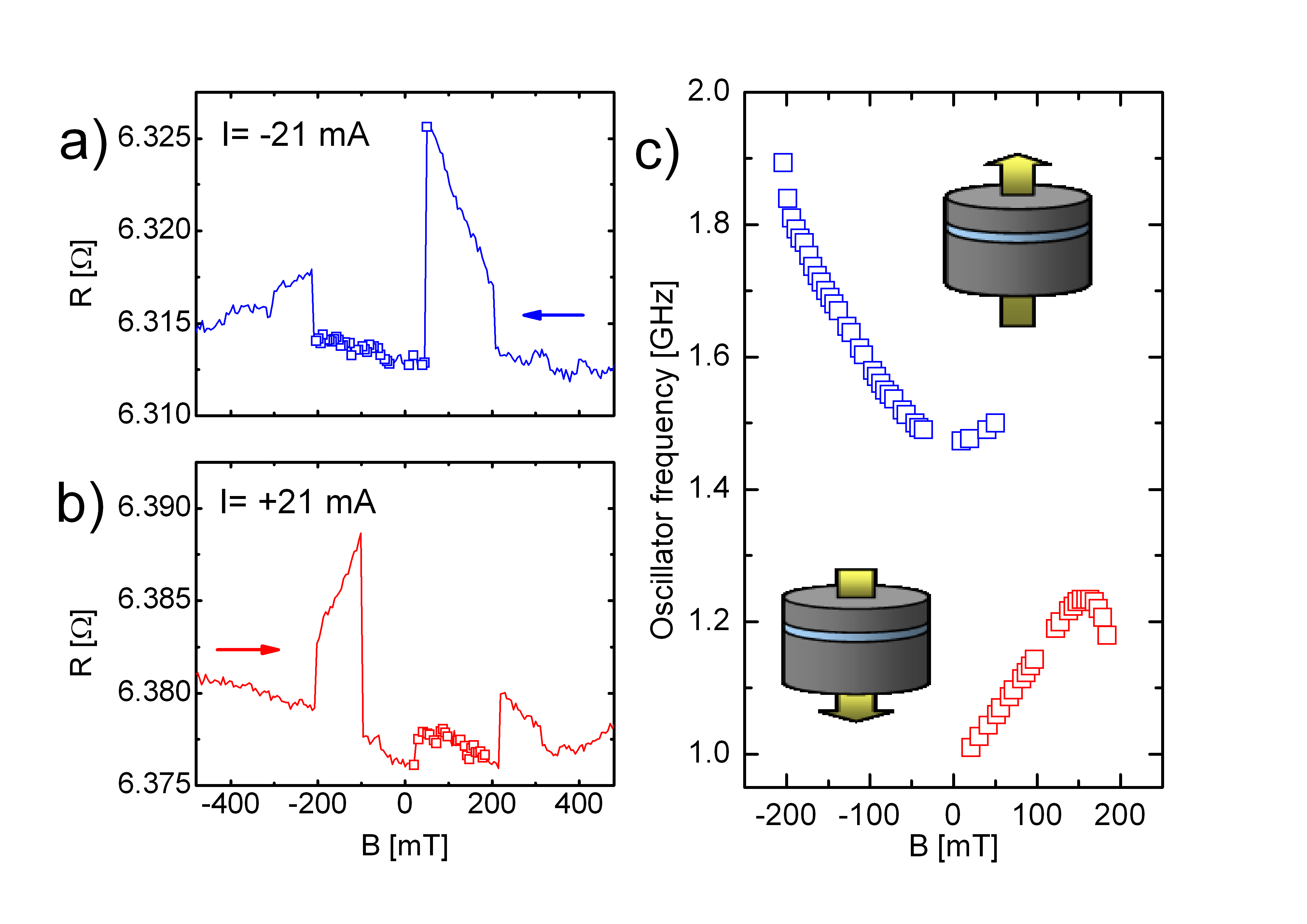
thickness stacked on top of each other. Figures 4(a) and (b)
display the field dependence of the nanopillar resistance for
mA ( A/cm2), respectively. The
external magnetic field was applied in the sample plane. The
magnetoresistance profiles are characteristic for this sample type
Slu2011
and reflect two magnetization states: The first
one comprises a vortex in one disk, while the other nanomagnet remains
in a quasi-homogeneous state. These configurations are characterized
by a nearly linear field dependence of the resistance caused by a
continuous lateral displacement of the vortex with changing field.
The second state is observed from low field magnitudes up to about
and is characterized by low resistance values near
the level in magnetic saturation. Here, each disk contains a vortex with
the vorticity given by the circumferential Oersted field. This
results in locally parallel alignment of the two disks’ magnetizations
explaining the observed low resistance. For both current polarities
in Figs. 4(a) and (b) we detected magnetization dynamics in
those field intervals, in which the double-vortex state occurs. The
excitation frequencies are shown in Fig. 4(c) along with the
corresponding electron flow directions of the externally applied
currents . All frequencies are below , which is
typical for vortex gyration in Fe/Ag/Fe nanopillars
Leh2009 ; Leh2010 ; Slu2011 , but the
frequencies are clearly different and well separated for the two
current polarities. At low external fields their ratio is about
. Using previous data on single vortex dynamics
Khv2009 ; Slu2011 , we estimate the influence of the Oersted field
on the zero-field vortex frequencies to be MHz for both disks. This shifts the above value to , i.e. very close to the ratio of the disk aspect ratios ().
Since the gyration frequency of a vortex in a ferromagnetic disk is in a first approximation proportional to the disk aspect ratio Gus2002 , our data strongly suggests that, as proposed, the
observed signals at opposite current polarities originate from
excitations in the two different disks, the low(high)-frequency mode
corresponding to gyrotropic motion of the vortex in the top (bottom)
disk. The dominantly excited disk is determined by current polarity in
agreement with our model.
In summary, we have theoretically and experimentally
demonstrated that windmill modes are quenched in double-vortex
spin-torque nano-oscillators. The origin is frequency and phase
adaption of the gyrotropic motions in the two disks, which results in a
strong suppression of the gyration radius in one of the disks.
Changing the sign of the exciting current provides an effective mode
selection mechanism, which allows to deliberately choose between
separated frequency bands of the oscillator.
We would like to thank C. Fowley for helpful discussions. A. M. D. acknowledges financial support from the EU project STraDy (MOIF-CT-2006-039772) and Swiss National Science Foundation Ambizione grant PZ00P2_131808.
References
- (1) S. A. Wolf et al., Science 294, 1488 (2001).
- (2) S. I. Kiselev et al., Nature 425, 380 (2003).
- (3) I. N. Krivorotov et al., Science 307, 228 (2005).
- (4) F. B. Mancoff, N. D. Rizzo, B. N. Engel, and S. Tehrani, Nature 437, 393 (2005).
- (5) S. Kaka et al., Nature 437, 389 (2005).
- (6) T. J. Silva and W. H. Rippard, J. Magn. Magn. Mater. 320, 1260 (2007).
- (7) A. M. Deac et al., Nature Phys. 4, 803 (2008).
- (8) J. C. Slonczewski, J. Magn. Magn. Mater. 159, L1 (1996).
- (9) L. Berger, Phys. Rev. B 54, 9353 (1996).
- (10) J. C. Slonczewski, J. Magn. Magn. Mater. 247, 324 (2002).
- (11) Y. B. Bazaliy, D. Olaosebikan, and B. A. Jones, J. Nanosci. Nanotechnol. 8, 2891 (2008).
- (12) M. Tsoi, J. Z. Sun, and S. S. P. Parkin, Phys. Rev. Lett. 93, 036602 (2004).
- (13) A. A. Thiele, Phys. Rev. Lett. 30, 230 (1973).
- (14) B. A. Ivanov and C. E. Zaspel, Phys. Rev. Lett 99, 247208 99, 247208 (2007).
- (15) A. V. Khvalkovskiy et al., Appl. Phys. Lett. 96, 212507 (2010).
- (16) E. Feldtkeller and H. Thomas, Phys. kondens. Mat. 4, 8 (1965).
- (17) A. Wachowiak et al., Science 298, 577 (2002).
- (18) http://www.maplesoft.com/.
- (19) V. Sluka et al., J. Phys. D: Appl. Phys. 44, 384002 (2011).
- (20) R. Lehndorff et al., Phys. Rev. B 80, 054412 (2009).
- (21) R. Lehndorff, D. E. Bürgler, C. M. Schneider, and Z. Celinski, Appl. Phys. Lett. 97, 142503 (2010).
- (22) A. V. Khvalkovskiy, J. Grollier, A. Dussaux, K. A. Zvezdin and V. Cros, Phys. Rev. B 80, 140401(R) (2009).
- (23) K. Y. Guslienko et al., J. Appl. Phys. 91, 8037 (2002).