Experimental observation of the spin Hall effect of light on a nano-metal film via weak measurements
Abstract
We theorize the spin Hall effect of light (SHEL) on a nano-metal film and demonstrate it experimentally via weak measurements. A general propagation model to describe the relationship between the spin-orbit coupling and the thickness of the metal film is established. It is revealed that the spin-orbit coupling in the SHEL can be effectively modulated by adjusting the thickness of the metal film, and the transverse displacement is sensitive to the thickness of metal film in certain range for horizontal polarization light. Importantly, a large negative transverse shift can be observed as a consequence of the combined contribution of the ratio and the phase difference of Fresnel coefficients.
pacs:
42.25.-p, 42.79.-e, 41.20.JbI Introduction
The spin Hall effect of light (SHEL) manifests itself as the split of a linearly polarized beam into left- and right-circular components when a beam propagates through homogeneous media. The splitting in the SHEL, governed by the angular momentum conservation law Onoda2004 ; Bliokh2006 , takes place as a result of an effective spin-orbit coupling. The SHEL is sometimes referred to as the Imbert-Fedorov effect, which was theoretically predicted by Fedorov and experimentally confirmed by Imbert Fedorov1965 ; Imbert1972 . Generally the transverse shift of the SHEL is on the subwavelength scale, and it is difficult to be directly measured with the conventional experimental methods. In 2008, benefiting from the weak measurement technique, Hosten and Kwiat first measured the transverse displacement of refracted light Hosten2008 . The SHEL has been widely investigated in different physical systems, such as high-energy physics Gosselin2007 ; Dartora2011 , plasmonics Gorodetski2008 ; 2Bliokh2008 ; Vuong2010 , optical physics Bliokh2008 ; Aiello2008 ; Haefner2009 ; Herrera2010 ; Qin2009 ; Luo2009 , and semiconductor physics Menard2010 ; Menard2009 .
The SHEL holds great potential applications, such as manipulating electron spin states and precision metrology Hosten2008 . The SHEL itself may become a useful metrological tool for characterizing the refractive index variations of nanostructure. Thus, the relationship between SHEL and nanostructure is important, yet it is not fully understood. To measure the refractive index variations at subwavelength scale, we need to establish the relationship between the SHEL and the structural parameters of the nanostructure. It is well known that the SHEL manifests itself as the spin-orbit coupling. Now a question arises: What role does the structural parameters of the subwavelength nanostructure play in the spin-orbit coupling?
In this work, we establish a general propagation model to describe the SHEL on the nano-metal film and reveal the impact of the structural parameters on the SHEL. We find that the spin-orbit coupling in the SHEL can be effectively modulated by adjusting the thickness of the metal film. It should be noted that the interesting SHEL on this structure is different from that on pure glass prism Hosten2008 ; Qin2009 , metal bulk Hermosa2011 , and layered nanostructure 2Luo2011 . The paper is organized as follows. First, we analyze the SHEL on the nano-metal film theoretically. Our findings indicate that the transverse displacement of the SHEL is sensitive to the thickness of the metal film and undergoes a large negative value for horizontal polarization. Next, we focus our attention on the experiment (weak measurements). Here, the sample is a BK7 substrate coated with a thin Ag film. The experimental results are in good agreement with the theory. Finally, a conclusion is given in the fourth section.
II Theoretical model
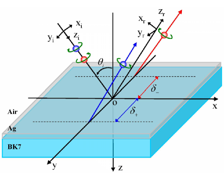
Figure 1 schematically illustrates the SHEL of beam reflection on a nano-metal film in Cartesian coordinate system. The axis of the laboratory Cartesian frame () is normal to the interface of the metal film at . The incident and reflected electric fields are presented in coordinate frames () and (), respectively. In the spin basis set, the angular spectrum can be written as and . Here, and represent horizontal and vertical polarizations, respectively. The positive and negative signs denote the left- and right-circularly polarized (spin) components, respectively.
The incident monochromatic Gaussian beam can be formulated as a localized wave packet whose spectrum is arbitrarily narrow, and can be written as
| (1) |
where is the beam waist. The polarization operator corresponds to left- and right-circularly polarized light, respectively. According to the transversality, we can obtain the reflected field 2Luo2011
| (8) |
Here, and denote Fresnel reflection coefficients for parallel and perpendicular polarizations, respectively. is the wave number in free space.
From Eqs. (1) and (8), we can obtain the expressions of the reflected angular spectrum
| (9) |
| (10) |
Here, , , and can be written as
| (11) |
It is known that the spin-orbit coupling is the intrinsic physical mechanism of the SHEL. We note that, in Eqs. (9) and (10), the terms and the indicate the spin-orbit coupling terms in the case of horizontal and vertical polarizations Hosten2008 . The spin-orbit coupling terms stem from the transverse nature of the photon polarization: The polarizations associated with the plane-wave components undergo different rotations in order to satisfy the transversality after reflection Hosten2008 . We can find that increasing or decreasing term will significantly enhance or suppress the spin-orbit coupling effect.
It is noted that the real parts of the spin-orbit coupling terms denote the spatial shift of the SHEL Aiello2009 . Hence, we can obtain the initial transverse displacement of the SHEL on the nano-metal film:
| (12) |
| (13) |
where and is wavelength of the incident beam. Calculating the reflected shifts of the SHEL requires the explicit solution of the boundary conditions at the interfaces. Thus, we need to know the generalized Fresnel reflection of the metal film,
| (14) |
Here, , and is the Fresnel reflection coefficients at the first interface and second interface, respectively. and represent the permittivity and thickness of the metal film, respectively.
To obtain a clear physical picture, we plot Fig. 2 to reveal what role the thickness of the nano-meta film plays in the spin-orbital coupling. Figure 2(a) and 2(b) show the initial transverse shifts of the SHEL with different film thickness. In the case of horizontal polarization, we find that the transverse displacement is extremely sensitive to the thickness when it is less than about . We find that this interesting phenomenon is attributed to the large variations of [Fig. 2(c)]. However, as for vertical polarizations, the transverse shift is insensitive to the thickness because of small variations of [Fig. 2(d)]. It should be noted that, from Eqs. (9) and (12), the term of plays a dominant role in spin-orbit coupling. Hence, we can enhance or suppress the SHEL effectively by modulating the thickness of the metal film. Similar effect can also be observed in a layered nanostructures, in which the transverse displacement changes periodically with the air gap increasing or decreasing due to the optical Fabry-Perot resonance 2Luo2011 .
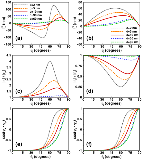
In the case of horizontal polarization, the transverse shift experiences large negative value [Fig. 2(a)], which is different from the SHEL on a metal bulk Hermosa2011 . From Eqs. (12) and (13), we can find that, for a fixed incident angle, negative shifts entail the combined contributions of the large ratio of Fresnel coefficients ( or ) and phase difference induced negative or [Fig. 2(e) and 2(f)] which are due to the material properties of the metal film. We conclude that large negative transverse displacement only exists in the case of horizontal polarization while always is positive under the condition of vertical polarizations. It is indicated that by rotating the polarization of incident light beam, we are able to switch the direction of the spin accumulation Luo2011 effectively. Similar phenomena also occur in electronic system. Here, the spin accumulation can be switched by altering the directions of an external magnetic field Sinova2004 ; Kimura2007 ; Mihaly2008 . By rotating the polarization plane of the exciting light, the directions of spin current can be switched in a semiconductor microcavity due to the spin Hall effect Kavokin2005 ; Leyder2007 .
III Experimental observation
To detect the tiny transverse shifts, we use the signal enhancement technique known as the weak measurements Aharonov1988 ; Ritchie1991 . Note that the weak measurements has attracted a lot of attention and holds great promise for precision metrology Pryde2005 ; Dixon2009 ; Brunner2010 ; Kocsis2011 ; Feizpour2011 ; Zilberberg2011 . The theoretical analysis of the SHEL on nano-metal film has yielded two major results: sensitive SHEL in extremely thin metal film and large negative beam shift of horizontal polarized incident beam. However, we inevitably face a major obstacle that prevents us from experimentally corroborating the first claim because fabricating Ag film thinner than would unavoidably involve large technical errors. Nonetheless, we still attempt to verify the validity of our theory by measuring the SHEL in large film thickness. In this section, we choose the BK7 glass substrate coated Ag film as our sample (with three different thickness , and .
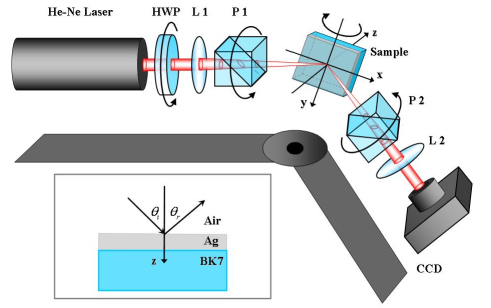
Our experimental setup shown in Fig. 3 is similar to that in Refs Hosten2008 ; Qin2009 . A Gauss beam generated by a He-Ne laser firstly impinges onto the HWP which is used to control the light intensity to prevent the charge-coupled device (CCD) from saturation. And then, the light beam passes through a short focal length lens (L1) and a polarizer (P1) to produce an initially linearly polarized focused beam. When the beam reaches the sample interface, the SHEL takes place. The sample is a BK7 glass substrate coated with a thin Ag film whose permittivity is at Palik1998 . As the reflected beam splits by a fraction of the wavelength, the two components interfere destructively after the second polarizer (P2), which is oblique to P1 with an angle of . In our weak measurements experiment, we choose the angle . Then we use L2 to collimate the beam and make the beam shifts insensitive to the distance between L2 and the CCD. Finally, we use a CCD to measure the amplified shift after L2. It should be mentioned that the amplified factor is not a constant, which verifies the similar result of our previous work Luo2011 .
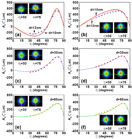
We measure the displacements of the SHEL on the nano-metal film every from to in the case of horizontal and vertical polarization, respectively. Limited by the large holders of the lens, polarizers and He-Ne laser, displacements at small incident angles were not measured. Figure 4 plots the amplified displacement in both theoretically and experimentally. In the case of horizontal polarization, the shift first experiences a negative value and then increases with the incident angle. After reaching the peak value in the incident angle about , the shift decreases rapidly. For three different thicknesses, the negative shifts are vary. With the thickness increasing, the range of negative shift decreases. In the case of vertical polarization, the shift first increases with the incident angle and also decreases rapidly after the peak value. But, there exists no negative values compared with the horizontal polarization.
It should be noted that the experimental results are in good agreement with the theoretical ones when the film thicknesses are and [Fig. 4(c)-(f)]. However, we observe a small deviation when the thickness is [Fig. 4(a) and 4(b)]. Note that the thickness of the nano-meta film has an error in the range of , limited by the experimental condition. When the thickness reaches to , the SHEL is very sensitive to the error. It is the reason why there is a small deviation between the experimental and the theoretical data. From the experimental results, we can conclude that the actual thickness of the film is about . This interesting characteristic may provide a potential way for measuring the thickness of the nano-metal film.
IV Conclusions
In conclusion, we have observed the SHEL on a nano-metal film experimentally via weak measurements. We have found that the spin-orbit coupling effect can be effectively manipulated by adjusting the thickness of the metal film. Our findings indicate that the transverse displacement is sensitive to the thickness of the metal film in certain range. Hence, altering the metal film thickness will enhance or suppress the SHEL significantly. As an analogy of spin Hall effect in an electronic system, we are able to switch the directions of the spin accumulation in SHEL effectively by rotating the polarization of incident light beam. These findings provide a pathway for modulating the SHEL and thereby open the possibility of developing nanophotonic applications.
Acknowledgements.
One of the authors (X. Z.) thanks Dr. Y. Qin and Dr. N. Hermosa for helpful discussions. We are sincerely grateful to the anonymous referee, whose comments have led to a significant improvement on our paper. This research was supported by the National Natural Science Foundation of China (Grants Nos. 61025024, 11074068).References
- (1) M. Onoda, S. Murakami, and N. Nagaosa, Phys. Rev. Lett. 93, 083901 (2004).
- (2) K. Y. Bliokh and Y. P. Bliokh, Phys. Rev. Lett. 96, 073903 (2006).
- (3) F. I. Fedorov, Dokl. Akad. Nauk SSSR 105, 465 (1955).
- (4) C. Imbert, Phys. Rev. D 5, 787 (1972).
- (5) O. Hosten and P. Kwiat, Science 319, 787 (2008).
- (6) P. Gosselin, A. Bérard, and H. Mohrbach, Phys. Rev. D 75, 084035 (2007).
- (7) C. A. Dartora, G. G. Cabrera, K. Z. Nobrega, V. F. Montagner, M. H. K. Matielli, F. K. R. de Campos, and H. T. S. Filho, Phys. Rev. A 83, 012110 (2011).
- (8) Y. Gorodetski, A. Niv, V. Kleiner, and E. Hasman, Phys. Rev. Lett. 101, 043903 (2008).
- (9) K. Y. Bliokh , Y. Gorodetski, V. Kleiner, and E. Hasman, Phys. Rev. Lett. 101, 030404 (2008).
- (10) L. T. Vuong, A. J. L. Adam, J. M. Brok, P. C. M. Planken, and H. P. Urbach, Phys. Rev. Lett. 104, 083903 (2010).
- (11) K. Y. Bliokh, A. Niv, V. Kleiner, and E. Hasman, Nature Photon. 2, 748 (2008).
- (12) A. Aiello and J. P. Woerdman, Opt. Lett. 33, 1437 (2008).
- (13) D. Haefner, S. Sukhov, and A. Dogariu, Phys. Rev. Lett. 102, 123903 (2009).
- (14) O. G. Rodríguez-Herrera, D. Lara, K. Y. Bliokh, E. A. Ostrovskaya, and C. Dainty, Phys. Rev. Lett. 104, 253601 (2010).
- (15) Y. Qin, Y. Li, H. He, and Q. Gong, Opt. Lett. 34, 2551 (2009).
- (16) H. Luo, S. Wen, W. Shu, Z. Tang, Y. Zou, and D. Fan, Phys. Rev. A 80, 043810 (2009).
- (17) J.-M. Ménard, A. E. Mattacchione, M. Betz, and H. M. van Driel, Opt. Lett. 34, 2312 (2009).
- (18) J.-M. Ménard, A. E. Mattacchione, H. M. van Driel, C. Hautmann, and M. Betz, Phys. Rev. B 82, 045303 (2010).
- (19) N. Hermosa, A. M. Nugrowati, A. Aiello and J. P. Woerdman, Opt. Lett. 36, 3200 (2011).
- (20) H. Luo, X. Ling, X Zhou, W. Shu, S. Wen, and D. Fan, Phys. Rev. A 84, 033801 (2011).
- (21) A. Aiello, M. Merano, and J. P. Woerdman, Phys. Rev. A 80, 061801 (2009).
- (22) H. Luo, X. Zhou, W. Shu, S. Wen, and D. Fan, Phys. Rev. A 84, 043806 (2011).
- (23) J. Sinova, D. Culcer, Q. Niu, N. A. Sinitsyn, T. Jungwirth, and A. H. MacDonald, Phys. Rev. Lett. 92, 126603 (2004).
- (24) T. Kimura, Y. Otani, T. Sato, S. Takahashi, and S. Maekawa, Phys. Rev. Lett. 98, 156601 (2007).
- (25) G. Mihály, M. Csontos, S. Bordács, I. Kézsmarki, T. Wojtowicz, X. Liu, B. Jankó, and J. K. Furdyna, Phys. Rev. Lett. 100, 107201 (2008).
- (26) A. Kavokin, G. Malpuech, and M. Glazov, Phys. Rev. Lett. 95, 136601 (2005).
- (27) C. Leyder, M. Romanelli, J. Ph. Karr, E. Giacobino, T. C. H. Liew, M. M. Glazov, A. V. Kavokin, G. Malpuech, and A. Bramati, Nature Phys. 3, 628 (2007).
- (28) Y. Aharonov, D. Z. Albert, and L. Vaidman, Phys. Rev. Lett. 60, 1351 (1988).
- (29) N. W. M. Ritchie, J. G. Story, and R. G. Hulet, Phys. Rev. Lett. 66, 1107 (1991).
- (30) G. J. Pryde, J. L. O’Brien, A. G. White, T. C. Ralph, and H. M. Wiseman, Phys. Rev. Lett. 94, 220405 (2005).
- (31) P. B. Dixon, D. J. Starling, A. N. Jordan, and J. C. Howell, Phys. Rev. Lett. 102, 173601 (2009).
- (32) N. Brunner, and C. Simon, Phys. Rev. Lett. 105, 010405 (2010).
- (33) S. Kocsis, B. Braverman, S. Ravets, M. J. Stevens, R. P. Mirin, L. K. Shalm, and A. M. Steinberg, Science 332, 1170 (2011).
- (34) A. Feizpour, X. X. Xing, and A. M. Steinberg, Phys. Rev. Lett. 107, 133603 (2011).
- (35) O. Zilberberg, A. Romito, and Y. Gefen, Phys. Rev. Lett. 106, 080405 (2011).
- (36) E. D. Palik, Handbook of Optical Constants of Solids (Academic, New York, 1998).