Conservation relations and anisotropic transmission resonances in one-dimensional -symmetric photonic heterostructures
Abstract
We analyze the optical properties of one-dimensional (1D) -symmetric structures of arbitrary complexity. These structures violate normal unitarity (photon flux conservation) but are shown to satisfy generalized unitarity relations, which relate the elements of the scattering matrix and lead to a conservation relation in terms of the transmittance and (left and right) reflectances. One implication of this relation is that there exist anisotropic transmission resonances in -symmetric systems, frequencies at which there is unit transmission and zero reflection, but only for waves incident from a single side. The spatial profile of these transmission resonances is symmetric, and they can occur even at -symmetry breaking points. The general conservation relations can be utilized as an experimental signature of the presence of -symmetry and of -symmetry breaking transitions. The uniqueness of -symmetry breaking transitions of the scattering matrix is briefly discussed by comparing to the corresponding non-Hermitian Hamiltonians.
pacs:
42.25.Bs, 42.25.Hz, 42.55.AhI Introduction
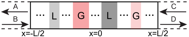
Motivated by fundamental studies of -symmetric quantum Hamiltonians Bender1 ; Bender2 ; Bender3 , -symmetric photonic structures have attracted considerable interest in the past few years. These are structures with balanced gain and loss; in the case of a one-dimensional (1D) structure, this means that there is a symmetry point (chosen to be the origin, ) around which the linear index of refraction satisfies . Such structures were first studied in Refs. El-Ganainy_optlett07 ; Makris_prl08 and were shown to exhibit a variety of exotic photon transport phenomena, such as double refraction Makris_prl08 , power oscillations Makris_prl08 ; ruter_natphy10 ; Zheng_pra10 , and non-monotonic behavior of the transmission loss with increased dissipation Guo_prl2009 . The initial studies focused on parallel waveguide structures with alternating loss and gain, in which the transverse variation of the electrical field, in the paraxial approximation to the wave equation, maps precisely onto a 1D or discrete Schrodinger equation, similar to the earlier quantum studies El-Ganainy_optlett07 ; Makris_prl08 ; ruter_natphy10 ; Zheng_pra10 ; Guo_prl2009 ; Musslimani_prl08 . The parallel waveguide realization of symmetric photonic structures has recently found a promising application to compact optical isolators and circulators Ramezani .
Recently, several authors have studied -symmetric cavities and heterostructures mostafazadeh ; Schomerus ; Longhi ; CPALaser , as well as general scattering systems CPALaser , using the full scalar wave equation, in the case that it obeys at least one symmetry operation. The current authors in particular emphasized the existence in such systems of -symmetric and -broken phases of the electromagnetic scattering matrix (S-matrix). For the 1D case, the eigenvalues of the S-matrix are unimodular in the -symmetric phase, as they are in unitary systems, but photon flux is not conserved for most scattering processes, whereas in the broken phase the S-matrix eigenvalues have reciprocal magnitudes, one greater than unity (corresponding to amplification), and the other less than unity (corresponding to attenuation). We and others Longhi ; Schomerus ; CPALaser ; mostafazadeh ; schomerus2 pointed out the existence of novel singular points in the broken symmetry phase, which we refer to as CPA-laser points. At these points one of the S-matrix eigenvalues goes to infinity (the usual lasing threshold condition), while the other goes to zero. The latter phenomenon corresponds to coherent perfect absorption (CPA)CPA ; CPA_science , in which a specific mode of the electromagnetic field, the time-reversal of the lasing mode, is completely absorbed. For -symmetric structures, these two phenomena must coincide Longhi ; CPALaser ; i.e. at the laser threshold, in addition to a radiating mode of self-oscillation, there always exists an incident field pattern which, instead of being amplified, is completely attenuated.
The rich behavior of 1D -symmetric photonic structures violates the standard intuition that optical structures can be characterized by their single-pass gain or loss, which is always zero in these systems. The coincidence of both lasing and perfect absorption, and more generally the reciprocal amplification and attenuation displayed by the S-matrix eigenvalues, is a strict consequence of the symmetry property of the S-matrix for such structures. In Ref. CPALaser this was expressed in arbitrary dimensions by the relation
| (1) |
where is the parity operator (or indeed any discrete symmetry operator with ), and is the time-reversal operator (in the representation we will employ, this can be taken as the complex conjugation operator). By comparison, a -symmetric unitary S-matrix would obey .
The set of S-matrices obeying Eq. (1) can be shown to be isomorphic to a pseudo-unitary group, which in the 1D case is just Mostafazadeh2 . In physical dimensions higher than one, there can be more than two input and output channels, and it is possible for the S-matrix to be in a mixed “phase” with one subset of the eigenvalues forming “-broken” amplifying/attenuating pairs and the remaining eigenvalues being “-symmetric” and flux conserving. For 1D structures, however, there are only two eigenvalues, and they must either be both unimodular, or a non-unimodular inverse conjugate pair—except at the -transition point, an exceptional point at which the S-matrix has only one eigenvector and eigenvalue CPALaser .
Several specific cases of 1D -symmetric structures have been studied mostafazadeh ; Longhi ; CPALaser ; invisibility and in addition to the interesting CPA-laser behavior, other intriguing properties have been found, such as unidirectional invisibility invisibility . It is thus worthwhile to see what specific properties -symmetry imposes on transmission and reflection in arbitrary structures, in both the symmetric and broken-symmetry phases. That is the goal of the current work. In Section II, we show that 1D structures obey certain strong conservation relations, which could be employed experimentally to determine if a given structure has realized symmetry. In Section III, we examine a consequence of these conservation relations: the existence of transmission resonances in which the reflectance vanishes only for waves incident from one side of the structure, which we refer to as anisotropic transmission resonances (ATRs). The uni-directional invisibility phenomenon found by Lin et al. invisibility is a special case of these ATRs. In Section IV, we derive a separate relation for the boundary between the -symmetric and -broken phases of the S-matrix, involving the reflectance and transmittance for one-sided scattering processes. In Section V, we show that our conventional definition of the S-matrix and its eigenvalues is physically meaningful, and in particular that its phase boundary can be related to -breaking transitions in the spectrum of some -symmetric Hamiltonian.
II Generalized Unitarity Relations
We begin, following Longhi Longhi , with the 1D transfer matrix , defined by (see Fig. 1):
| (2) |
For a -symmetric heterostructure, the components of obey the following properties Longhi :
| (3) |
where is the frequency of the incident/scattered beams. For real , these relations imply and , which enables us to parameterize as
| (4) |
It is determined by three independent real quantities, i.e. and the phase and amplitude of . The parameter is related to by
| (5) |
which arises from the quite general condition Yeh . The parametrization using is valid except when ; in that case, and replaces as the third independent parameter.
In the following discussion we assume non-vanishing and , which holds everywhere except at CPA-laser points bibnote0 . The S-matrix is defined by
| (6) |
where are the reflection coefficients for light incident from the left and right respectively, while is the transmission coefficient, which is independent of the direction of incidence. The parametrization (4) gives
| (7) |
Thus the reflection coefficients are and , which are unequal in magnitude but can differ in phase by only 0 or ; and the transmission coefficient is . Note that satisfies the symmetry relation (1), with and the complex conjugation operator. Using (5), we obtain the following exact “generalized unitarity relation”:
| (8) |
This leads to the conservation relation
| (9) |
where are the two reflectances and is the transmittance. In addition, Eqs. (7,8) lead to phase relationships among the reflection and transmission coefficients:
| (10) |
where are the phases of the reflection and transmission coefficients.
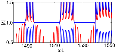
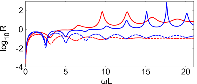
Eqs. (8,9) are the central results of this work. They are valid for all 1D photonic heterostructures with -symmetry; two examples are shown in Fig. 2.
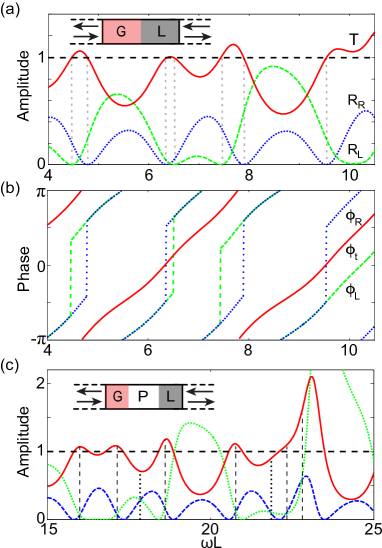
For , Eq. (9) becomes . This is an intriguing generalization of the more familiar conservation relation , which applies to unitary (-symmetric) S-matrices for which the left and right reflectances are necessarily equal. In the -symmetric case, the geometric mean of the two reflectances, , replaces the single reflectance . Therefore, when , the scattering of a single incident wave from one side of the structure is sub-unitary (some flux is lost) and the scattering from the other side is super-unitary (some flux is gained). As an exception, there can be an accidental degeneracy at which , in which case the scattering from both sides conserves flux. Such special cases do occur as a continuous parameter such as frequency is varied for non-trival systems (), as shown in Fig. 2(c).
For , all single-sided scattering processes are super-unitary, and the conservation relation (9) can be re-written as . Accidental reflectance degeneracies () are also possible in this regime, giving the usual pseudo-unitary conservation relation , as shown in Fig. 2(c). All of these quantities actually diverge when approaching the CPA-laser points, but they still satisfying the conservation relation (9).
Finally, we see that for , one of the reflectances must vanish (the other typically does not). Hence, the scattering for that direction of incidence is flux conserving, similar to resonant transmission in unitary structures. This phenomenon is analyzed in greater detail in Section III.
Interestingly, the S-matrix describing three-wave mixing in the undepleted pump approximation corresponds to the the special case where Longhi2 ; Stone_unpub . The case describes frequency conversion by absorption or emission of a pump photon, and describes parametric amplification of both signal and idler by down conversion of pump photons. The relevance of a special case of symmetry to optical parametric amplification and conversion has only very recently been appreciated.
An experimental concern in all systems is how to confirm that one has truly realized a structure with -symmetry, i.e. that the gain and loss are balanced and the real index is symmetric. Eqs. (8-10) are strong constraints on the allowed scattering processes with a single incident beam for systems, and can be used to test how close one is to the ideal symmetric structure.
III Anisotropic Flux-Conserving Transmission Resonances
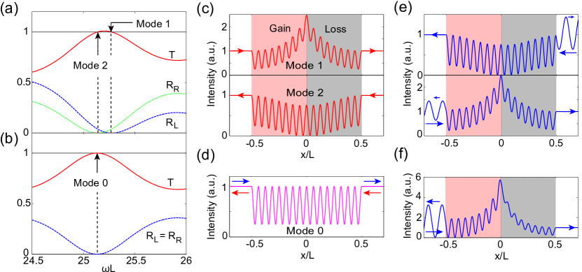
As we have noted, Eq. (9) implies an interesting phenomenon: there exists a flux-conserving scattering process for incident waves on a single side if and only if , and one of or vanishes. We refer to such a process as an anisotropic transmission resonance (ATR). ATRs are different from the accidental flux-conserving processes that can occur for ; those, as we have seen, are accessible from either direction of incidence (). ATRs are a generalization of the flux-conserving transmission resonances of unitary systems, which are independent of the incidence direction. In Fig. 3, we show how two ATRs evolve out of a single transmission resonance of the unitary system as balanced gain and loss is added. Within the same structure, ATRs can occur for both left and right incidence, as the frequency is varied, but generally at different frequencies (to occur at the same frequency, a “doubly accidental” degeneracy would have to occur, requiring a second tuning parameter).
A surprising property of ATRs is that their intensity profile is spatially symmetric. This can be shown from the following analysis. If is the spatial profile of a left-/right-going transmission resonance, then by a operation is also a left-/right-going transmission resonance of the same structure. Since these two states happen at the same frequency, they must be identical (up to a phase ) by the requirement of uniqueness:
| (11) |
Hence, the intensity satisfies . This result is consistent with the intuitive expectation that in order to conserve flux the photons must on average spend equal amount of time in the loss and gain regions of the structure. Except at the ATRs, intensities do exhibit asymmetry for single-sided incidence, and in particular this is the case for a wave incident from the side with non-vanishing reflectance; see Fig. 3(e),(f).
Fig. 3 shows two ATRs of a multi-layer structure, one for each incidence direction, occurring at different frequencies. The frequencies are very similar because is not very large and both ATRs arise from a bi-directional transmission resonance of the unitary () heterostructure. As we add gain and loss to the unitary heterostructure, while preserving the -symmetry, the transmission resonances separate and their spatial profiles become more distinct. Fig. 3(e) shows the asymmetric intensity profiles for waves incident at the ATR frequency, but from the “wrong” side (the side with non-vanishing reflectance). The asymmetry increases as the two ATRs move further apart with increasing gain/loss, as shown in Fig. 3(f).
Let us refer to the left and right halves of a -symmetric heterostructure as . We can write the reflection and transmission coefficients coefficients for the whole structure (, , and ) in terms of the reflection and transmission coefficients for the and segments:
| (12) | |||||
| (13) | |||||
| (14) |
Here, . Note that if either or at some , corresponding to a transmission resonance of in right/left direction, the transmittance for the full structure will also be unity.
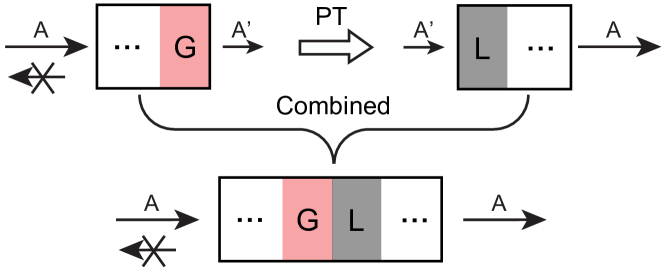
Thus one type of ATRs can arise from resonances of either half of the system. This follows from symmetry. First, using the time-reversal operation, a transmission resonance of from the left must be a transmission resonance of from the right (interchange gain and loss regions and interchange incoming and outgoing amplitudes)CPA_science . Second, the S-matrix of the right hand side of a structure is , so the right half of the structure must have a resonance for waves incident from the left side as well, if its left side does. Therefore the composite structure will have an ATR if either half does ( or ). This argument is illustrated graphically in Fig. 4; we refer to these as trivial ATRs.
ATRs also occur when or equals and involve multiple scattering between the sub-units. It is straightforward to check that at such points and . It can be shown that a single layer of gain or loss in a lossless environment (e.g. in air) does not have transmission resonances in general, and we show in the appendix that all the ATRs in Fig. 2 are of this type and are thus “non-trivial”.
As already noted, for an ATR to be bi-directional, a doubly accidental degeneracy is needed either in the amplitude of and () or their phase (). This is highly unlikely, unless one can tune an additional continuous parameter other than the frequency, so in the generic case all transmission resonances of structures are uni-directional.
In a recent work, Lin et al. invisibility have studied a 1D -symmetric Bragg structure of alternating dielectric layers with appropriate gain and loss, and discovered an ATR with an additional property which they refer to as “uni-directional invisibility”. Not only do they find (or vice versa), as dictated by Eq. (9); they also find that at this ATR the transmission phase , corresponding to zero phase delay of the signal compared to free propagation. For this reason there would be no signature of the presence of the structure in either amplitude or phase of the received wave, if the wave is sent from the correct side (there would be a signature of course in the reflected wave if sent from the wrong side). This condition, that at the ATR, is not required by our generalized unitarity relations and is specific to their structure bibnote:accidental_invisibility .
The existence of non-trivial ATRs is independent of whether the S-matrix is in the -symmetric or -broken phase CPALaser ; They can even occur at the symmetry-breaking exceptional point (see the following section). However, we do find for the simple gain-loss heterostructure of Fig. 2(a),(b) that the ATRs disappear soon after the lasing threshold is passed in the broken symmetry phase, since in the large limit approaches unity asymptotically. This is not the case for more complicated structures such as that of Fig. 2(c). The different behaviors of the two cases are illustrated in Fig. 10 of the Appendix and its origin is discussed.
IV Phase transition boundaries
A 1D -heterostructure can undergo a spontaneous symmetry-breaking transition in the eigenvalues and eigenvectors of its S-matrix, as either is increased at fixed gain/loss or as gain/loss is increased at fixed CPALaser . In the symmetric phase, the operation maps each scattering eigenstate back to itself, whereas in the broken symmetry phase each scattering eigenstate is mapped to the other. At the symmetry breaking exceptional point, there is only one eigenvector and so both cases coincide.
Let be the eigenvalues the S-matrix of a -symmetric heterostructure and be the ratios of the two amplitudes of the corresponding eigenstates. It follows from the S-matrix parameterization (7) that
| (15) | |||||
| (16) |
These equations imply that , and the eigenvalues must have reciprocal moduli. In the symmetric phase, both eigenvalues are unimodular, whereas the broken symmetry phase corresponds to the case. The exceptional point occurs when , and there is a single eigenvector with eigenvalue . Both the eigenvalues and amplitudes meet and bifurcate at the exceptional point, similar to the -breaking transitions which occur in the eigenvalue spectra of -symmetric Hamiltonians Bender1 ; Bender2 ; Bender3 ; El-Ganainy_optlett07 ; Makris_prl08 .
Each eigenvector of the S-matrix corresponds to a particular choice of two coherent beams, simultaneously directed at each side of the heterostructure. The S-matrix transition can in principle be observed by tuning the complex input amplitudes, measuring the output amplitudes, and hence finding the scattering eigenvalues. One would actually need to do such “two-sided” interference experiments to detect the attenuating mode in the broken symmetry phase, an interesting possibility which is currently being explored Stone_unpub . However, such experiments with two coherent input beams CPA_science are often inconvenient and difficult to perform. Therefore it would be preferable to have a criterion for the transition based on separate single-beam measurements.
In Ref. CPALaser two such criteria were given for the phase boundaries in an arbitrary -symmetric heterostructure; however they both involve the relative phase of the reflection and transmission coefficients. One of these conditions is . Using the conservation relations (9) this can be shown to lead to the simpler condition bibnote:altExp
| (17) |
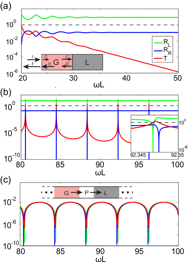
which involves only the transmittance and reflectances. The left hand side of Eq. (17) is greater than unity in the broken-symmetry phase and less than unity in the -symmetric phase. This provides a simple experimental criterion for locating the -breaking transition point in 1D heterostructures. This criterion will be particularly useful if the quantity varies rapidly near the transition point. This appears to be the case for many heterostructures, as shown for example in Fig. 5 for a three layer structure.
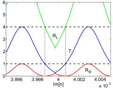
Eq. (17) implies that for an ATR to coincide with the exceptional point, the non-zero reflectance must be exactly equal to 4, which is allowed but will not occur without specific tuning. An example of such tuning is shown in Fig. 6. This plot is obtained by tuning both the gain/loss strength (Im) and the frequency, to keep the system along the phase boundary, and observing the reflectances and transmittance. Two ATRs are found along the phase boundary. We note that a special set of solutions of Eqs. (9) and (17) are given by , where is an arbitrary real number. Interestingly, the maxima of in this simple geometry are given by this set of solutions with in the high frequency regime where .
V Uniqueness of transition in scattering
The generalized unitarity relations (8)-(10) hold regardless of whether the eigenvalues and eigenvectors of the S-matrix are in the -symmetric or -broken phase; although the quantities in the generalized unitarity relations are related to the phase of the scattering system through the relation Eq. (17). There is, however, some freedom of choice in the definition of the 1D S-matrix, corresponding to permutation of the outgoing channels. The definition we used in Ref. CPALaser is given in Eq. (6), which is also widely used in mesoscopic physics Beenakker_rmp . In this section we will refer to the S-matrix defined in this way as . In the reflection coefficients are on the diagonal, and the outgoing channels are related to the corresponding incident channels by time reversal, which seems quite natural. In particular, the time-reversal operation in this definition is represented by the complex conjugation operator.
There is, however, an alternate definition:
| (18) |
which has also been used in the literature, including in one of the earliest works on -symmetric scattering, by Cannata et al. Cannata . This alternative definition of the S-matrix, which we will refer to as , was subsequently used in the work on unidirectional invisibility of Lin et al. invisibility . Because the permutation operation does not preserve the eigenvalues, these two different definitions of the S-matrix lead to different criteria for the symmetric and broken symmetry phases, as well as for the phase boundary (exceptional points). This can lead to confusion, as well as raising questions as to whether the S-matrix eigenvalues and eigenvectors, and their transitions, are physically meaningful.
Note first that both definitions lead to the same values for , so they will give the same scattered state for the same input state. The issue is whether one or the other definition more closely reflects the phenomena of spontaneous symmetry breaking, as already known from Hamiltonian studies. In our earlier work on the transition in scattering systems CPALaser , we showed that the phase boundary of corresponds closely to the anti-crossings of the poles of the S-matrix in the complex -plane (see also schomerus2 ). The locations of these poles are independent of the definition of ; they reflect the internal excitation frequencies of the scatterer, as well as the coupling of these excitations to the continuum. This suggested that the -transition of is indeed associated with the transition of some underlying effective -symmetric Hamiltonian. We have recently verified this point of view analytically and numerically, in collaboration with others. The main part of that work will be presented elsewhere closed ; here we just state a few relevant results and show a numerical example corroborating this point of view.
First, it is straightforward to show that the eigenvalues of have the same general properties as those of , (even though they don’t coincide). In particular, their product is and they are either both unimodular or of reciprocal modulus. However the criterion for their exceptional points differs from that of . Using a similar parametrization of as used earlier for , one finds that the eigenvalues are given by:
| (19) |
Since both and are real, this expression shows that when both eigenvalues are complex (and unimodular); whereas when , both eigenvalues are real and satisfy . Exceptional points occur when or . From Eqs. (7) and (8) one sees that and so and , while or is the condition for . Thus each ATR is an exceptional point for , and corresponds to the “broken symmetry” phase, whereas to the “symmetric” phase. This is in contrast to for which one has the criterion of Eq. (17) involving both and the average of and .
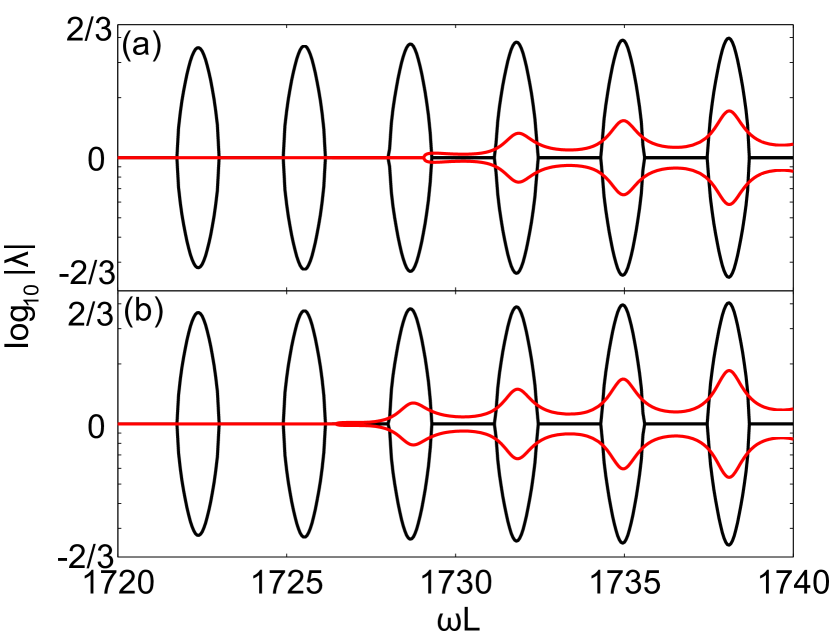
These two conditions for the transition and for the two phases of the S-matrix do not coincide (see Figs. 7 and 8(a)) unless an ATR is tuned to occur at the phase boundary of as we have shown in Fig. 6. We see that for this simple heterostructure, has a single transition to the broken symmetry phase (for a fixed ), while has a series of transitions corresponding to entering and leaving the broken-symmetry phase in the high frequency regime (Fig. 7). Each of these transitions begins at one of the two ATRs and ends at the other; thus the centers of the broken symmetry regions are spaced by the free spectral range of the unitary cavity. These “lozenges” of broken symmetry phase barely change when is varied; repeatedly enters and leaves the symmetric phase as we tune . In contrast, the single transition point of moves substantially to lower frequency as increases; once it enters the broken-symmetry phase, it never re-enters the symmetric phase at any higher frequency. This indicates that , not , is measuring the breaking of symmetry.
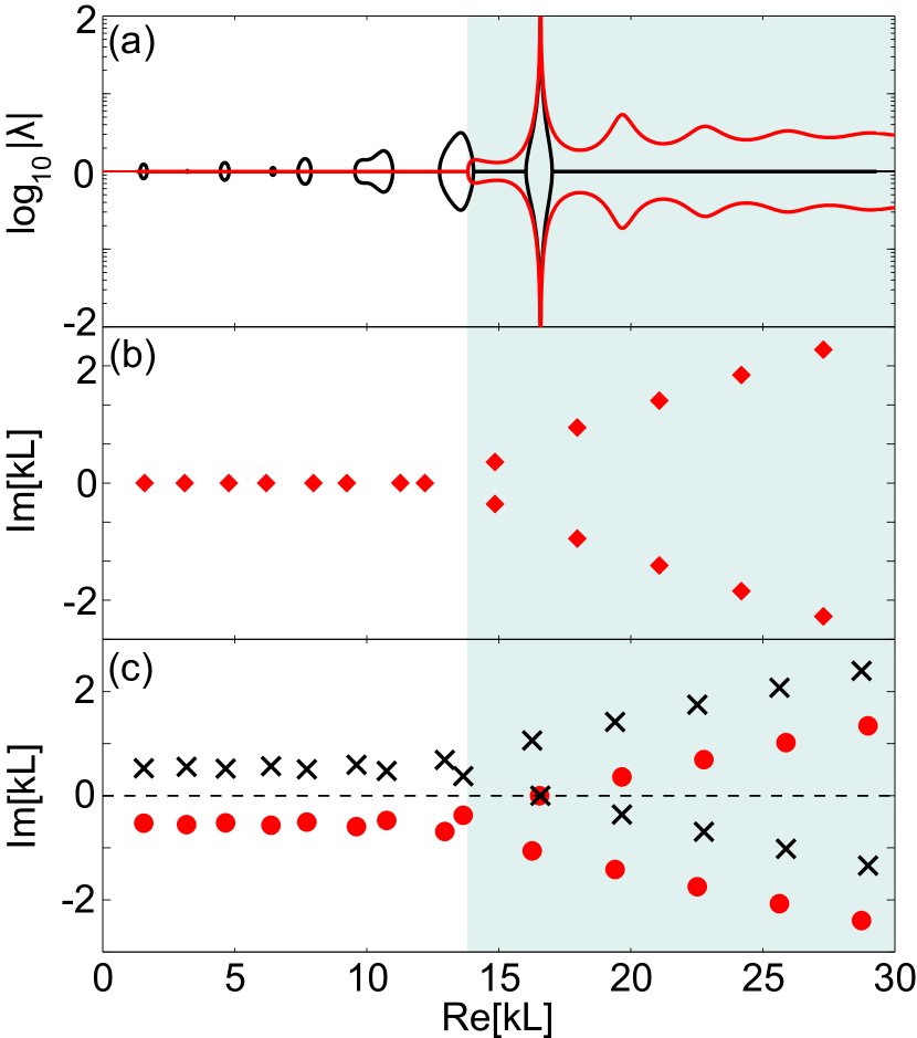
In Fig. 8 we show the decisive comparison. If we simply take the heterostructure shown in Fig. 2a, and impose Dirichlet or Neumann boundary conditions at the boundaries to the continuum, we have a non-Hermitian discrete eigenvalue problem with symmetry. Its energy spectrum (expressed as complex frequencies) makes transitions between real and complex conjugate pairs (Fig. 8(b)), in a manner which perfectly follows the behavior of the eigenvalues of and but not of (Fig. 8(a)). Moreover, in Fig. 8(c) we show the poles and zeros of the S-matrix; their symmetric distribution around the Im axis is a consequence of the symmetry. Before the transition of the poles have approximately the same value of Im as for the passive system, but just at the transition of there is an anti-crossing in the complex plane and half begin moving toward the real axis and the other half recede further down in the complex plane CPALaser ; schomerus2 . For Im the system is very near the CPA-laser point for which a pole and zero coincide on the real axis. The eigenvalues of both and diverge/vanish at this point because and all diverge at the lasing transition. Interestingly, for this value of Im, there are no ATRs after the lasing transition and for all larger ; the reasons for this are discussed in the Appendix. The same correspondence between the broken symmetry phase of and the analogous closed system hamiltonian holds for more complex heterostructures, such as that of Fig. 2(c), where has multiple broken phases closed . Thus we believe that at least for the 1D case, there is a unique definition of the S-matrix, under which its transitions actually reflect the symmetry breaking in the underlying non-Hermitian Hamiltonian.
VI Conclusion
We have derived generalized unitarity relations for the S-matrix of arbitrary 1D -symmetric photonic heterostructures, including a conservation relation between the transmittance and the left and right reflectances. This conservation relation can be easily tested in experimental structures and used as a criterion of how precisely one has realized the symmetry. In addition, the conservation relation leads to a simple criterion for identifying the exceptional point(s) at which the symmetry is spontaneously broken or restored. These exceptional points are shown to be closely related to the -symmetry breaking transition of the underlying effective Hamiltonian of the system.
VII Acknowledgments
We thank Tsampikos Kottos, Stefan Rotter, Kostas Makris, Hamidreza Ramezani, Zheng Lin, Hui Cao, Demetri Christodoulides, and Carl West for helpful conversations. This work was supported by NSF grant No. ECCS 1068642.
Appendix A Properties of simple gain-loss heterojunction
The heterostructure shown in Fig. 2(a), which consists of two uniform slabs of equal length and index is the simplest example one can study of the class of 1D symmetric photonic heterostructures, and it has been treated previously in CPALaser ; mostafazadeh . We will refer to this structure as the “simple heterojunction” (SH), and it is described by the transfer matrix (4) with , , and , where
| (20) | |||||
| (21) | |||||
| (22) |
and is the complex optical path inside the left half. Since are real, so are and , and it is straightforward to check that (5) holds. This transfer matrix leads to certain simple properties. First, as mentioned in the text, the SH has no trivial ATRs as we will show in subsection A.1. Second, below the symmetry breaking point it has many ATRs, roughly two per free spectral range of the passive resonator. Above the symmetry breaking transition it still has ATRs until it passes the lasing transition after which they disappear in the limit . We will discuss this behavior and contrast it with more complex heterostructures in subsection A.2.
A.1 Absence of trivial ATRS
The SH can be treated as having an air gap of vanishing width in between the gain and loss regions. Hence the absence of trivial ATRs is a consequence of the absence of reflectionless transmission resonances of such uniform amplifying or attenuating slabs in air. Below we first discuss in general the transmission resonances of a uniform slab of refractive index and length embedded in two semi-infinite media of index and .
For this simple setup the transfer matrix defined in Sec. II (; see Fig. 1) takes the form
| (23) |
where can be complex. A transmission resonance of an incident beam from the left side requires and
| (24) |
For the gain and loss regions in SH, when treated as being separated by an infinitely thin air gap, while . We immediately see that Eq. (24) cannot be satisfied because due to the finite imaginary part of . This holds independent of () and (see Fig. 9). This finding is confirmed by calculating the reflectance directly (see Fig. 9(a)). The same analysis can be extended to the slightly more complicated case shown in Fig. 2(c), where all the ATRs are also found to be “non-trivial” as confirmed again by calculating the reflectances of the sub-units directly. We note, however, that trivial ATRs do exist in some structures. An example is the concatenation of even numbers of SHs.
A.2 Asymptotic properties of ATRs in the simple heterojunction
In this main text we noted that ATRs for the SH disappear soon after the lasing threshold is passed in the broken symmetry phase of (see Fig. 10(a)). To understand this observation, we study the behaviors of and in the large limit. The reflection coefficient from the “loss” side of the heterostructure approaches the value given by the Fresnel formula, , due to the suppression of interference effects by strong absorption. Surprisingly, the asymptotic value of the reflection coefficient from the “gain” side, , turns out to be the inverse of the Fresnel formula. This can be explained from the analysis shown by the inset of Fig. 10(a). Due to the strong loss inside the “loss” side of the cavity, is given by the Fresnel relation , implying is much larger than in the large limit. Therefore, the scattering at the air-gain interface is approximately the time reversed process as if the “gain” side (which is the “loss” side in the time-reversed picture) were semi-infinite, i.e. with incident amplitude and reflected amplitude in the air and transmitted amplitude , satisfying the Fresnel relation. The reflection coefficient in the original problem is then . Thus in this limit, which implies from Eq. (9) and ATRs do not exist.
In more complicated structures ATRs can take place in this limit. For example, the reflection coefficient connecting and approaches zero at the transmission resonances of the passive region in Fig. 2(c). The analysis above then breaks down and sharp changes of the transmittance and reflectances take place at these frequencies as shown in Fig. 10(b). These transmission resonances through the passive region is a special set of solutions of Eq. (24). They require and , and the transmission resonances occur at
| (25) |
In the frequency range shown in Fig. 2(c) where is small, these transmission resonances do not lead to ATRs of the whole heterostructure due to the multiple interferences taking place inside the gain and loss sub-units. In the large limit shown in Fig. 10(b), however, these multiple interferences are suppressed due to strong absorption/amplification, and ATRs arise from the resonances given by (25). Note that these ATRs are still “non-trivial” as the frequencies given by (25) are not the transmission resonances of the gain or loss sub-unit in the absence of the other.
For the purpose of completeness, we mention a few more cases where transmission resonances of a single uniform slab (i.e. the solutions of Eq. (24)) exist. When can be treated as real (with negligible absorption and no gain), two types of solutions of (24) can be found. The first one is well-known, , which requires ; the second one is less well-known, , which requires . It is easy to convince oneself that no other types of solution exist for real indices. As one slowly increase the gain or loss strength in the scattering layer, approximate transmission resonances can still be found, but their reflectances gradually increase and eventually become detectable. In Ref. surfaceMode a different case was studied where . By noticing that cannot satisfy the above equation and is real, Eq. (24) can be reduced to
| (26) | |||||
| (27) |
It describes the transmission resonance from a loss/gain media to air through a passive slab, which gives rise to the novel “surface” lasing modes introduced in Ref. surfaceMode .
References
- (1) C. M. Bender and S. Boettcher, Phys. Rev. Lett. 80, 5243 (1998).
- (2) C. M. Bender, S. Boettcher, and P. N. Meisinger, J. Math. Phys. 40, 2201 (1999).
- (3) C. M. Bender, D. C. Brody, and H. F. Jones, Phys. Rev. Lett. 89, 270401 (2002).
- (4) R. El-Ganainy, K. G. Makris, D. N. Christodoulides, and Z. H. Musslimani, opt. Lett. 32, 2632–2634 (2007).
- (5) K. G. Makris, R. El-Ganainy, D. N. Christodoulides, and Z. H. Musslimani, Phys. Rev. Lett. 100, 103904 (2008).
- (6) C. E. Rüter, K. G. Makris, R. El-Ganainy, D. N. Christodoulides, M. Segev, and D. Kip, Nat. Phys. 6, 192 (2010).
- (7) M. C. Zheng, D. N. Christodoulides, R. Fleischmann, and T. Kottos, Phys. Rev. A 82, 010103(R) (2010).
- (8) A. Guo, G. J. Salamo, D. Duchesne, R. Morandotti, M. Volatier-Ravat, V. Aimez, G. A. Siviloglou and D. N. Christodoulides, Phys. Rev. Lett. 103, 093902 (2009).
- (9) Z. H. Musslimani, K. G. Makris, R. El-Ganainy, D. N. Christodoulides, Phys. Rev. Lett. 100, 030402 (2008).
- (10) H. Ramezani, T. Kottos, R. El-Ganainy, D. N. Christodoulides, Phys. Rev. A, 82, 043803 (2010).
- (11) A. Mostafazadeh, Phys. Rev. Lett. 102, 220402 (2009).
- (12) S. Longhi, Phys. Rev. A, 82, 031801 (R) (2010).
- (13) Y. D. Chong, Li Ge, and A. D. Stone, Phys. Rev. Lett., 106, 093902 (2011).
- (14) H. Schomerus, Phys. Rev. Lett. 104, 233601 (2010).
- (15) Gwangsu Yoo, H.-S. Sim and H. Schomerus, Phys. Rev. A 84 063833 (2011).
- (16) Y. D. Chong, Li Ge, H. Cao, and A. D. Stone, Phys. Rev. Lett. 105, 053901 (2010).
- (17) W. Wan, Y. D. Chong, L. Ge, H. Noh, A. D. Stone and H. Cao, Science 331, 889 (2011).
- (18) A. Mostafazadeh, J. Math. Phys. 45, 932 (2004).
- (19) Z. Lin, H. Ramezani, T. Eichelkraut, T. Kottos, H. Cao, and D. N. Christodoulides, Phys. Rev. Lett. 106, 213901 (2011).
- (20) Here we assume the refractive indices , on the left and right sides of the 1D structure are the same. A more general relation is ; see A. Yeh, Optical waves in layered media (Wiley, New York, 1988).
- (21) When the two incident amplitudes and the two outgoing amplitudes become decoupled, which gives rise to the CPA-laser points and the reflection and transmission coefficients become infinite. However, the results derived in the main text are still valid at these points with appropriate choices of limiting procedures.
- (22) S. Longhi, Phys. Rev. Lett., 107, 033901 (2011).
- (23) A. D. Stone et al., unpublished.
- (24) There may seem to be a number of frequencies in Fig. 2(b) at which and , but it is a coincidence as the transmission phase oscillates around and we have chosen to be an integer.
- (25) Alternatives include and , but they suffer from a sign uncertainty, an aritifact different from the two physical possibilities in .
- (26) C. W. J. Beenakker, Rev. Mod. Phys. 69, 731-808 (1997).
- (27) F. Cannata, J. P. Dedonder, A. Ventura, Ann. Phys. 322, 397 (2007).
- (28) S. Rotter et al., unpublished.
- (29) Li Ge, Y. D. Chong, S. Rotter, H. E. Türeci, and A. D. Stone, Phys. Rev. A 84, 023820 (2011).