Coherent spin dynamics of electrons and excitons in nanostructures (Review)
Abstract
The studies of spin phenomena in semiconductor low dimensional systems have grown into the rapidly developing area of the condensed matter physics: spintronics. The most urgent problems in this area, both fundamental and applied, are the creation of charge carrier spin polarization and its detection as well as electron spin control by nonmagnetic methods. Here we present a review of recent achievements in the studies of spin dynamics of electrons, holes and their complexes in the pump-probe method. The microscopic mechanisms of spin orientation of charge carriers and their complexes by short circularly polarized optical pulses and the formation processes of the spin signals of Faraday and Kerr rotation of the probe pulse polarization plane as well as induced ellipticity are discussed. A special attention is paid to the comparison of theoretical concepts with experimental data obtained on the -type quantum well and quantum dot array samples.
I Introduction
The studies of spin effects in semiconductors have started in the end of 1960s after the discovery of the optical orientation of electron spins in Silicon lampel68 . The investigation of circular polarization of luminescence at a constant wave pumping as a function of magnetic field made it possible to establish the main mechanisms of the nonequilibrium spin generation of free and localized charge carriers in semiconductors and to study the processes of electron and hole spin relaxation, as well as to explore the interaction of electron and nuclear spin systems optor:eng .
An interest in the studies of spin dynamics in bulk semiconductors and semiconductor low dimensional systems has revived in the end of 90s of the last century. The pump-probe method PhysRevLett.55.1128 ; Zheludev1994823 has played a role of no small importance in it, this method has enabled scientists to study spin coherence with temporal resolution. It is certain, that the precision measurements of ultralong spin relaxation times in bulk materials Kikkawa98 , quantum wells Kikkawa29081997 and quantum dots A.Greilich07212006 , a visualization of spin precession, relaxation brand02 ; leyland06 ; PhysRevB.80.241314 and the spin transport in bulk materials and nanostructures Kikkawa1999 ; kato04 ; PhysRevLett.94.236601 carried out in the framework of this two beam technique, have laid the foundation of spintronics: a new area of science and technology, where the electron spin along with its charge finds application for the information transfer and processing, see awschalom_book ; dyakonov_book ; ssc:optor and references therein.
The essence of the pump-probe method is schematically shown in Fig. 1(a). The core of this technique is as follows: a sample is subject to a sufficiently strong circularly polarized pump pulse, whose absorption causes the spin orientation of charge carriers and their complexes: excitons, trions. After a certain delay, a much weaker linearly polarized probe pulse arrives at the sample. The presence of the nonequilibrium spin polarization in the sample makes the system optically active: the polarization plane of the probe pulse rotates in the transmission geometry (magnetooptical or spin Faraday effect) and in the reflection geometry (spin Kerr effect) aronovivchenko:eng . Moreover, the probe pulse passed and reflected from the sample acquires partially a circular polarization, that is the ellipticity. The polarization plane rotation angle as well as induced ellipticity are proportional to the spin polarization in the system. If the sample is subject to a magnetic field in Voigt geometry (field is applied in the plane perpendicular to the pump and probe pulses propagation direction), the spins of electrons, holes and their complexes precess around the external field. Therefore, the spin ellipticity, Faraday and Kerr rotation angles oscillate as functions of the delay between the pump and probe pulses, reflecting spin precession, see inset in Fig. 1(a) and Fig. 2(a).
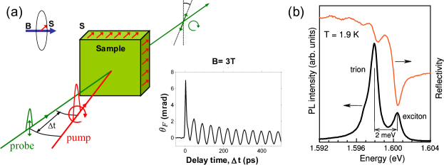
Pump-probe method is very sensitive to the momentary values of electron and hole spin polarization in semiconductors. The dependence of the signals on the temporal delay between the pulses allows one to study straightforwardly the spin dynamics of electron system in solids and extract spin precession frequencies, spin relaxation and decoherence times directly from the experimental data. It is shown in Fig. 2, where two typical curves of Kerr rotation signal as function of delay measured in the CdTe/CdMgTe quantum well structure are presented [Fig. 2(a)] along with the results of its treatment [Fig. 2(b) and (c)]. In Fig. 2(b),(c) the dependence of spin precession frequency and electron spin dephasing time on magnetic field is shown. The detailed analysis of the spin signals temporal dependence measured in the pump-probe technique is presented below in Sec. IV. We just mention here, that as distinct from the methods based on polarization of luminescence studies, in the pump-probe technique the charge carriers spin dynamics can be studied on the time scales which exceed by far the luminescence decay time. Moreover, application of an additional circularly or linearly polarized ‘‘control’’ pulse PhysRevB.77.165309 ; phelps:237402 ; Greilich2009 ; zhukov10 opens up possibilities to control spin dynamics by nonmagnetic means.

Among the systems of every sort and kind, where the pump-probe technique is successfully applied, the special place is taken by the structures with singly charged quantum dot arrays or quantum well structures with low density electron gas, where the condition is fulfilled Chen20101803 . Here is two-dimensional electron density, is the Bohr radius. Mentioned systems possess important features: firstly, due to electron localization in quantum dots or at quantum well potential fluctuations, the spin relaxation times of resident carriers are strongly increased, secondly, in these very systems, the role of Coulomb interaction is high, and Coulomb complexes: excitons and trions manifest themselves most brightly [Fig. 1(b)]. It makes possible to study the microscopic processes responsible for the excitation, control and detection of spin polarization with spectral sensitivity, while long spin relaxation times are important for device applications in the field of spintronics.
In these structures one deals with an electron ensemble. On one hand, its inevitable inhomogeneity results in an effective dephasing of electron spins, e.g., in magnetic field due to the spread of electron -factor values. The influence of inhomogeneity can be avoided by studying single quantum dots mikkelsen07 ; atature07 , however, a wide application of the pump-probe method for the single dots is quite hampered owing to weak signals and small ‘‘signal-to-noise’’ ratio. On the other hand, in quantum dot ensembles the electron spin precession mode-locking is observed, in which case about spins precess with commensurable frequencies A.Greilich07212006 , which allows in a certain degree to overcome the inhomogeneity effects. In the review we focus on these particular systems: singly charged quantum dots and quantum wells with low density electron gas.
II Macroscopic description of spin coherence generation and detection
The semiphenomenological theory of resident charge carriers spin coherence generation and detection processes in quantum wells and quantum dot ensembles is given in this Section. The consistent quantum-mechanical description of the interaction of short optical pulses with localized carriers is presented below in Sec. III. Here we focus on simple physical models, describing spin generation at trion and exciton excitation, as well as on the macroscopic description of the spin Faraday, Kerr and ellipticity effects in quantum well and quantum dot structures.
II.1 Resident carriers spin orientation mechanisms
II.1.1 Resonant excitation of trions
In quantum wells with a low density electron gas and in singly charged quantum dots the optical absorption results in the formation of trions: the three particle complexes, consisting of an electron pair and a hole. In the absence of an external magnetic field or in moderate magnetic fields (up to several Tesla) the total spin of the electron pair in the trion ground state equals to zero, therefore prima facie it is not clear whether the resident electrons spin coherence can arise in the system.
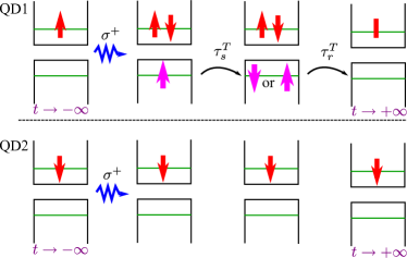
One can be convinced, however, that the trion formation process is spin-dependent. Indeed, in accordance with the selection rules for the quantum well and self-organized quantum dot structures the absorption of the circularly polarized photon is accompanied by the formation of electron () and heavy-hole () pair: for polarized light propagating in the positive direction of axis and for polarized quantum. Here , are the projections of electron and hole spins onto axis. Therefore, e.g., only electrons with spin component being equal to participate in the trion formation for the polarized pump pulse, as it is schematically shown in Fig. 3.
Let us assume now that the hole-in-trion spin relaxation time is small as compared with the trion radiative lifetime . Hence, at trion recombination the depolarized electrons return to the system. Thereby, due to the trion formation, pump pulse depolarizes electrons with the spin component and does not affect electrons with the spin component . Since at low temperatures resident electron spin relaxation time ns and exceeds by far the trion lifetime ps dzhioev97:eng ; Kikkawa98 ; A.Greilich07212006 ; fokina-2010 , after the trions recombination, the imbalance of electrons with opposite spin projection arises, that is spin polarization shabaev:201305 ; PhysRevB.68.235316 . Note, that the spin accumulated in the system is directed in the same way as the spin of photocreated electrons: in opposite to axis direction at the pumping and along axis direction in the case of pumping.
Specified mechanism of the long living electron spin polarization generation at a trion resonant excitation is quite analogous to the classical spin pumping of majority carriers in semiconductors dp_orientation:eng . If hole spin relaxation is suppressed, , then in the absence of magnetic field the electron spin orientation in uneffective: spin of electrons returning after trions recombination exactly compensates the polarization of carriers which did not pariticipate in the trions formation. The magnetic field presence results in the electron and hole spin precession. For instance, in quantum well structures where the in-plane heavy hole -factor is small Mar99 , the trion state remains unchanged, while electron spin rotates. Hence, after the trion recombination the spin compensation is broken in the magnetic field which leads to the appearance of resident electron spin polarization kennedy:045307 ; PhysRevLett.94.227403 .
We introduce the electron spin pseudovector , describing mean values of spin components of the charge carriers ensemble in the quantum well or in the quantum dot array. Trion spin states can also be characterized by an effective spin , where is the number of trions with the spin projections onto axis equal to , respectively. Kinetic equations describing spin dynamics of excitons and trions after the system photoexcitation have form zhu07 ; PhysRevB.75.115320
| (1a) | |||
| (1b) | |||
| (1c) |
It is assumed here that the magnetic field is applied along axis in the structure plane, therefore component of electron spin ,
| (2) |
is the electron spin precession frequency in the external field, is the electron -factor. A simple form of Eq. (1c) for the trion spin follows from the fact that the hole spin rotation angle during its lifetime is small as compared with that of an electron, inasmuch as hole -factor in the quantum well or dot plane is small as compared with electron -factor (general case is considered in Ref. sokolova09 ). Following relations serve as initial conditions for the system (1)
| (3) |
where is the number of photoexcited trions. The system of kinetic equations (1) describes well the spin beats in the quantum well structures containing low density electron gas zhu07 ; ast08 .
Here and in what follows we focus on -type structures. In -type quantum wells and quantum dots the physical principles of hole spin coherence excitation are analogous to those considered above. The specifics of these structures lies in the fact, that the hole -factor in the structure plane is much smaller than the -factor of the electron, which leads to some features of spin dynamics Korn2010415 ; korn_njp ; Machnikowski10 ; PhysRevB.81.045322 .
To conclude this Subsection we note, that the physical origin of the resident electron spin orientation at the resonant excitation of trion: spin-dependent trion formation at the circularly polarized light action and the imbalance formation between the electron spins returning after the trion recombination and those, which did not participate in the trion formation, is the same for quantum well and quantum dot structures shabaev:201305 ; kennedy:045307 . The specifics of electron and hole spin orientation at the nonresonant excitation of singly charged quantum dots, including negative circular polarization of luminescence phenomenon, was studied in detain in number of works dzhioev98:eng ; cortez02 ; Ignatiev05 ; laurent06 ; springerlink:10.1134/S0030400X09030114 .
II.1.2 Resonant excitation of excitons
The line responsible for exciton resonance is present in the optical spectra of quantum well structures containing low density electron gas, see Fig. 1(b). Let us briefly analyze the mechanisms of resident electron spin orientation at the exciton excitation in these systems.
If the system temperature expressed in the units of energy is small compared to the trion binding energy, the photocreated excitons form trions capturing those electrons from the resident ensemble, whose spin orientation is opposite to that of electron-in-exciton. The following scenario of resident electron spin coherence generation is quite analogous to the described above for resonant trion excitation.
It was shown in Ref. zhu07 (see also fokina-2010 ) that the effective resident electron spin orientation is even possible in situations where the trion formation is impossible, but excitons are still stable, e.g. at temperatures exceeding trion binding energy or in a relatively dense electron gas. In these cases, the exchange scattering processes of resident electrons by excitons are important tarasenko98 .
The resident charge carriers spin coherence excitation scenario consists of two stages: first, polarized pump pulse forms excitons with definite spin projections of electron and hole (for example, , for polarized pulse). At a second stage, the spin transfer from electrons-in-excitons to resident electrons takes place due to exchange flip-flop scattering. At that, the resident electrons turn out to be partially spin polarized, and for relatively fast hole spin relaxation excitons recombine regardless the electron spin orientation in excitons. Mathematical description of this scenario is presented in Ref. zhu07 .
We note that the long living spin coherence may arise also at the nonresonant excitation of the quantum well structures by circularly polarized light. Microscopic mechanisms of these processes are related both the excitons and trions formation during the relaxation of photocreated carriers, and with the classical optical pumping of electron spins zhu07 ; ast08 .
II.2 Detection of charge carriers spin coherence
The spin polarization of electrons and electron-hole complexes leads to an optical activity of a medium: interaction efficiencies for right- and left- circularly polarized electromagnetic waves with such a system turn out to be different. The response of the quantum well structures and planar quantum dot arrays to the electromagnetic radiation can be conveniently characterized by frequency and polarization dependent light reflection coefficient, , which in the vicinity of the exciton or trion resonance has the form
| (4) |
Here is the probe pulse frequency, subscripts and refer to and components of the pulse, respectively, is the exciton or trion resonant frequency, is its radiative and is its nonradiative damping. The difference of the resonance parameters for right- and left- circularly polarized radiation is related with the spin polarization of charge carriers:
and the spin Faraday and Kerr rotation as well as induced ellipticity signals are formed owing to this very difference. It is important to note that in contrast to the classical magnetooptical effects sizov_book , the spin Faraday and Kerr rotation signals as well as spin ellipticity are determined just by the components of nonequilibrium spin polarization of electrons, rather than by an external magnetic field. The signals sensitivity to the electron spin component is determined by the selection rules related with the heavy hole excitation under normal incidence of light. One can investigate the dynamics of all spin pseudovector components making use of the light hole related resonances Kosaka2009 .
The connection between the trion and exciton resonance parameters with the resident electron spin polarization is analyzed in the following Subsections. The structure with high density electron gas where electron-hole complexes are not stable and the response character differs from the resonant one, described by expression (4), is also considered below.
Let us establish the link between the light reflection coefficients and the spin Faraday, Kerr and induced ellipticity signals. Assume that the probe pulse propagates along the structure normal, i.e. axis, and let its electric field be polarized along . In Faraday effect studies the probe pulse is split into two ones being linearly polarized at angles with respect to the initial polarization. The time integrated difference of intensities of these pulses as function of the pump-probe delay is measured. Hence, the spin Faraday rotation signal equals to yugova09
| (5) |
Here , axes are oriented at with respect to the initial frame , ; and are the components of the field transmitted through the sample. The integration in Eq. (5) is carried out over the measurement time, , which exceeds by far all other time constants in the system. The Kerr effect is studied in the reflection geometry and its magnitude is defined as
| (6) |
where the superscript indicates, that the fields of reflected wave enter Eq. (6). In pump-probe experiments the induced ellipticity effect is also measured, which in the transmission geometry, is described by the following expression
| (7) |
In this case the difference of transmitted wave circularly polarized components, , is analyzed.
In the single quantum well structure and single layers of quantum dots the transmission coefficients through the layer, , are related with the reflection coefficients, , by the simple expression
Since in real systems and as a rule, the spin Faraday and ellipticity signals are described by a simplified formula zhu07 ; fokina-2010 :
| (8) |
The Kerr effect is associated with the light reflection from the sample, therefore, it is determined by the interference of the beams, reflected from the sample surface (vacuum-sample boundary) and from the well or dot layer. The interference brings about an additional phase equal to , where is the cap layer thickness (distance from the boundary with vacuum and the well or dot array) and is the light wave vector in the cap layer springerlink:10.1134/1.1130188 . As a result, Kerr signal is related with the reflection coefficients from the system as zhu07
| (9) |
We stress that the description of the spin Kerr and Faraday effects, as well as the induced ellipticity in the macroscopic approach can be applied not only for the analysis of experimental data obtained in the pump-probe technique, but also to study the spin dynamics and magnetization at the constant wave pumping PhysRevB.74.073407 , as well as in quasi equilibrium conditions for magnetic and superconducting structures gourdon:230 .
II.2.1 Detection at trion resonance
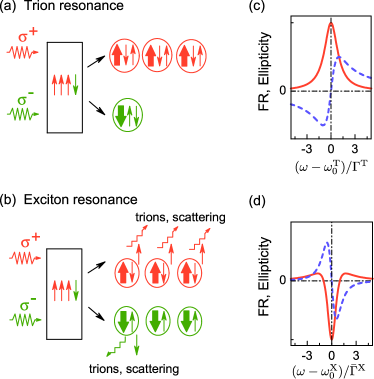
The trion oscillator strength in and circular polarizations is directly proportional to the number of electrons with a given spin projection onto axis, astakhov00 ; astakhov02 . Indeed, as discussed in Sec. II.1.1 the resident electrons with take part in the singlet trion formation by polarized light. It is illustrated in Fig. 4(a). Therefore, the trion radiative damping being proportional to its oscillator strength can be represented in the form:
Here is a constant, is the exciton radiative damping. Trion resonance frequency renormalization due to electron spin polarization and the modification of its nonradiative damping are negligibly small because they are determined by an exchange interaction of an electron and hole. The trion resonance contribution to the spin Faraday and ellipticity signals can be written as fokina-2010
| (10) |
We took into account that in derivation of Eq. (10). Hence, spin ellipticity and Faraday rotation signals detected at the trion resonance are proportional to the total electron spin component. Frequency dependence of these signals calculated according to Eq. (10) is shown in Fig. 4(c). It is seen, that the Faraday rotation signal is an odd function of the detuning between the probe pulse and the trion resonance frequencies, while the ellipticity signal as an even function. Physically, it is related with the fact that the spin ellipticity is related with the absorption dichroism which takes its maximum value at the resonance, while Faraday rotation is related with the refraction of electromagnetic waves in the medium.
II.2.2 Detection at exciton resonance
Mechanism of the Faraday, Kerr and ellipticity effects formation at the exciton resonance detection is different from that at trion resonance detection. As we noted above, at low temperatures in low density electron gas the exciton lifetime is determined by the electron capture and trion formation process. Therefore, the nonradiative damping of the exciton excited by the light with a given circular polarization can be presented as [Fig. 4(b)]
where is the spin polarization independent exciton damping, is a coefficient determined by the trion formation rate. An additional contribution to is given by the spin-dependent electron-exciton scattering processes tarasenko98 . An exchange (Hartree-Fock) interaction of electron-in-exciton and of resident electron may give rise to the exciton resonance frequencies renormalization, and at high pumping and probing intensities, the exciton-exciton scattering may play a role, see, e.g., Refs. PhysRevLett.75.2554 ; wang04 ; shen05 ; PhysRevB.72.245202 ; PhysRevB.74.125316 ; PhysRevLett.103.056405 . Restricting ourselves with the low temperatures and low pulse powers limit we obtain from Eq. (4)
| (11) |
Here, similarly to the derivation of Eq. (10), we took into account that . The frequency dependence of the Faraday rotation and ellipticity spin signals is shown in Fig. 4(d).
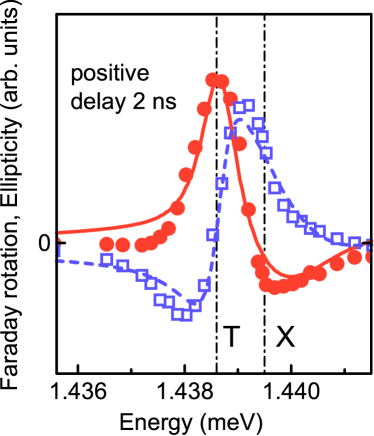
Comparison of Eqs. (10) and (11) shows that the ellipticity signs at exciton and trion resonances are opposite. Indeed, an excess of electrons with the spin projection () leads to a stronger absorption of polarized photons at the trion resonance and to a weaker absorption at the exciton one. Such an ellipticity sign change was experimentally observed in InGaAs/GaAs quantum well structure fokina-2010 . Figure 5 represents the dependence of Faraday rotation signal on the probe pulse frequency (squares are the experiment, dashed line is the theory) and that of ellipticity signal (circles are the experiment, solid line is the theory). The signals were measured at the long enough positive delays (about 2 ns), which markedly exceed the lifetimes of photoexcited excitons and trions, therefore these signals correspond to the resident carrier spin polarization. It is seen that the ellipticity signals at the trion and exciton resonances have opposite signs and the whole spectral dependence is rather well described by the macroscopic theory outlined above. The experiment and calculation details as well as the fitting parameters values are presented in Ref. fokina-2010 .
We note that a sign change of the spin signals is also observed if one uses resonances provided by the electron-light-hole complexes instead of those with the heavy hole ast08 ; Chen20101803 . Such a sign change is related with the change of the selection rules for optical interband transitions.
II.2.3 Quantum wells with high density electron gas
In structures containing the electron gas of high density, where , or at high temperatures, the excitons and trions are unstable, and the light absorption is accompanied by free electron-hole pairs formation. In this case Eq. (4) is unapplicable. The main mechanism of spin Faraday, Kerr and ellipticity signals formation in these systems is the polarization-dependent blocking of optical transitions caused by the filling of electron spin states. We make use of the general expression for the doped quantum well reflection coefficient (see e.g., Ref. PhysRevB.76.045320 ), which in the case of small value and for negligibly small Coulomb interaction takes form
| (12) |
Here is a constant introduced in Eq. (10) of Ref. PhysRevB.76.045320 , are the distribution functions of the carriers with spin components , is the electron-hole reduced mass ( is the electron effective mass, is that of the hole), is the effective band gap found with allowance for electron and hole size quantization, is the nonradiative damping of electron-hole pair. Assuming electron spin polarization to be small, one can obtain (c.f. zhu07 )
| (13) |
where is the distribution function of the electron spin component. It follows from Eq. (13) that for degenerate electrons where the Fermi energy , temperature , expressed in the energy units, and nonradiative damping satisfy the conditions
| (14) |
where is the absorption edge energy, is the electron spin density. The main contribution to the spin signals in provided by Fermi level electrons which gives rise to the resonant character of reflection coefficients. Moreover, it is the imbalance of electrons with and which determines the difference of and probe pulse components interaction efficiencies with the system. For instance, if , then component of the probe pulse is absorbed better than one. As a result, the spectral dependence of the spin Faraday and ellipticity signals in dense electron gas is analogous to that observed at a trion resonance.
Let us also analyze the contribution to the Faraday and ellipticity signals made by the shifts of electron energy levels in the spin-polarized electron gas due to exchange interaction (Hartree-Fock effect). The relative shift of optical transition energies in and polarizations can be recast as PhysRevB.60.4826
where is the Fourier transform of the Coulomb potential of interaction between charge carriers. Hartree-Fock contribution to the ellipticity and Faraday rotation spin signals writes in the form
| (15) |
Calculation shows that for degenerate electrons and low degree of spin polarization
| (16) |
Here the gas parameter in introduced, in the wave vector of electron at the Fermi surface, is the static dielectric constant. Function is defined as follows PhysRevB.60.4826 :
It is important to note that in quantum well structures the contributions caused by the optical transitions blocking and the exchange interaction differ by the common factor and sign only. In a high-density electron gas , and Hartree-Fock contribution, Eq. (16), is small as compared with the contribution from the transitions blocking described by Eq. (14). In real structures, however, can be on the order of unity and both effects can make comparable contributions to the spin Kerr, Faraday and ellipticity signals. Experimental investigations of many-body effects in the pump-probe method and, in particular, the renormalizations caused by the exchange interaction of electrons were carried out in Ref. Barate2010 .
II.2.4 Dynamics of electron and magnetic ion spins in CdMnTe quantum wells
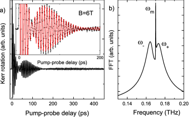
In the presence of several spin subsystems: electron, hole and nuclear, the spin Faraday and Kerr rotation signals, as well ellipticity bear information of spin dynamics in all subsystems. The case where one of the subsystems does not directly interact with light but gives rise to the spin signals via interaction with electrons is of special interest. Possible realizations of this situation are the Faraday rotation induced by spin polarized nuclei considered theoretically for bulk semiconductors in Ref. artemova85 (see also Refs. J.M.Kikkawa01212000 ; PhysRevLett.99.056804 ), and the Kerr rotation induced by the Manganese ions magnetization in diluted magnetic structures CdMnTe, ZnMnSe PhysRevLett.55.1128 ; PhysRevB.50.7689 ; PhysRevB.56.7574 ; PhysRevB.78.081305 .
Experimental dependence of the Kerr rotation signal as function of the temporal delay between the pump and probe pulses obtained in Ref. PhysRevB.78.081305 in diluted magnetic CdMnTe quantum well structure are presented in Fig. 6(a). Spin signal shows a complex temporal dependence whose Fourier analysis presented in Fig. 6(b) evidences the presence of three spin precession frequencies. According to the results of Ref. PhysRevB.78.081305 two of these frequencies and correspond to the mixed (collective) spin precession modes of electrons and magnetic ions. In fact, the exchange interaction between the resident electrons and -electrons of Mn ions results in the coherent energy transfer between them and to the spin beats at a difference frequency , which are clearly visible in Fig. 6(a). Spin signals from the mixed modes decay during the electron spin relaxation time being on the order of 100 ps. These contributions to the Kerr signal are proportional, according to Eqs. (14), (16), to the spin polarization of electrons in the corresponding spin precession mode.
Third narrow peak in the spin beats Fourier spectrum at a frequency corresponds to those Mn spin precession modes which are not coupled with conduction electrons. The modes in question are excited by the pump pulses and contribute to the Kerr rotation signal owing to the exchange interaction with holes. Indeed, spin polarized photocreated hole generates an effective magnetic field oriented along axis, which results in the momentary tilt of Mn spins from the external magnetic field direction and ‘‘triggers’’ their precession CrookerPRL96 . The polarization of magnetic ions, on the other hand, results in the change of optical transition energies in circular polarizations and , being proportional to , where is the magnetic ions magnetization and is the effective interaction constant of the exchange interaction between the Mn and the hole averaged over the distribution of magnetic ions and hole wavefunction PhysRevB.50.7689 . It can be shown, that the dependence of the spin signals on the probe pulse frequency in sufficiently dense electron gas is determined by the expressions analogous to formulae (9) and (16)
| (17) |
The damping time of this contribution to the spin signal is considerably larger than that of collective modes since the spin relaxation of Mn ions, which are uncoupled from electrons, is slow.
We note in conclusion of this Subsection that the spin precession of magnetic ions is directly visible from the pump-probe signals, see long living signal in Fig. 6(a), because -factor of Mn is close to 2, and the coupling constants of electron and holes with -electrons of Mn ions are relatively large. Another situation is realized for the nuclei: in the pump-probe experiments the nuclear spin precession is not seen, while dynamic nuclear polarization is observed as the Overhauser shift of electron spin precession frequency Li2010450 .
III Microscopic description
The models of spin coherence excitation and detection set out in Sec. II describe successfully qualitative specifics of spin signals obtained in the pump-probe method in quantum well and quantum dot array structures. In this Section the microscopic theory of resident charge carriers spin orientation by short pulses in quantum dots is put forward. This theory is based on a model of a two level system. We show that optical pulses do more than merely excite spin polarization of electrons: the pulses can modify the existing spin. We also review experimental advances on spin coherence control. In addition, the microscopic description of spin coherence detection within the framework of developed two level model is given here. The stated theory is also applicable with certain restrictions for the quantum well structures where electrons are localized, e.g., at interface fluctuations.
III.1 Two level model for the description of trion resonance excitation
Consider a planar array of singly charged quantum dots grown from the zinc blende lattice material along the axis . Quantum dot states can be conveniently described by a four component wave function yugova09
| (18) |
where subscripts refer to the resident electron spin states and subscripts to the photocreated trion states. Electron spin components are expressed as quantum mechanical averages of the spin operator , where () are the Pauli matrices, in the form:
| (19) |
We neglect all other excited states of the system (e.g., triplet trion states) in the quantum dot description by means of the wave function Eq. (18). We assume that the pump pulse duration is long enough compared to the field oscillations period at a carrier (optical) frequency of electromagnetic wave, which we denote as , that is , but it is short enough compared with the electron spin precession period in the quantum dot subject to an external magnetic field, , and compared to the trion lifetime in the quantum dot, . These relations between the time scales are typical for pump-probe experiments.
Since polarized light pulse induces the transition from the quantum dot state corresponding to the resident electron with the spin projection to the trion state with the hole spin projection , and polarized pulse couples the states and , it is sufficient to limit ourselves with a pair of states: or , i.e. by a two level model, in order to describe the interaction of the pump pulse of given circular polarization. Equations describing the quantum dot wave function under the optical pulse action can be recast as
| (20) | |||
| (21) | |||
Here , and time dependent matrix elements
| (22) |
describe the interaction of the circularly polarized components of the incident field with the quantum dot. Function in Eq. (22) is an effective dipole moment of the transition defined in Ref. yugova09 . We stress again that the absence of contributions responsible for the electron spin precession in Eqs. (20), (21) is related with the small duration of the pump pulse. Under the condition the quantum mechanical description is still valid, and for one has to allow for the influence of an external field in Eqs. (20), (21), Ref. bayer_long . However, if , then such a pump pulse can be considered as a quasistationary one (see also Ref. PhysRevB.83.033301 ).
Electron spin dynamics in the framework of the given system of equations was discussed in Ref. greilich06 in the case of the ‘‘rectangular’’ pulse whose carrier frequency coincides with the trion resonance frequency, . The solutions of Eqs. (20), (21) for arbitrary pulse shape and its carrier frequency detuning from the trion resonance were analyzed in Ref. yugova09 , a discussion of the effects related with the triplet trion excitation is given in Ref. zhukov10 .
Let us consider in more detail the interaction of the quantum dot with the polarized pulse. Under the experimental conditions, Refs. greilich06 ; A.Greilich07212006 ; carter:167403 , the pumping is carried out by a train of the pulses following with a repetition period ns. Usually, this period exceeds by far the trion lifetime, , hence the quantum dot is in the ground state at the moment of the next pulse arrival: . However, time is, as a rule, smaller than the relaxation time of the localized electron spin dzhioev97:eng ; Kikkawa98 ; A.Greilich07212006 , hence by the pulse arrival electron can be spin polarized. It follows from Eqs. (21), that , while system (20) can be rewritten as a single equation:
| (23) |
Here is the detuning between the pump carrier frequency and the trion resonance frequency and is the pump pulse smooth envelope defined as
It follows from Eq. (23), that the values of , i.e. before the pump pulse arrival, and the values (after the pump pulse arrival) are connected linearly. This linear relation can be in general written as
| (24) |
where real coefficient satisfies the condition , and phase can be chosen in the interval from to . These parameters are determined by the pulse shape, its duration and the detuning from the resonance frequency. Making use of Eqs. (19) and (24) we relate the electron spin values before the pump pulse arrival, , and right after the pump pulse arrival, as:
| (25a) | |||||
| (25b) | |||||
| (25c) | |||||
System of equations (25) describes the electron spin orientation and transformation by a short optical pulse in the quantum dot. One can check that the trion spin polarization defined as right after the pulse arrival equals to
| (26) |
The transformation of electron spin under the action of left circularly polarized, , pump pulse is described by the analogous set of equations. In such a case, in the first term of Eq. (25a) one has to change the sign, and in Eqs. (25b), (25c) should be replaced by .
Expressions (25), (26) represent a quantum mechanical generalization of the initial conditions Eq. (3) for the coupled electron and trion spin dynamics Equations (1). It is seen from Eqs. (25) that pulse changes spin component by . The pulse also leads to the rotation of electron spin in the structure plane at [see Eqs. (25b) and (25c)]. We come to the question of spin control later, now we discuss the dependence of the resident electron spin orientation efficiency on the pump pulse power.
To begin with, we consider a pulse whose carrier frequency is in resonance with a trion transition. In these conditions greilich06
| (27) |
therefore quantities and in Eq. (24) equal to
| (28) |
where
| (29) |
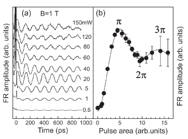
is an effective pulse area. It follows from Eqs. (28) and (25), that electron spin excited by a single pulse depends periodically on the pulse area , i.e. on the field amplitude in the pulse. The power dependence of the electron spin should also have an oscillatory character typical for two level systems (Rabi effect) ll3_eng : strong enough pulse does not merely transfer the system from the ground to the excited state, but can also transfer it from the excited state to the ground one. It is demonstrated in Fig. 7, where the spin beats signals and their amplitudes measured in the InGaAs/GaAs quantum dot arrays are shown as function of the pump pulse power.
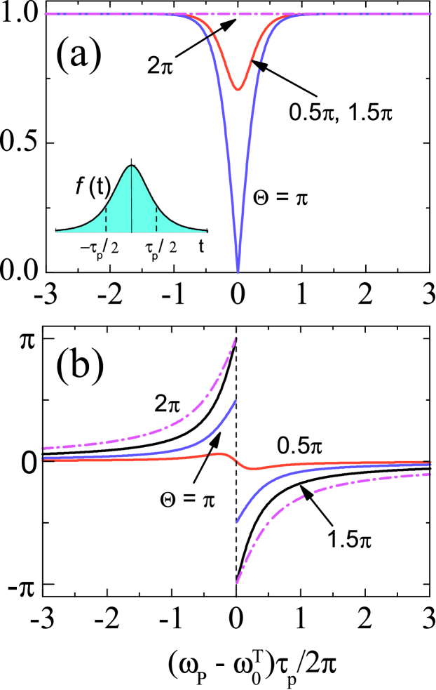
To conclude this Subsection we discuss briefly the dependence of quantities and on the detuned pulse parameters. The detailed analysis is given in Ref. yugova09 , here we just dwell on the case of the Rosen & Zener pulse PhysRev.40.502 :
| (30) |
where the coefficient characterizes the amplitude of the field in the maximum of the pulse. The effective pulse area is . Solution of Eq. (23) for this pulse can be expressed following Ref. PhysRev.40.502 , via hypergeometric function
| (31) |
where the dimensionless detuning from the resonance is . Explicit expressions for and are given in Ref. yugova09 , their dependence on the detuning for different areas is shown in Fig. 8. It is seen from the Figure that for relatively large detunings, , value of is close to , while tends to . Therefore, detuned pulses do not affect the quantum dot state. At , function has a sharp dip at . Such a pulse makes in plane spin components and zero, and results in the most efficient spin component generation.
III.2 Electron spin control by short optical pulses
As follows from Eqs. (25), the circularly polarized pulse does not only generate spin polarization in the quantum dot, but transforms also the spin, which is already present in the system. For example, pulses with erase completely the electron spin components in the structure plane, it results in the electron spin alignment along axis. On the contrary, detuned pulses with accomplish the spin rotation in the structure plane by the angle . Physically, the spin rotation by the circularly polarized pulse can be interpreted as an inverse Faraday effect PhysRev.143.574 : circularly polarized pulse induces the splitting of electron spin sublevels with spin projections onto axis. This splitting is equivalent to an effective magnetic field directed along axis and results in the spin components rotation in the plane.
In that way, there is a possibility to control electron spins by short optical pulses economou:205415 . Corresponding experiments are carried out in the three pulse method: first pulse orients resident electrons by spin, second one serves to control spins and the third pulse is used for the spin polarization detection. Experimentally spin rotation by polarized pulses was demonstrated in Refs. phelps:237402 and Carter:07 for CdTe and GaAs quantum well structures, respectively, and for GaAs quantum dot structures Bonadeo20111998 ; J.Berezovsky04182008 ; Greilich2009 ; Kim2011 . A detailed analysis of the spin polarization control mechanisms is presented in Refs. economou:205415 ; Takagahara:10 , while the experimental achievements are reviewed in Ref. Ramsay . The processes of optical magnetization control in magnetic media have also attracted a considerable interest in recent years PhysRevLett.98.047403 ; PhysRevLett.103.117201 .
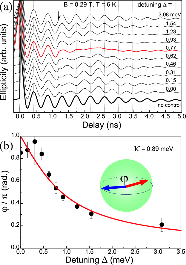
Spin ellipticity signals measured on InGaAs/GaAs quantum dot array in Ref. Greilich2009 by means of the three pulse method: pump-control-probe, as functions of time delay between the pump and probe pulses are shown in Fig. 9(a). The time moment of the circularly polarized control pulse arrival is marked by the arrow, it corresponds to the situation where the electron spin lies in plane, and different curves correspond to different spectral detunings between the control pulse and pump pulse. Control pulse power is adjusted in such a way that its area is close to . It is clearly seen that the spin beats amplitude changes after the control pulse arrival. It corresponds to the spin rotation in the plane around axis, as shown schematically in the inset to Fig. 9(b). Figure 9(b) presents the dependence of the spin rotation angle in the structure plane, measured in the units of , on the detuning between the carrier frequency of the pulse and the trion resonance frequency in quantum dots. Points show the experimental data obtained from the spin beats analysis presented in Fug, 9(a), the solid curve is the theoretical calculation in the framework of the model developed in Ref. economou:205415 . Qualitatively the spin rotation angle dependence is in the agreement with the dependence of on the detuning presented in Fig. 8(b).
It is quite unexpected that for the experimental configuration in question a linearly polarized control pulse makes any effect. Indeed, in accordance with the electron spin coherence generation model described in Sec. II.1, the spin coherence formation requires the spin-dependent photogeneration of trions. Therefore, linearly polarized pump pulse does not lead to a spin coherence generation and to rise of the spin signals in the pump-probe method. However, experiments carried out in Ref. zhukov10 at CdTe/Cd0.78Mg0.22Te quantum well structures demonstrate that the linearly polarized control pulse can significantly suppress the spin beats. It is shown in Fig. 10(a), where the Kerr rotation signals measured in the absence of the control pulse (thick solid curve) and the signals obtained for different time moments of the control pulse arrival are presented. The dependence of the spin Kerr signal on the linearly polarized control pulse power is shown in the inset to Fig. 10(a) and by triangles in Fig. 10(b). It is seen from the Figure that the signal amplitude drops practically to zero for the control pulse powers on the order of W/cm2.
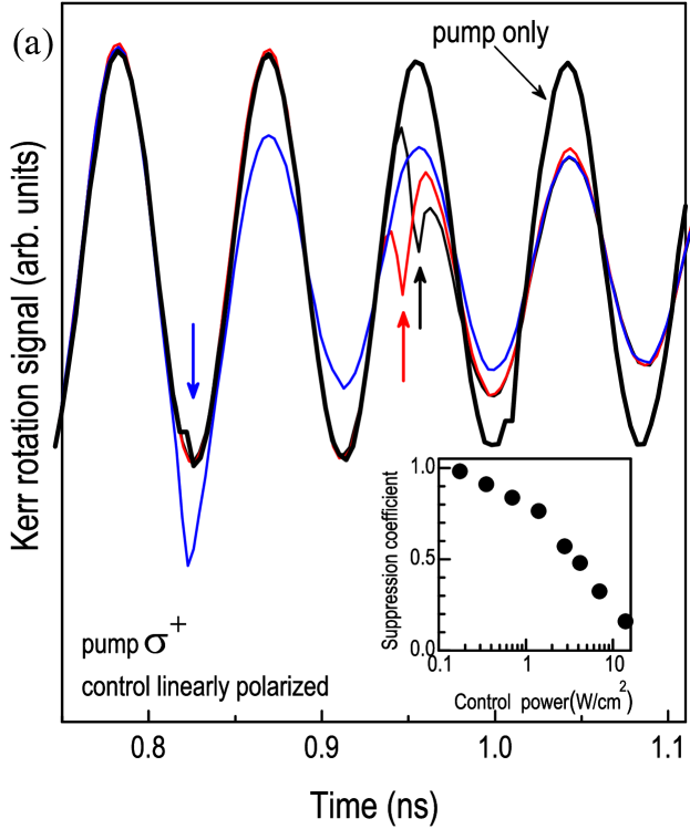
Qualitatively, the spin polarization suppression effect has a simple explanation. Let be the number of ‘‘spin-up’’ electrons and be the number of ‘‘spin-down’’ electrons by the moment of the control pulse arrival. We represent the linearly polarized pulse as a superposition of two circularly polarized ones. Since the trion transition oscillator strength is proportional to the number of electrons with a given spin projection, then, due to the component of the control pulse, trions are formed, while one results in the trion formation, where is a constant proportional to the pulse power. In the simplest model where the hole-in-trion spin relaxation goes faster than the trion recombination, all electrons returned from the trions are depolarized. Therefore, component of electron spin changes by
| (32) |
where denotes the spin component before the control pulse arrival. Equation (32) describes the total spin suppression in the system.
Quantitative description of this effect can be carried out within the framework of the equation system (20), (21). Calculation shows that the spin after the control pulse arrival, , and spin before the pulse arrival, , are linked by a simple relation zhukov10
| (33) |
Here is a constant defined according to Eq. (24) for circular components of the control pulse. It is important to note that the suppression of spin is independent of the control pulse time moment arrival in agreement with experimental data shown in Fig. 10(a).
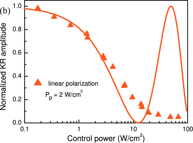
Experimental (triangles) and theoretical (line) dependence of the spin Kerr signal are shown in Fig. 10(b). The details of the experimental data fitting are given in Ref. zhukov10 . There is a good agreement of experiment and theory for moderate control pulse powers. Oscillatory character of the theoretical dependence of the spin coherence suppression efficiency is related with the Rabi effect, which was briefly discussed above at the analysis of the spin coherence excitation. The absence of the oscillations in the experiment is related with the fact that the two level model can provide incorrect description of the trion excitation processes in quantum well structures zhukov10 .
III.3 Microscopic description of probing processes
The two level model which we put forward above to describe electron spin polarization excitation and control can be easily extended to describe the spin probing of electrons and trions.
We decompose a probe pulse whose electric field oscillates along axis into a superposition of two circularly polarized ones. In the first order in the probe pulse amplitude the corrections to the quantum dot wave function can be written as
| (34) |
| (35) |
It is assumed that the electric field in a probe pulse has the form , where is the probe pulse carrier frequency. Before the probe pulse arrival, the quantum dot state is described by the wave function Eq. (18). In this case, generally, both electron and trion states have nonzero occupations: and , respectively, the spin polarization of the electron and trion can also be present: and . It can be shown that the probe pulse induced components of dielectric polarization in the quantum dot have the form yugova09
| (36) | |||
It follows from Eqs. (36) that the induced polarization in the quantum dot has two components. One of those, , is parallel to the polarization plane of the probe pulse, and its value is proportional to the difference of the electron and trion states populations, . Another component, , is orthogonal to the probe pulse polarization plane, and its magnitude is determined by the difference of electron and trion spin projections onto the axis, . It is the component which is responsible for the probe pulse polarization plane rotation as well as the appearance of its ellipticity.
Solution of Maxwell equations for the quantum dot array, whose dielectric polarization is described by Eqs. (36), allows us to determine the magnitudes of the Faraday rotation and ellipticity signals. In the case of a planar array where the typical distances between the dots are small as compared with the wavelength we have yugova09
| (37) |
where is the two-dimensional density of the dots in the array, is the wave vector of light in the system ( is the background dielectric constant assumed to be the same both for dots and matrix), is the trion radiative lifetime:
| (38) |
Kerr rotation signal is determined by the interference of the probe pulse reflected from the structure cap layer and from the quantum dot array. It is described by a standard expression [cf. Eq. (9)]
| (39) |
where is the reflection coefficient at the air/cap layer boundary, and are the transmission coefficients of this boundary inside and outside, respectively. The effect of the cap layer on the Faraday and ellipticity effects can be taken into account by a factor in the right hand side of Eq. (37).

As it follows from Eqs. (37) and (39), the spin signals amplitudes are determined by the difference of the spin components of trion and electron in a quantum dot. To analyze the frequency dependence of the Faraday rotation and ellipticity signals, we represent the probe pulse field as , where is the probe pulse envelope function. One can check that
| (40) |
where
| (41) |
and . In the particular case of the Rosen & Zener pulse, where , we obtain
| (42) |
where is the generalized Riemann -function.
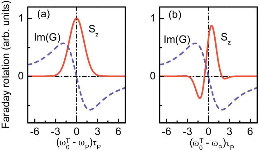
Figure 11 shows real and imaginary parts of the function calculated for the Rosen & Zener pulse. Qualitatively, the behavior of Faraday rotation and ellipticity as functions of detuning between the trion resonance and the probe pulse carrier frequency are analogous to those obtained in Sec. II.2, see Fig. 4. It is worth to note, that the maximum sensitivity of Faraday rotation and ellipticity signals corresponds to different detunings: Faraday rotation signal takes its maximum value for detuned pulses , while ellipticity takes its maximum for the resonant ones. We shall ascertain below that this leads to different dependence of the spin signals on the pump-probe pulses delay in inhomogeneous quantum dot ensembles.
IV Temporal dependence of the spin Faraday, Kerr and induced ellipticity signals
We discussed in Secs. II and III the mechanisms of the spin signals formation in the pump-probe method, the dependence of the signal amplitudes on the pump power and on spectral positions of pump and probe pulses, as well as the possibilities to control the spin polarization by means of optical pulses. Below we focus on the analysis of the Faraday rotation and ellipticity signals dependence on the time delay between pump and probe pulses.
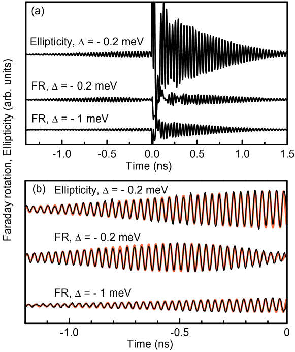
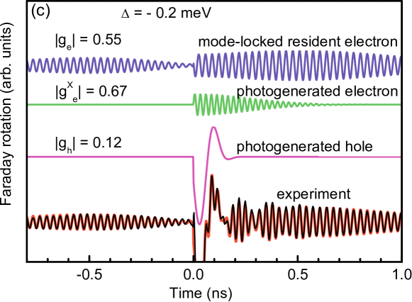
Figure 12(a) shows typical spin signals of Faraday rotation and ellipticity obtained in Ref. glazov2010a on the -type InGaAs quantum dot array. The measurements were carried out in the so-called ‘‘two color’’ (nondegenerate) pump-probe technique, where the pump and probe pulses are generated by different lasers, hence their carrier frequencies can be tuned independently. The pulses themselves are synchronized with high precision (about 10 fs). Pumping and probing is carried out by a periodic sequence of the pulses following with a repetition period ns.
Key experimental observations are the following:
-
1.
Signals at positive delays have a complex character corresponding to the superposition of oscillations with different frequencies. Analysis of the oscillation frequencies and decay times (Fig. 12(c)) allows one to establish that the observed signal is a superposition of the resident electron spin signal, as well as photocreated (in neutral dots) electron and hole signals glazov2010a ; yu07 .
-
2.
The remarkable signals take place also at negative delays, that is when the probe pulse arrives before the next pump pulse. Effects of spin signals generation at negative delays and spin accumulation at the excitation of quantum wells and quantum dots by a periodic sequence of the pulses are described below in Secs. IV.1, IV.2.
-
3.
Under the conditions of spectral degeneracy of pump and probe pulses, the amplitude of the Faraday rotation signal induced by resident electrons behaves nonmonotonically as a function of delay: at small delays the signal amplitude builds up, afterwards it decays. It is clearly seen in Fig. 12(b), middle curve, there the area of negative delays is shown. Ellipticity signal demonstrates an expected behavior in this case: damped oscillations. Section IV.3 is devoted to the buildup of the Faraday rotation.
IV.1 Resonant spin amplification and spin precession mode-locking
As we have already noted above, the spin signals at negative delays arise due to the fact, that electron spin does not fully relax during the pulse repetition period. Depending on the relation between the electron spin precession period and the pump pulse repetition period, the spin polarization in the system can either accumulate or get suppressed.
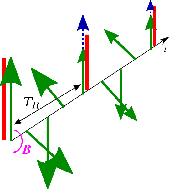
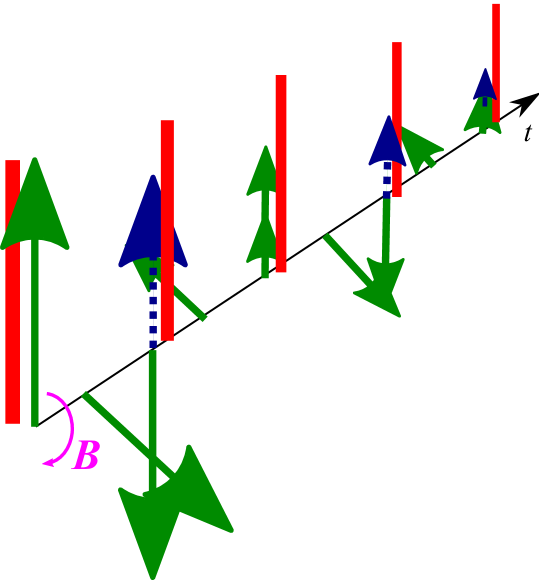
Indeed, as it is shown in Fig. 13, if the pump pulse repetition period, , is a multiple of the electron spin precession period in the external field ,
| (43) |
then the next pump pulse adds the spin in phase with the precessing one. In this case, the spin polarization in the system is enhanced as compared with that formed by a single pulse. This effect is known as resonant spin amplification. If condition (43) is not fulfilled, the phase synchronization fails and spin polarization is suppressed.
In experiments the spin dynamics of electron ensemble is studied, as a rule. Optical excitation of the quantum dot array or the quantum well results in the spin polarization of the charge carriers with different energies being spread within the pump pulse spectral width . Electron -factor values are different, so the electron spin precession frequencies are different. An additional contribution to the spread of spin precession frequencies is given by the hyperfine interaction of electron spins with the spins of lattice nuclei. Spin beats damping is characterized by the following parameters: being the transverse to the external field electron spin components relaxation time, being the dephasing time of electron spin in the ensemble contributed both by the relaxation processes and the spread of Larmor precession frequencies, the latter one is characterized by the time , where is the spin precession frequency spread. The specifics of spin dynamics under the excitation by a periodic train of the pulses is determined by the repetition period of the pulses and the spin beats decay times. Obviously, if , the effects of spin polarization accumulation are unessential, since spin relaxes before the next pulse arrival. Below we assume that and analyze two important cases: (i) of weak dephasing related with the spin precession frequency spread , where the resonant spin amplification is realized, and (ii) the regime of strong dephasing, , where the spin precession mode-locking becomes possible.
IV.1.1 Resonant spin amplification
We start with a situation where the spread of the spin precession frequencies is not relevant and the spin beats damping is determined by the spin relaxation processes. We assume for simplicity that the average electron spin is small (both generated by a single pump pulse and accumulated by a pump pulse train). Therefore, we obtain from Eq. (1) for the periodic sequence consisting of large enough number of pulses:
| (44) |
Here is the electron spin created by a single pulse, is the delay between the probe pulse and the nearest next pump pulse, it can take any negative value in the interval . It is assumed in derivation of Eq. (44) that .
Calculation Kikkawa98 ; beschoten shows that
| (45) |
It follows from Eq. (45) that the electron spin dependence on the Larmor precession frequency (and, correspondingly, on the magnetic field) at a fixed delay consists of a sequence of maxima corresponding to the condition , where is an integer. In the vicinity of the maximum where and , expression (45) can be rewritten in the form of Lorentz function
| (46) |
In this approximation the peak width is determined by the quantity
| (47) |
which, in the limit of long spin relaxation times, , passes to , and the width is the smaller the longer spin relaxation time .
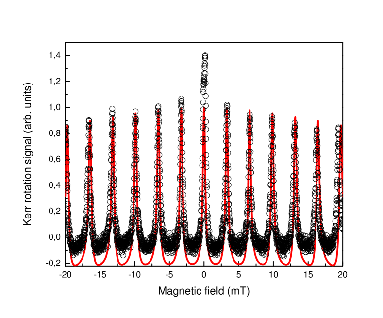
Figure 14 presents the resonant spin amplification spectrum: the dependence of the Kerr rotation signal, , on the magnetic field obtained at CdTe/Cd0.78Mg0.22Te quantum well structure at small negative delay ast08 . Peaks correspond to the commensurability condition of the spin precession period and the pulse repetition period, Eq. (43). Note, that the zero field peak is larger than adjacent ones, seemingly, it is related with the influence of nuclear effects on the electron spin. Peak height decreases monotonously with its number and the peaks themselves become slightly broadened. It is caused by the -factor spread in the localized electron ensemble, which gives rise to an additional spin dephasing. The experimental data fitting with allowance for the -factor values spread carried out by using theoretical formulae obtained in Ref. glazov08a , see also ast08 and shown by a solid line in Fig. 14, describes experiment rather well. The comparison of the theoretical calculation and the experimental data allows us to establish the main parameters of the resident electrons spin kinetics ast08 : mean -factor value, , its spread (this spread was modelled by a Gaussian distribution in our theory), transverse spin relaxation time ns. These parameters obtained by means of resonant spin amplification technique agree well with the values extracted from the Hanle effect and temporal dependence of the spin signals on the same structure.
Classical expression for the resonant spin amplification spectrum Eq. (45) can be easily extended to allow for the arbitrary spin relaxation anisotropy glazov08a inherent to semiconductor quantum well structures. As compared with the isotropic spin relaxation case, the maxima at do not change, while the zero field maximum can be either suppressed (if spin component relaxation time is shorter than that of the in plane spin components) or enhanced (if spin component turns out to be longer living one). Spin relaxation anisotropy was discovered by Hanle effect measurements in Ref. averkiev06 and by Kerr signal spin beats in magnetic field larionov:033302 ; larionov11:eng . The experimental studies of the spin relaxation anisotropy in the resonant spin amplification technique are impeded since the peak at is strongly affected by the hyperfine interaction of electron and nuclear spins.
An additional specifics of the resonant spin amplification spectra can be brought about by the hole-in-trion (in -type structures) and by the electron-in-tron (in -type structures) spin dynamics. If trion spin relaxation is suppressed, then the considerable spin polarization of resident charge carriers appears in magnetic field only, as discussed above in Sec. II.1.1. At that, the resonant spin amplification peak amplitude increases with an increase of the peak number in moderate magnetic fields and the spectrum envelop has a smooth bat-like shape. One can manage to extract the spin relaxation times of unpaired charge carrier in the trion from such spectra sokolova09 ; fokina-2010 ; korn_njp .
Equation (45) does not account for the spin polarization saturation at the periodic pumping. The corresponding extension of the treatment in the framework of the two level model describing electron spin excitation by short circularly polarized pulses outlined in Sec. III.1 was carried out in Refs. yugova09 ; sokolova09 ; fokina-2010 . With an increase of the pumping the peaks become broader and the spin polarization dependence on magnetic field becomes smoother.
IV.1.2 Spin precession mode-locking
Let us turn now to the opposite limiting case where the spread of electron -factors and the random nuclear fields result in fast electron spin dephasing, i.e.
| (48) |
In this situation prima facie any remarkable spin signals at negative delays can not be expected, because electron spin gets dephased before the next pulse arrival.
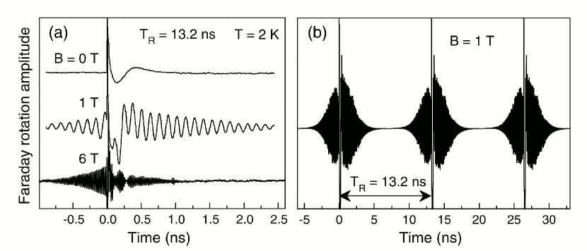
However, as mentioned above, the spin of a given electron is conserved during long time which exceeds by far the pulse repetition period. Moreover, if condition Eq. (48) holds, the wide spectrum of spin precession frequencies is excited. Hence, there are the spins in the whole ensemble of the precessing ones for which the spin precession and the pump pulse repetition frequencies are synchronized. Obviously, the spins of these electrons will always be in phase at the time moments , i.e. when the next pump pulse arrives. The spins of remaining charge carriers in these time moments have random precession phases, and they do not contribute to the observed signal. Therefore, if condition Eq. (48) is satisfied, the spin signal decays during the time scale on the order of , and afterwards emerges by the next pump pulse arrival during approximately the same time. This effect was observed in the pump-probe experiments on InGaAs quantum dot arrays A.Greilich07212006 and was named spin precession mode-locking. Typical behavior of the Faraday rotation signal as function of the time delay between the pump and probe pulses, measured on the InGaAs/GaAs quantum dot sample, are presented in Fig. 15.
The spin precession mode-locking phenomenon allows one, in certain extent, to overcome the electron spin dephasing effects related with an inhomogeneity of the electron ensemble. About a electron spins precess with commensurable frequencies under the conditions of experiment, Ref. A.Greilich07212006 . Since the spread of spin precession frequencies decreases with the magnetic field decrease, at small fields the situation where one or two spin precession modes are excited can be achieved, as shown experimentally in Ref. greilich09 . Application of spin precession mode-locking allowed one to determine experimentally the transverse relaxation time of electron spin, , and to excite the spin echo under the pumping by a sequence containing pairs of circularly polarized pulses A.Greilich07212006 .
Evidently, the ratio of the long living (electron) spin signal amplitudes at negative and positive delays must be determined by the fraction of electrons, whose spins satisfy the mode-locking condition, Eq. (43). Indeed, the contribution to the signal at negative delays is given by only those electrons, whose spin precession is synchronous with the pump pulses, while at positive delays all electrons from the ensemble contribute to the signal. Analysis shows that this ratio should not exceed . It is seen from the experimental data shown in Fig. 15 that it is not the case: is just slightly smaller than . It means, that synchronization condition (43) is satisfied in almost all the dots. The reason for this is described in the next Section.
IV.2 Electron spin precession frequency focusing provided by interaction with lattice nuclei
Up to this point we excluded from consideration the nuclear spin subsystem. Indeed, during the time interval of about ten nanoseconds which corresponds to the repetition period of the pulses, nuclear spins may be considered frozen. Owing to hyperfine interaction, nuclear spin fluctuations contribute to the spread of electron spin precession frequencies and result in the electron spin dephasing PhysRevB.64.125316 ; merkulov02 ; PhysRevLett.88.186802 ; PhysRevB.66.161318 , since electron spin precession frequency is determined by the total magnetic field, including both the external field and Overhauser field, acting from the side of nuclei. For instance, in the box model, where the hyperfine interaction constant of electron with nuclei is the same for all quantum dot nuclei Kozlov2007 ,
where is the total nuclear spin ( are mean values of the nuclear spin vectors, enumerates nuclei interacting with the electron). If nuclei are on average unpolarized, vectors in different dots are oriented randomly, and frequency fluctuates from the dot to the dot. However, in the pump-probe experiments optical excitation takes place by the long train of circularly polarized pulses, and nuclear spin polarization may change, both due to the interaction with an external field and with electron spin. In the pump-probe regime, it leads to an unconventional dynamics of electron and nuclear spins A.Greilich09282007 .
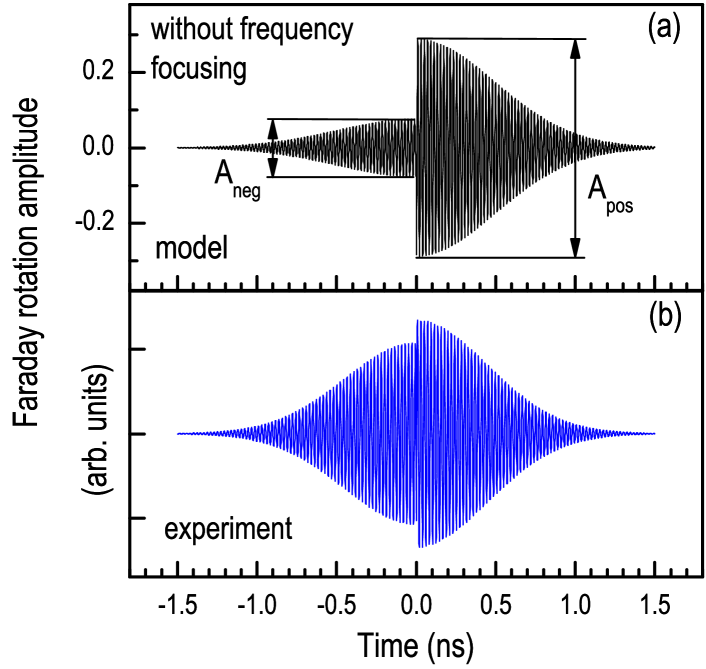
Figure 16 shows calculated (a) and measured (b) spin Faraday signals in the InGaAs quantum dot array A.Greilich09282007 . Figures shows dramatic difference of signal amplitudes at negative delays in the experiment and in the calculation which does not take into account nuclear effects. The conclusion was drawn in Ref. A.Greilich09282007 that it is the interaction of electrons with nuclear spins being responsible for the observed effect: in the process of electron spin coherence excitation by the periodic pulse train nuclear spins orient in such a way, that the electron spin precession period becomes a divisor of the pump pulse repetition period.
There are two theoretical approaches aimed at the description of the frequency focusing process. In the model suggested in Ref. A.Greilich09282007 , see also Ref. carter:167403 , the random nuclear spin flips are considered, which are caused by the hyperfine interaction. The rate of these processes can be estimated as dp74 ; A.Greilich09282007
| (49) |
where is the electron spin correlation time in the quantum dot. The key assumption of this approach is that the electron spin correlation time is governed by the processes of the pump pulse interaction with the quantum dot, therefore an estimate holds A.Greilich09282007 :
| (50) |
Here is the trion formation probability by a single pump pulse. In those dots where the phase synchronization condition with allowance for the nuclear field is fulfilled:
| (51) |
by the moment of the next pump pulse arrival , and the trion is not formed. Therefore, , correlation time , and nuclear spin flips stop. In those dots where the spin precession phase synchronization condition is not fulfilled, nuclear spin flips take place until changes in random manner in such a way that the condition Eq. (51) is reached. Similar effects were discussed also in Ref. 2010arXiv1006.5144K .
Alternative approach to the nuclei induced electron spin precession frequency focusing is suggested in Ref. yugova11 . The description of the coupled dynamics of electron and nuclear spins is carried out within a classical model, where the electron spin, , and nuclear spin fluctuation, , are treated as classical vectors, which precess around the external field and around each other. The analysis of the spin dynamics equations shows that the nuclear spin precession in the external magnetic field with the frequency results, owing to the hyperfine interaction, in additional small oscillations of electron spin with this very frequency. These electron spin oscillations, in turn, affect the nuclear spin dynamics, in fact, they cause nuclear magnetic resonance. As a result, the projection of nuclear spin onto the external magnetic field, , start to vary slowly, until the electron spin precession frequency satisfies the mode-locking condition Eq. (51). This process is no more random and its rate can be estimated as yugova11
| (52) |
The rate of such a process is, by factor , larger than that of the nuclear spin flips in the model of random flips, Eq. (49). Estimations by Eq. (52) show that in experimental conditions A.Greilich09282007 the nuclei spin focusing time ranges from units to tens of seconds, which is in the satisfactory agreement with the experimental data. For detailed description of the coupled dynamics of electron and nuclear spins under the pump-probe conditions further experimental studies are needed, in particular, the analysis of the focusing time as function of the magnetic field and pump pulse power.
IV.3 Buildup of Faraday rotation signal
So far, we established the origins of the spin signals at negative delays between the pump and probe pulses, shown in Fig. 12. Let us turn now to the discussion of the last bright experimental fact: the amplitude of the Faraday rotation signal, related with the resident electron (top curve in Fig. 12(c)) increases with time before decaying. It is especially remarkable at negative delays: with an increase of spin beats amplitude first increases, and decreases afterwards. It is evident, that nuclear effects can not determine such a behavior: firstly, the buildup of Faraday rotation signal goes fast, approximately during ns, and, secondly, the ellipticity signal behavior is quite standard, the oscillation amplitude decays with time. Therefore, nonmonotonic behavior of the Faraday signal amplitude can be related only with the specifics of this signal spectral sensitivity.
In order to describe this effect qualitatively and quantitatively, we note that electron -factor depends on the localization energy of this charge carrier. Indeed, the renormalization of the -factor in direct band semiconductors is determined mostly by the admixture of the valence band states to the conduction band states PhysRev.114.90 ; ivchenko_kiselev92:eng ; ivchenko05a . Since trion excitation energy is related with the electron localization energy, the resident carrier -factor in a quantum dot is coupled with the optical transition frequency . This dependence can be quite accurately described by a linear function A.Greilich07212006 ; PhysRevB.75.245302 :
| (53) |
where and are some parameters dependent on the quantum dot ensemble material.
The pump pulse excites out of a broad distribution of quantum dots over energy an ensemble, whose spectral width amounts to meV for pulses with duration ps. We introduce a function , which describes the magnitude of the electron spin component in the quantum dot with the resonant frequency and spin precession frequency right after the pump pulse arrival with the carrier frequency . Note, that the Larmor frequency in a quantum dot is determined, in general, not only the -factor value Eq. (53), but also the nuclear spin polarization fluctuation. Spin ellipticity and Faraday rotation signals detected by a probe pulse with the carrier frequency are given (up to a common factor) in accordance with Eq. (40) by the expression yugova09 ; glazov2010a :
| (54) |
Here the delay between the pump and probe pulse , function is the joint distribution of optical and Larmor frequencies in quantum dots (in the absence of nuclear fluctuations ), and describes spectral sensitivity of the signals, see Eq. (41). Last two factors in Eq. (54) describe the single spin dynamics in the quantum dot, is the spin relaxation time and is the initial phase of the spin precession. Functions and can be found from the general solution of spin dynamics equations, given in Ref. yugova09 .
The detailed analysis and modeling of electron spin dynamics in quantum dots described by Eq. (54) is carried out in Ref. glazov2010a . Here we consider a simplest model, which allows us to obtain qualitative description of the situation. Let us take that has the form
| (55) |
At moderate values of detunings, , between the probe carrier frequency and resonance frequency of the quantum dot, , function given by Eq. (55) has a shape similar to that for Rosen & Zener pulse [see Eq. (42)]. At the imaginary part of (that is Faraday rotation signal sensitivity) decays faster than the exact function, which behaves as . It results only in quantitative difference of the Faraday signal behavior calculated in this model and obtained in the exact calculation glazov2010a . We assume further, that nuclear effects are absent and spin precession frequency is stringently linked with the quantum dot resonance frequency . Moreover, we choose function in the form
| (56) |
where is some constant which depends on the pump pulse area and we set , . The effects related with the spin precession mode-locking are discussed below.
Integration in Eq. (54) gives
| (57a) | |||
| (57b) |
Here the following notations are introduced: , is the pump and probe pulses detuning, is the observed spin precession frequency, and .
It is seen from Eqs. (57) that the temporal dependence of Faraday rotation and ellipticity signals can be qualitatively different. The ellipticity signal amplitude simply decays with time, this decay rate is determined by the spread of Larmor frequencies of ‘‘excited’’ electrons. Faraday signal has two contributions [see Eq. (57b)]: first one is similar to the ellipticity, but its amplitude depends sharply on the detuning, , white the amplitude of the second contribution () contains the linear in time factor. For degenerate pump and probe pulses () Faraday signal, described by the second term in brackets of Eq. (57b), first grows and afterwards decay, in agreement with experimental data, presented in Fig. 12.
Such a temporal behavior of spin signals is related with the different spectral sensitivity of the Faraday and ellipticity signals, and it is a direct consequence of the correlation between the Larmor frequency and optical transition frequency in a quantum dot, Eq. (53). Figure 17 illustrates the spin Faraday signal formation under the conditions of degenerate pump and probe pulses. At the spin distribution is a symmetric function of and it makes no contribution to the Faraday signal, since it is determined by the convolution of and odd function , as shown in Fig. 17(a). The spin distribution becomes asymmetric with a course of time, since [for , in Eq. (53)] spins in quantum dots with larger optical transition energies, , precess faster than those in dots with smaller transition energies. Therefore, with an increase of the pump and probe pulses temporal separation, the spin distribution function becomes asymmetric with respect to the carrier frequency of the optical pulse, as shown in Fig. 17(b). Therefore, Faraday rotation signal becomes nonzero at . At large enough delays electron spin dephases and Faraday rotation decays.
Note, that the detuning between the probe and pump pulses already introduces asymmetry into the spin distribution with respect to the probe pulse carrier frequency, , and results in the Faraday signal formation even at . Therefore, at the decaying with time component of the spin Faraday signal appears, which is described by the first term in brackets of Eq. (57b). The ellipticity spectral sensitivity, , is even, therefore ellipticity signal reflects ensemble average spin component. Induced ellipticity decays as a function of time due to the spread of the Larmor frequencies. It is in the agreement with the experimental data shown in Fig. 12.
The model suggested qualitatively describes also the differences between the Faraday rotation and ellipticity at negative delays. In the spin precession mode-locking regime, considered in Sec. IV.1.2, the distribution function of spin component, , has sharp maxima for those quantum dots, where . If one allows for the synchronized modes only, the spin signals become even functions of the pump-probe delay, . It implies, that the Faraday signal at the zero detuning and first builds-up and afterwards decays with an increase of , see Fig. 12(b). Presence of other spin precession frequencies gives rise to the additional contribution to the signal, which decays at and which is absent at negative delays. Note, that the focusing of electron spin precession frequency induced by the electron interaction with the lattice nuclei breaks the correlation between optical transition and spin precession frequencies and weakens the growing part of Faraday signal.
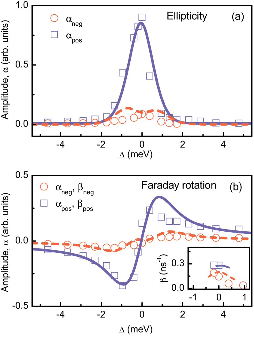
The simple model outlined here is not free of drawbacks: due to simplified form of the function Eq. (55), it does not describe the amplitudes of Faraday signal at large detunings. For the same reasons, the spectral dependence of -factor, extracted from the Faraday rotation experiment is different from the predicted by Eq. (57b). The complete description of experimental data shown in Fig. 12, was carried out in Ref. glazov2010a . Microscopic calculation by using exact function and functions , , obtained with allowance for the spin precession mode-locking, are in good agreement with experiment. Comparison of the theory and experiment is presented in Fig. 18. Figure shows spectral dependence of the amplitudes of induced ellipticity [panel (a)] and Faraday rotation [panel (b)]. Circles and squares are the experimental data obtained at negative and positive delays, respectively, by means of experimental data fitting using the formula:
Curves in Fig. 18 are the result of the calculation. Figure shows amplitudes, , of the Faraday and ellipticity signals decaying components. The inset to panel (b) shows amplitudes of the growing in time contribution to the Faraday signal, . A good agreement of spectral dependence of signal amplitudes is seen from the Figure.
Thus, spin Faraday and ellipticity signals in inhomogeneous arrays of quantum dots are formed by different resident electron ensembles. As a result, their behavior as function of the pump and probe pulses delay can be qualitatively different. It is most brightly manifested in the buildup of the Faraday rotation signal as a function of time, being a result of the link between the electron -factor and optical transition energy in quantum dot.
V Conclusion
In this review, the electron, exciton and trion spin dynamics in semiconductor nanostructures observed by the pump-probe method is examined. The main physical mechanisms of resident electron spin orientation at excitation of excitons and trions by circularly polarized light pulses are established, the principles of charge carriers spin coherence detection by linearly polarized optical pulses are considered. The possibilities to control spins by light pulses of different polarization are analyzed.
Two approaches to describe electron spins interaction with optical pulses are suggested. One of those is macroscopic, it is based on the consideration of electron and electron-hole complexes ensemble. In the other, microscopic, approach, the single electron interaction with the optical pulse is treated within a two level model.
We have demonstrated the electron spin dynamics specifics in quantum well and quantum dot structures under excitation of spins by a periodic train of pulses. The spin precession mode-locking and the focusing of electron spin precession frequencies by means of charge carrier interaction with lattice nuclei are examined. It is shown that the different spin signals in the pump-probe method: Faraday and Kerr rotation, as well as induced ellipticity are sensitive to the spin dynamics in different electron ensembles. It may result in the different temporal behavior of spin Faraday and ellipticity signals, this fact should be taken into account at extraction of electron and hole spin dynamics parameters from experimental data.
The applications of spin Faraday and Kerr signals for studies of nuclear spin dynamics in semiconductors and semiconductor nanostructures as well as for studies of spin-dependent processes in semiconductor microcavities may serve as prospective directions for the development of the pump-probe method.
Author is grateful to M. Bayer, M.R. Vladimirova, E.L. Ivchenko, T. Korn, Al.L. Efros, I.A. Yugova, and D.R. Yakovlev for help and useful discussions. This work was partially supported by the grants of RFBR, Dynasty Foundation – ICFPM, and EU projects: SpinOptronics and POLAPHEN.
References
- (1) G. Lampel. Nuclear Dynamic Polarization by Optical Electronic Saturation and Optical Pumping in Semiconductors. Phys. Rev. Lett. 20, 491 (1968).
- (2) Optical orientation/ Eds. F. Meier and B. P. Zakharchenya, North-Holland, Amsterdam (1984).
- (3) D. D. Awschalom, J. M. Halbout, S. von Molnar, T. Siegrist, F. Holtzberg. Dynamic Spin Organization in Dilute Magnetic Systems. Phys. Rev. Lett. 55, 1128 (1985).
- (4) N. I. Zheludev, M. A. Brummell, R. T. Harley, A. Malinowski, S. V. Popov, D. E. Ashenford, B. Lunn. Giant specular inverse Faraday effect in . Solid State Communications 89, 823 (1994).
- (5) J. M. Kikkawa, D. D. Awschalom. Resonant Spin Amplification in -Type GaAs. Phys. Rev. Lett. 80, 4313 (1998).
- (6) J. M. Kikkawa, I. P. Smorchkova, N. Samarth, D. D. Awschalom. Room-Temperature Spin Memory in Two-Dimensional Electron Gases. Science 277, 1284 (1997).
- (7) A. Greilich, D. R. Yakovlev, A. Shabaev, A. L. Efros, I. A. Yugova, R. Oulton, V. Stavarache, D. Reuter, A. Wieck, M. Bayer. Mode Locking of Electron Spin Coherences in Singly Charged Quantum Dots. Science 313, 341 (2006).
- (8) M. A. Brand, A. Malinowski, O. Z. Karimov, P. A. Marsden, R. T. Harley, A. J. Shields, D. Sanvitto, D. A. Ritchie, M. Y. Simmons. Precession and Motional Slowing of Spin Evolution in a High Mobility Two-Dimensional Electron Gas. Phys. Rev. Lett. 89, 236601 (2002).
- (9) W. J. H. Leyland, G. H. John, R. T. Harley, M. M. Glazov, E. L. Ivchenko, D. A. Ritchie, I. Farrer, A. J. Shields, M. Henini. Enhanced spin-relaxation time due to electron-electron scattering in semiconductor quantum wells. Phys. Rev. B 75, 165309 (2007).
- (10) M. Griesbeck, M. M. Glazov, T. Korn, E. Y. Sherman, D. Waller, C. Reichl, D. Schuh, W. Wegscheider, C. Schüller. Cyclotron effect on coherent spin precession of two-dimensional electrons. Phys. Rev. B 80, 241314 (2009).
- (11) J. M. Kikkawa, D. D. Awschalom. Lateral drag of spin coherence in gallium arsenide. Nature 397, 139 (1999).
- (12) Y. K. Kato, R. C. Myers, A. C. Gossard, D. D. Awschalom. Observation of the Spin Hall Effect in Semiconductors. Science 306, 1910 (2004).
- (13) S. A. Crooker, D. L. Smith. Imaging Spin Flows in Semiconductors Subject to Electric, Magnetic, and Strain Fields. Phys. Rev. Lett. 94, 236601 (2005).
- (14) D. Awschalom, D. Loss, N. Samarth (eds.). Semiconductor spintronics and quantum computation (Springer: Berlin, New York, 2002).
- (15) M. I. Dyakonov (ed.). Spin Physics in Semiconductors (Springer-Verlag: Berlin, Heidelberg, 2008).
- (16) Y. Kusraev, G. Landwehr (eds.). Semiconductor Science and Technology, Special Issue: Optical Orientation, vol. 23 (IOP Publishing, 2008).
- (17) A. G. Aronov, E. L. Ivchenko. Dichroism and optical anisotropy of media with oriented spins of free electrons. Sov. Phys. Solid State 15, 160 (1973).
- (18) E. A. Zhukov, D. R. Yakovlev, M. M. Glazov, L. Fokina, G. Karczewski, T. Wojtowicz, J. Kossut, M. Bayer. Optical control of electron spin coherence in CdTe/(Cd,Mg)Te quantum wells. Phys. Rev. B 81, 235320 (2010).
- (19) S. O’Leary, H. Wang. Manipulating nonlinear optical responses from spin-polarized electrons in a two-dimensional electron gas via exciton injection. Phys. Rev. B 77, 165309 (2008).
- (20) C. Phelps, T. Sweeney, R. T. Cox, H. Wang. Ultrafast Coherent Electron Spin Flip in a Modulation-Doped CdTe Quantum Well. Phys. Rev. Lett. 102, 237402 (2009).
- (21) A. Greilich, S. E. Economou, S. Spatzek, D. R. Yakovlev, D. Reuter, A. D. Wieck, T. L. Reinecke, M. Bayer. Ultrafast optical rotations of electron spins in quantum dots. Nature Physics 5, 262 (2009).
- (22) D. Yakovlev, M. Bayer. Coherent spin dynamics of carriers, in Spin physics in semiconductors ed. M. Dyakonov, p. 135 (Springer, 2008).
- (23) Z. Chen, S. G. Carter, R. Bratschitsch, S. T. Cundiff. Optical excitation and control of electron spins in semiconductor quantum wells. Physica E 42, 1803 (2010).
- (24) M. H. Mikkelsen, J. Berezovsky, N. G. Stoltz, L. A. Coldren, D. D. Awschalom. Optically detected coherent spin dynamics of a single electron in a quantum dot. Nature Physics 3, 770 (2007).
- (25) M. Atature, J. Dreiser, A. Badolato, A. Imamoglu. Observation of Faraday rotation from a single confined spin. Nature Physics 3, 101 (2007).
- (26) R. I. Dzhioev, B. P. Zakharchenya, V. L. Korenev, M. N. Stepanova. Spin diffusion of optically oriented electrons and photon entrainment in n-gallium arsenide. Physics of the Solid State 39, 1765 (1997).
- (27) L. V. Fokina, I. A. Yugova, D. R. Yakovlev, M. M. Glazov, I. A. Akimov, A. Greilich, D. Reuter, A. D. Wieck, M. Bayer. Spin dynamics of electrons and holes in InGaAs/GaAs quantum wells at millikelvin temperatures. Phys. Rev. B 81, 195304 (2010).
- (28) A. Shabaev, A. L. Efros, D. Gammon, I. A. Merkulov. Optical readout and initialization of an electron spin in a single quantum dot. Phys. Rev. B 68, 201305 (2003).
- (29) J. Tribollet, F. Bernardot, M. Menant, G. Karczewski, C. Testelin, M. Chamarro. Interplay of spin dynamics of trions and two-dimensional electron gas in a -doped CdTe single quantum well. Phys. Rev. B 68, 235316 (2003).
- (30) M. I. Dyakonov, V. I. Perel. Theory of optical spin orientation of electrons and nuclei in semiconductors. in Optical orientation, eds. F. Meier and B. P. Zakharchenya, p. 11 (1984).
- (31) X. Marie, T. Amand, P. Le Jeune, M. Paillard, P. Renucci, L. E. Golub, V. D. Dymnikov, E. L. Ivchenko. Hole spin quantum beats in quantum-well structures. Phys. Rev. B 60, 5811 (1999).
- (32) T. A. Kennedy, A. Shabaev, M. Scheibner, A. L. Efros, A. S. Bracker, D. Gammon. Optical initialization and dynamics of spin in a remotely doped quantum well. Phys. Rev. B 73, 045307 (2006).
- (33) M. V. G. Dutt, J. Cheng, B. Li, X. Xu, X. Li, P. R. Berman, D. G. Steel, A. S. Bracker, D. Gammon, S. E. Economou, R.-B. Liu, L. J. Sham. Stimulated and Spontaneous Optical Generation of Electron Spin Coherence in Charged GaAs Quantum Dots. Phys. Rev. Lett. 94, 227403 (2005).
- (34) E. A. Zhukov, D. R. Yakovlev, M. Bayer, M. M. Glazov, E. L. Ivchenko, G. Karczewski, T. Wojtowicz, J. Kossut. Spin coherence of a two-dimensional electron gas induced by resonant excitation of trions and excitons in CdTe/(Cd,Mg)Te quantum wells. Phys. Rev. B 76, 205310 (2007).
- (35) Z. Chen, R. Bratschitsch, S. G. Carter, S. T. Cundiff, D. R. Yakovlev, G. Karczewski, T. Wojtowicz, J. Kossut. Electron spin polarization through interactions between excitons, trions, and the two-dimensional electron gas. Phys. Rev. B 75, 115320 (2007).
- (36) I. A. Yugova, A. A. Sokolova, D. R. Yakovlev, A. Greilich, D. Reuter, A. D. Wieck, M. Bayer. Long-Term Hole Spin Memory in the Resonantly Amplified Spin Coherence of InGaAs/GaAs Quantum Well Electrons. Phys. Rev. Lett. 102, 167402 (2009).
- (37) G. V. Astakhov, M. M. Glazov, D. R. Yakovlev, E. A. Zhukov, W. Ossau, L. W. Molenkamp, M. Bayer. Time-resolved and continuous-wave optical spin pumping of semiconductor quantum wells. Semiconductor Science and Technology 23, 114001 (2008).
- (38) T. Korn. Time-resolved studies of electron and hole spin dynamics in modulation-doped GaAs/AlGaAs quantum wells. Physics Reports 494, 415 (2010).
- (39) T. Korn, M. Kugler, M. Griesbeck, R. Schulz, A. Wagner, M. Hirmer, C. Gerl, D. Schuh, W. Wegscheider, C. Schueller. Engineering ultralong spin coherence in two-dimensional hole systems at low temperatures. New Journal of Physics 12, 043003 (2010).
- (40) P. Machnikowski, T. Kuhn. Theory of the time-resolved Kerr rotation in ensembles of trapped holes in semiconductor nanostructures. Phys. Rev. B 81, 115306 (2010).
- (41) B. Eble, P. Desfonds, F. Fras, F. Bernardot, C. Testelin, M. Chamarro, A. Miard, A. Lemaître. Hole and trion spin dynamics in quantum dots under excitation by a train of circularly polarized pulses. Phys. Rev. B 81, 045322 (2010).
- (42) R. Dzhioev, B. Zakharchenya, V. Korenev, P. Pak, D. Vinokurov, O. Kovalenkov, I. Tarasov. Optical orientation of donor-bound excitons in nanosized InP/InGaP islands. Physics of the Solid State 40, 1587 (1998).
- (43) S. Cortez, O. Krebs, S. Laurent, M. Senes, X. Marie, P. Voisin, R. Ferreira, G. Bastard, J.-M. Gerrard, T. Amand. Optically Driven Spin Memory in -Doped InAs-GaAs Quantum Dots. Phys. Rev. Lett. 89, 207401 (2002).
- (44) M. Ikezawa, B. Pal, Y. Masumoto, I. V. Ignatiev, S. Y. Verbin, I. Y. Gerlovin. Submillisecond electron spin relaxation in InP quantum dots. Phys. Rev. B 72, 153302 (2005).
- (45) S. Laurent, M. Senes, O. Krebs, V. K. Kalevich, B. Urbaszek, X. Marie, T. Amand, P. Voisin. Negative circular polarization as a general property of -doped self-assembled InAs/GaAs quantum dots under nonresonant optical excitation. Phys. Rev. B 73, 235302 (2006).
- (46) I. Ignatiev, S. Verbin, I. Gerlovin, R. Cherbunin, Y. Masumoto. Negative circular polarization of InP QD luminescence: Mechanism of formation and main regularities. Optics and Spectroscopy 106, 375 (2009).
- (47) L. E. Golub, E. L. Ivchenko, S. A. Tarasenko. Interaction of free carriers with localized excitons in quantum wells. Solid State Commun. 108, 799 (1998).
- (48) F. F. Sizov and Yu. I. Ukhanov, Magnetooptical Faraday and Voigt Effects in Semiconductors (in Russian) (Naukova dumka, Kiev, (1979)).
- (49) H. Kosaka, T. Inagaki, Y. Rikitake, H. Imamura, Y. Mitsumori, K. Edamatsu. Spin state tomography of optically injected electrons in a semiconductor. Nature 457, 702 (2009).
- (50) I. A. Yugova, M. M. Glazov, E. L. Ivchenko, A. L. Efros. Pump-probe Faraday rotation and ellipticity in an ensemble of singly charged quantum dots. Phys. Rev. B 80, 104436 (2009).
- (51) E. Ivchenko, V. Kochereshko, A. Platonov, D. Yakovlev, A. Waag, W. Ossau, G. Landwehr. Resonance optical spectroscopy of long-period quantum-well structures. Physics of the Solid State 39, 1852 (1997).
- (52) H. Hoffmann, G. V. Astakhov, T. Kiessling, W. Ossau, G. Karczewski, T. Wojtowicz, J. Kossut, L. W. Molenkamp. Optical spin pumping of modulation-doped electrons probed by a two-color Kerr rotation technique. Phys. Rev. B 74, 073407 (2006).
- (53) C. Gourdon, V. Jeudy, M. Menant, D. Roditchev, L. A. Tu, E. L. Ivchenko, G. Karczewski. Magneto-optical imaging with diluted magnetic semiconductor quantum wells. Applied Physics Letters 82, 230 (2003).
- (54) G. V. Astakhov, V. P. Kochereshko, D. R. Yakovlev, W. Ossau, J. Nurnberger, W. Faschinger, G. Landwehr. Oscillator strength of trion states in ZnSe-based quantum wells. Phys. Rev. B 62, 10345 (2000).
- (55) G. V. Astakhov, V. P. Kochereshko, D. R. Yakovlev, W. Ossau, J. Nurnberger, W. Faschinger, G. Landwehr, T. Wojtowicz, G. Karczewski, J. Kossut. Optical method for the determination of carrier density in modulation-doped quantum wells. Phys. Rev. B 65, 115310 (2002).
- (56) T. Östreich, K. Schönhammer, L. J. Sham. Theory of Spin Beatings in the Faraday Rotation of Semiconductors. Phys. Rev. Lett. 75, 2554 (1995).
- (57) P. Palinginis, H. Wang. Vanishing and Emerging of Absorption Quantum Beats from Electron Spin Coherence in GaAs Quantum Wells. Phys. Rev. Lett. 92, 037402 (2004).
- (58) Y. Shen, A. M. Goebel, G. Khitrova, H. M. Gibbs, H. Wang. Nearly degenerate time-resolved Faraday rotation in an interacting exciton system. Phys. Rev. B 72, 233307 (2005).
- (59) P. Nemec, Y. Kerachian, H. M. van Driel, A. L. Smirl. Spin-dependent electron many-body effects in GaAs. Phys. Rev. B 72, 245202 (2005).
- (60) M. Combescot, O. Betbeder-Matibet. Faraday rotation in photoexcited semiconductors: A composite-exciton many-body effect. Phys. Rev. B 74, 125316 (2006).
- (61) N. H. Kwong, S. Schumacher, R. Binder. Electron-Spin Beat Susceptibility of Excitons in Semiconductor Quantum Wells. Phys. Rev. Lett. 103, 056405 (2009).
- (62) N. S. Averkiev, M. M. Glazov. Light-matter interaction in doped microcavities. Phys. Rev. B 76, 045320 (2007).
- (63) G.-H. Chen, M. E. Raikh. Exchange-induced enhancement of spin-orbit coupling in two-dimensional electronic systems. Phys. Rev. B 60, 4826 (1999).
- (64) P. Barate, S. Cronenberger, M. Vladimirova, D. Scalbert, F. Perez, J. Gòmez, B. Jusserand, H. Boukari, D. Ferrand, H. Mariette, J. Cibert, M. Nawrocki. Collective nature of two-dimensional electron gas spin excitations revealed by exchange interaction with magnetic ions. Phys. Rev. B 82, 075306 (2010).
- (65) M. Vladimirova, S. Cronenberger, P. Barate, D. Scalbert, F. J. Teran, A. P. Dmitriev. Dynamics of the localized spins interacting with two-dimensional electron gas: Coexistence of mixed and pure modes. Phys. Rev. B 78, 081305 (2008).
- (66) E. S. Artemova, I. A. Merkulov. Nuclear field and Faraday effect in semiconductors. Sov. Phys. Solid State 27, 941 (1985).
- (67) J. M. Kikkawa, D. D. Awschalom. All-Optical Magnetic Resonance in Semiconductors. Science 287, 473 (2000).
- (68) P. Maletinsky, A. Badolato, A. Imamoglu. Dynamics of Quantum Dot Nuclear Spin Polarization Controlled by a Single Electron. Phys. Rev. Lett. 99, 056804 (2007).
- (69) J. J. Baumberg, S. A. Crooker, D. D. Awschalom, N. Samarth, H. Luo, J. K. Furdyna. Ultrafast Faraday spectroscopy in magnetic semiconductor quantum structures. Phys. Rev. B 50, 7689 (1994).
- (70) S. A. Crooker, D. D. Awschalom, J. J. Baumberg, F. Flack, N. Samarth. Optical spin resonance and transverse spin relaxation in magnetic semiconductor quantum wells. Phys. Rev. B 56, 7574 (1997).
- (71) S. A. Crooker, J. J. Baumberg, F. Flack, N. Samarth, D. D. Awschalom. Terahertz Spin Precession and Coherent Transfer of Angular Momenta in Magnetic Quantum Wells. Phys. Rev. Lett. 77, 2814 (1996).
- (72) B. Li, P. Coles, J. A. Reimer, P. Dawson, C. A. Meriles. Optical pumping of nuclear spin magnetization in GaAs/AlAs quantum wells of variable electron density. Solid State Communications 150, 450 (2010).
- (73) S. Spatzek, S. Varwig, M. M. Glazov, I. A. Yugova, A. Schwan, D. R. Yakovlev, D. Reuter, A. D. Wieck, M. Bayer. Generation and detection of mode-locked spin coherence in (In,Ga)As/GaAs quantum dots by laser pulses of long duration. Phys. Rev. B 84, 115309 (2011).
- (74) V. Loo, L. Lanco, O. Krebs, P. Senellart, P. Voisin. Single-shot initialization of electron spin in a quantum dot using a short optical pulse. Phys. Rev. B 83, 033301 (2011).
- (75) A. Greilich, R. Oulton, E. A. Zhukov, I. A. Yugova, D. R. Yakovlev, M. Bayer, A. Shabaev, A. L. Efros, I. A. Merkulov, V. Stavarache, D. Reuter, A. Wieck. Optical Control of Spin Coherence in Singly Charged (In,Ga)As/GaAs Quantum Dots. Phys. Rev. Lett. 96, 227401 (2006).
- (76) S. G. Carter, A. Shabaev, S. E. Economou, T. A. Kennedy, A. S. Bracker, T. L. Reinecke. Directing Nuclear Spin Flips in InAs Quantum Dots Using Detuned Optical Pulse Trains. Phys. Rev. Lett. 102, 167403 (2009).
- (77) L. Landau, E. Lifshitz. Quantum Mechanics: Non-Relativistic Theory (vol. 3) (Butterworth-Heinemann, Oxford, 1977).
- (78) N. Rosen, C. Zener. Double Stern-Gerlach Experiment and Related Collision Phenomena. Phys. Rev. 40, 502 (1932).
- (79) P. S. Pershan, J. P. van der Ziel, L. D. Malmstrom. Theoretical Discussion of the Inverse Faraday Effect, Raman Scattering, and Related Phenomena. Phys. Rev. 143, 574 (1966).
- (80) S. E. Economou, L. J. Sham, Y. Wu, D. G. Steel. Proposal for optical U(1) rotations of electron spin trapped in a quantum dot. Phys. Rev. B 74, 205415 (2006).
- (81) S. G. Carter, Z. Chen, S. T. Cundiff. Ultrafast below-resonance Raman rotation of electron spins in GaAs quantum wells. Phys. Rev. B 76, 201308 (2007).
- (82) N. H. Bonadeo, J. Erland, D. Gammon, D. Park, D. S. Katzer, D. G. Steel. Coherent Optical Control of the Quantum State of a Single Quantum Dot. Science 282, 1473 (1998).
- (83) J. Berezovsky, M. H. Mikkelsen, N. G. Stoltz, L. A. Coldren, D. D. Awschalom. Picosecond Coherent Optical Manipulation of a Single Electron Spin in a Quantum Dot. Science 320, 349 (2008).
- (84) D. Kim, S. G. Carter, A. Greilich, A. S. Bracker, D. Gammon. Ultrafast optical control of entanglement between two quantum-dot spins. Nat Phys 7, 223 (2011).
- (85) T. Takagahara. Theory of unitary spin rotation and spin-state tomography for a single electron and two electrons. J. Opt. Soc. Am. B 27, A46 (2010).
- (86) A. J. Ramsay. A review of the coherent optical control of the exciton and spin states of semiconductor quantum dots. Semiconductor Science and Technology 25, 103001 (2010).
- (87) V. V. Pavlov, R. V. Pisarev, V. N. Gridnev, E. A. Zhukov, D. R. Yakovlev, M. Bayer. Ultrafast Optical Pumping of Spin and Orbital Polarizations in the Antiferromagnetic Mott Insulators . Phys. Rev. Lett. 98, 047403 (2007).
- (88) K. Vahaplar, A. M. Kalashnikova, A. V. Kimel, D. Hinzke, U. Nowak, R. Chantrell, A. Tsukamoto, A. Itoh, A. Kirilyuk, T. Rasing. Ultrafast Path for Optical Magnetization Reversal via a Strongly Nonequilibrium State. Phys. Rev. Lett. 103, 117201 (2009).
- (89) M. M. Glazov, I. A. Yugova, S. Spatzek, A. Schwan, S. Varwig, D. R. Yakovlev, D. Reuter, A. D. Wieck, M. Bayer. Effect of pump-probe detuning on the Faraday rotation and ellipticity signals of mode-locked spins in (In,Ga)As/GaAs quantum dots. Phys. Rev. B 82, 155325 (2010).
- (90) I. A. Yugova, A. Greilich, E. A. Zhukov, D. R. Yakovlev, M. Bayer, D. Reuter, A. D. Wieck. Exciton fine structure in InGaAs/GaAs quantum dots revisited by pump-probe Faraday rotation. Phys. Rev. B 75, 195325 (2007).
- (91) B. Beschoten. Spin coherence in semiconductors, in ‘‘Magnetism goes Nano’’, 36th Sping School (2005), Schriften des Forschungzentrum Julich, Matter and Materials, vol. 26, eds. S. Blugel, T. Bruckel, and C.M. Schneider(2005).
- (92) M. M. Glazov, E. L. Ivchenko. Resonant Spin Amplification in Nanostructures with Anisotropic Spin Relaxation and Spread of the Electronic g-Factor. Semiconductors 42, 951 (2008).
- (93) N. S. Averkiev, L. E. Golub, A. S. Gurevich, V. P. Evtikhiev, V. P. Kochereshko, A. V. Platonov, A. S. Shkolnik, Y. P. Efimov. Spin-relaxation anisotropy in asymmetrical (001) quantum wells from Hanle-effect measurements: Relative strengths of Rashba and Dresselhaus spin-orbit coupling. Phys. Rev. B 74, 033305 (2006).
- (94) A. V. Larionov, L. E. Golub. Electric-field control of spin-orbit splittings in coupled quantum wells. Phys. Rev. B 78, 033302 (2008).
- (95) A. Larionov, A. Sekretenko, A. Il’in. Control of electron spin dynamics in a wide GaAs quantum well by a lateral confining potential. JETP Letters 93, 269 (2011).
- (96) A. Greilich, S. Spatzek, I. A. Yugova, I. A. Akimov, D. R. Yakovlev, A. L. Efros, D. Reuter, A. D. Wieck, M. Bayer. Collective single-mode precession of electron spins in an ensemble of singly charged (In,Ga)As/GaAs quantum dots. Phys. Rev. B 79, 201305 (2009).
- (97) A. V. Khaetskii, Y. V. Nazarov. Spin-flip transitions between Zeeman sublevels in semiconductor quantum dots. Phys. Rev. B 64, 125316 (2001).
- (98) I. A. Merkulov, A. L. Efros, M. Rosen. Electron spin relaxation by nuclei in semiconductor quantum dots. Phys. Rev. B 65, 205309 (2002).
- (99) A. V. Khaetskii, D. Loss, L. Glazman. Electron Spin Decoherence in Quantum Dots due to Interaction with Nuclei. Phys. Rev. Lett. 88, 186802 (2002).
- (100) L. M. Woods, T. L. Reinecke, Y. Lyanda-Geller. Spin relaxation in quantum dots. Phys. Rev. B 66, 161318 (2002).
- (101) G. Kozlov. Exactly solvable spin dynamics of an electron coupled to a large number of nuclei; the electron-nuclear spin echo in a quantum dot. JETP 105, 803 (2007).
- (102) A. Greilich, A. Shabaev, D. R. Yakovlev, A. L. Efros, I. A. Yugova, D. Reuter, A. D. Wieck, M. Bayer. Nuclei-Induced Frequency Focusing of Electron Spin Coherence. Science 317, 1896 (2007).
- (103) M. I. Dyakonov, V. I. Perel’. Optical orientation in a system of electrons and lattice nuclei in semiconductors. Theory. Soviet Journal of Experimental and Theoretical Physics 38, 177 (1974).
- (104) V. L. Korenev. Multiple stable states of a periodically driven electron spin in a quantum dot using circularly polarized light. Phys. Rev. B 83, 235429 (2011).
- (105) M. M. Glazov, I. A. Yugova, A. L. Efros. Electron spin synchronization induced by optical nuclear magnetic resonance feedback. preprint Arxiv cond-mat:1103.3249 (2011).
- (106) L. M. Roth, B. Lax, S. Zwerdling. Theory of Optical Magneto-Absorption Effects in Semiconductors. Phys. Rev. 114, 90 (1959).
- (107) E. L. Ivchenko, A. A. Kiselev. Electron g factor of quantum wells and superlattices. Sov. Phys. Semicond. 26, 827 (1992).
- (108) E. L. Ivchenko. Optical Spectroscopy of Semiconductor Nanostructures (Alpha Science, Harrow UK, 2005).
- (109) I. A. Yugova, A. Greilich, D. R. Yakovlev, A. A. Kiselev, M. Bayer, V. V. Petrov, Y. K. Dolgikh, D. Reuter, A. D. Wieck. Universal behavior of the electron factor in quantum wells. Phys. Rev. B 75, 245302 (2007).