Research Fellow of ]the Japan Society for the Promotion of Science, 8 Ichiban-cho, Chiyoda-ku, Tokyo 102-8472, JapanPresent address: ]Quantum Beam Science Directorate, Japan Atomic Energy Agency
Broadly Tunable Sub-terahertz Emission from Internal Branches of the Current-voltage Characteristics of Superconducting Bi2Sr2CaCu2O8+δ Single Crystals
Abstract
Continuous, coherent sub-terahertz radiation arises when a dc voltage is applied across a stack of the many intrinsic Josephson junctions in a Bi2Sr2CaCu2O8+δ single crystal. The active junctions produce an equal number of - characteristic branches. Each branch radiates at a slightly tunable frequency obeying the ac Josephson relation. The overall output is broadly tunable and nearly independent of heating effects and internal cavity frequencies. Amplification by a surrounding external cavity to allow for the development of a useful high-power source is proposed.
pacs:
07.57.Hm, 74.50.+r, 85.25.CpContinuous, broadly tunable, and coherent sources of electromagnetic (EM) radiation are presently unavailable for frequencies within the “terahertz gap”, the 0.3–10 THz range of crucial importance for many applications Borak05 ; Tonouchi07 . This gap can be filled by the ac Josephson effect intrinsic to a atomic-scale layered superconductor. Application of a dc voltage across a single Josephson junction between identical superconductors leads to an ac Josephson current and EM radiation with the same frequency satisfying the ac Josephson relation, , where is the electric charge and is Planck’s constant Josephson62 ; Langenberg65 ; Yanson65 . Using two-dimensional arrays of Josephson junctions between wires of superconducting Nb, coherent radiation was observed when the array was placed parallel to a Nb ground plane Barbara99 , that amplified the radiation, but did not affect its frequency, which obeyed the Josephson relation. However, the technical problems involved in mass production were formidable.
The layered, high transition temperature superconductor, Bi2Sr2CaCu2O8+δ (Bi-2212), behaves as a stack of intrinsic Josephson junctions (IJJs) Kleiner92 . In Bi-2212, each of the junctions is naturally identical, as they are evenly spaced with two junctions per unit cell -axis edge length of 1.533 nm. Recently, continuous, coherent EM radiation was induced by applying a across the stack of IJJs present in small mesas milled out of single crystalline Bi-2212 Ozyuzer07 ; Kadowaki08 ; Minami09 ; Wang09 ; Ozyuzer09 ; Wang10 ; Guenon10 ; Kadowaki10 ; Tsujimoto10 ; Yamaki11 ; Kashiwagi11 . The mesas typically have thicknesses 1–2 m and areas that vary from m2 to m2. The thin mesa shapes were mostly rectangular, but some were square or circular Tsujimoto10 . Since Bi-2212 is extremely anisotropic, behaving for as an insulator Kleiner92 , the three-dimensional mesa structure also behaves as an internal EM cavity, which couples to the non-linear ac Josephson currents generated in each junction Ozyuzer07 ; Kadowaki08 ; Minami09 ; Wang09 ; Ozyuzer09 ; Wang10 ; Guenon10 ; Kadowaki10 ; Tsujimoto10 ; Yamaki11 ; Kashiwagi11 . Besides satisfying the ac Josephson relation for a stack of IJJs, , it was also consistently reported that locked onto an internal cavity mode frequency , where and are integers appropriate for the geometry. Neglecting heating effects, for a very thin () rectangular cavity of length and width , the relevant transverse magnetic TMz(,) modes have frequencies , where is the speed of light in vacuum and is the index of refraction for in Bi-2212 Ozyuzer07 ; Kadowaki08 ; Minami09 ; Wang09 ; Ozyuzer09 ; Wang10 ; Guenon10 ; Kadowaki10 ; Tsujimoto10 ; Yamaki11 ; Kashiwagi11 ; Benseman11 ; Bulaevskii07 ; Lin08-2 ; Tachiki09 ; Klemm10 ; Klemm11 .
Most workers have thought the enhancement of the output radiation by the excitation of an internal cavity mode was so strong that the radiation from the ac Josephson current source alone was too weak to observe Ozyuzer07 ; Kadowaki08 ; Minami09 ; Wang09 ; Ozyuzer09 ; Wang10 ; Guenon10 ; Bulaevskii07 ; Lin08-2 ; Tachiki09 . However, recently the contributions to the output power from the ac Josephson current source alone and that enhanced by resonance with an internal EM cavity source were found to be comparable in magnitude Kadowaki10 ; Tsujimoto10 ; Klemm10 ; Klemm11 . This created a great deal of controversy. Here we show clear evidence that the mesas can emit radiation at many frequencies, without strong interaction with an internal EM cavity mode. More important, the resulting radiation is tunable over a broad range of frequencies, allowing for the construction of a powerful device that could fill the terahertz gap.
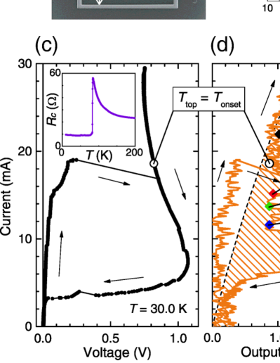
We studied two rectangular mesas, R1 and R2. R1 was prepared by milling a groove into the Bi-2212 substrate, but R2 was sandwiched between two Au layers. Further information on R1, R2, and three other mesas of various shapes are presented in the Supplemental Material SM . Figure 1(a) is a scanning ion microscope (SIM) picture of the top of R1, with –m, –m, and groove depth m, before the electrode attachments. R1 is 3% longer and wider at the bottom of the groove than at the top. Figure 1(b) is an atomic force microscope (AFM) scan of the groove profile along the A–B line in Fig. 1(a). From this value, we estimate the number of IJJs in the stack to be . The hysteresis loop indicated by the arrows in Fig. 1(c) is typical of the outermost branch of the - characteristics (IVCs) of an IJJ system. At the largest jump from to 0.85 V, all of the junctions switch into the resistive state simultaneously. In the high- bias region, R1 is inevitably Joule heated at a rate of mW. This huge power dissipation may cause the negative differential resistance between and 25 mA, since the -axis quasiparticle resistance has a strong -dependence as shown in the inset of Fig. 1(c). On the return region of the - loop where mA, we observed several small steps, indicating that some of the IJJs make the transition from the resistive to the superconducting state.
Figure 1(d) shows the R1 radiation output intensity generated from on the same scale as in Fig. 1(c). The dashed curve indicates the expected drift due to thermal radiation from the sample and its holder. Soon after the largest jump in the - loop, intense emission of EM waves was clearly observed. Strong spatial variation of the temperature over the top mesa surface was previously observed Wang09 ; Wang10 ; Guenon10 , and was thought to strongly affect the cavity mode-locking condition. We take to be the spatial average of the temperature on the mesa top. For R1, K with a width K. Below K, indicated by the open circles in Figs. 1(c) and 1(d), R1 makes the transition to the superconducting state, as shown in Fig. 1(d).
Figure 1(e) shows the radiation spectra, offset by 150 counts for clarity, measured at points A–E in Fig. 1(d), at which all of the IJJs are in the resistive state. The narrow and intense peaks in the emission spectra of B–E have maxima varying from 0.47 THz to 0.53 THz. The detector resolution-limited widths of the B, C peaks are too narrow to arise from synchronization by an internal cavity mode alone, and might involve heating effects Wang10 . Such outermost branch tunability of up to 40% was found previously by varying both and the bath Wang10 ; Kashiwagi11 ; Benseman11 . Although the wide range strongly violates the internal cavity resonance condition, , the ac Josephson relation for a stack of resistive IJJs Wang10 , , is excellently obeyed.
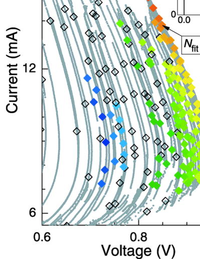
We found that EM emission also occurs at many points in the inner region of the multiply-branched IVCs, where is fixed but different for each branch. The synchronization of the IJJs on a single - branch is also not controlled by an internal cavity resonance Balanov09 , unlike some predictions Koshelev10 . In Figs. 2(a) and 2(b), the radiation frequencies, , are plotted as color-scaled symbols on the high-bias regions of the multiply-branched - structures for R1 at 35.0 K and R2 at 52.5 K, respectively. The insets show the full IVCs. All of the R1 curves in Fig. 2(a) bend backwards with increasing current, indicative of Joule heating Wang09 ; Wang10 ; Guenon10 ; Kurter10 . However, R2 is less susceptible to heating effects, and its IVCs in Fig. 2(b) are monotonic. The spectra were obtained at as many bias points as possible. At the bias points denoted by open diamonds, no emission was detected.
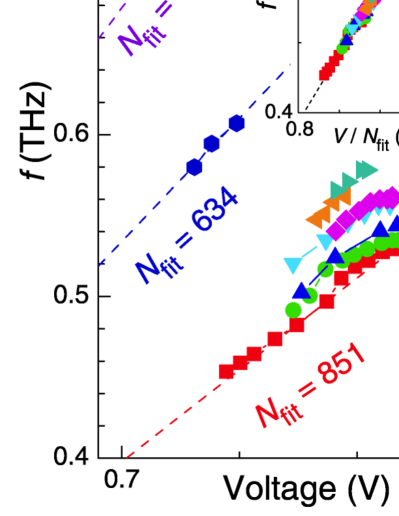
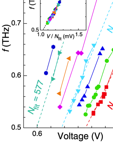
By repeated measurements of the emission from a particular - branch with constant , we confirmed that satisfies the ac Josephson relation . In Figs. 3(a) and 4(a), we replotted the emission data from the IVCs of R1 and R2 shown in Figs. 2(a) and 2(b) in terms of , representing the data from each branch in terms of unique symbols and colors. By fits of the data for a particular branch to the ac Josephson relation with , the experimental best-fit value for each emitting branch was determined. Three examples each for R1 and R2 are respectively indicated by the dashed lines in Figs. 3(a) and 4(a) and the arrows in Figs. 2(a) and 2(b). In the insets to Figs. 3(a) and 4(a), the entire emission data from the inner IVC branches of R1 and R2 are respectively plotted as . For both R1 and R2, the ac Josephson relation , represented by each dotted line, is well obeyed.
Since Figs. 3(a) and 4(a) clearly demonstrate that is slightly tunable on each branch (indicated by a fixed symbol and color), in Figs. 3(b) and 3(c), we respectively replotted the data from each R1 and R2 branch as . Although for both samples is tunable as indicated by the vertical bars for each fixed branch number , R1 and R2 display rather different aspects of tunability. The overall tunability of R1 and R2, which are respectively tunable from 0.44 THz 0.78 THz and from 0.43 THz0.76 THz, is nearly the same. However, for R1, this range is primarily due to the -dependence on - branch number, whereas for R2, the tunability is greatest on a single branch.
We measured the spectrum for each emitting point in the inner IVC branches of R1 and R2, and determined its peak intensity as for points B–E on the outer branch of R1 shown in Fig. 1(e). In Figs. 3(d) and 4(b), we plotted the peak intensity of the emissions on a logarithmic scale versus for R1 and R2, respectively, and is approximately coded with color. The ranges due to mesa profile variations of the respective internal cavity mode frequencies are indicated at the figure tops. For R1, no emission was found for THz, excluding the expected cavity resonance frequencies of 0.255 and 0.357 THz corresponding to the TMz(1,0) and TMz(0,1) modes. Moreover, the spectrum observed in Fig. 3(d) is almost completely unrelated to any of the internal cavity modes. For example, the strongest intensity observed for THz, corresponding to V, mA, and , is far from the two nearest cavity resonance frequencies. Although the indicated cavity frequency ranges could be shifted to higher frequencies by shorter effective or values due to hot spots Wang10 , since = 35 K in each measurement, such shifts could still not explain the broad range of observed frequencies. For , there are ways to have of the junctions in the resistive state, each of which could in principle lead to a different emission intensity. Hence, multiply cycling through the IVCs led to a large variation in peak intensity at that point. The synchronization of the resistive junctions thus occurs independently of the internal cavity mode excitations Balanov09 . More important, the emission spectrum in Fig. 3(d) is continuous from 0.44 THz 0.78 THz, except for a gap between 0.66 THz and 0.73 THz. The gap may be due to some experimental difficulty in accessing the appropriate branches. This widely continuous spectrum independent of internal cavity resonances implies that is broadly tunable. Figure 3(b) suggests that the values from lower branch-number emissions could exceed 1 THz. Further tunability might arise from base variations Wang10 , as discussed in the Supplemental Material SM .
The peak intensity spectrum of R2 measured at 52.5 K shown in Fig. 4(b) is also broadly tunable, with emission for 0.43 THz 0.76 THz, and a small gap between 0.67 and 0.75 THz. For R2, the range from 0.43 THz to 0.55 THz is below the range of the lowest cavity resonance frequency values. Unlike the peak intensity spectrum of R1, the largest intensity at 0.565 THz is close to this range. In this case, the synchronization of the resistive junctions could be aided by the excitation of this internal cavity mode Balanov09 ; Koshelev10 .
We measured the full angular dependence of the radiation from R2 on the outermost branch at THz, and the results are shown and discussed in the Supplemental Material SM . Although the observed angular dependence is similar to that expected from the low- tail of the TMz(1,0) cavity mode excitation, the frequency is far from , but could be amplified by excitation of a higher frequency mode, as indicated. We thus determined Kadowaki10 ; Tsujimoto10 ; Klemm10 ; Klemm11 that the angularly integrated output power at this frequency is W, somewhat smaller than previously reported Ozyuzer07 ; Kadowaki08 ; Minami09 ; Wang09 ; Ozyuzer09 ; Wang10 ; Guenon10 ; Kadowaki10 ; Tsujimoto10 ; Yamaki11 ; Kashiwagi11 ; Benseman11 . In addition, a much larger emission peak intensity, with an estimated overall emission power of 4.8 W, was found at 0.557 THz, which is much closer to . Besides the excitation of the TMz(1,0) mode, this strong inner branch emission could have been enhanced by R2 being sandwiched between two Au layers Klemm10 . More important, the large range in observed values well below the range is clear evidence that the highly tunable emission itself can occur without excitation of an internal cavity mode.
Although R1 was prepared by forming a groove into the Bi-2212 substrate, R2 stood atop a Au substrate. The heating effects and EM boundary conditions for R1 might be significantly different from those for R2 Koshelev10 . Although the synchronization of the junction emissions from R2 is likely to be enhanced by internal cavity resonances Bulaevskii07 , synchronization of the emissions from R1 could arise from the radiation itself Balanov09 , but is more likely to be enhanced by the shunt capacitance in the electrical circuit arising from the non-emitting insulating junctions in the adjacent Bi-2212 substrate Martin10 .
To determine whether the excitation of an internal cavity mode was an essential feature of the coherent radiation obtained from mesas of Bi-2212 under the application of across the stack of IJJs in the mesa, we examined the inner branches of the IVCs. We found these internal branches to emit radiation over a broad frequency range. Hence, we conclude that the primary source of the intense, coherent sub-THz radiation is the ac Josephson current, and that the internal EM cavity produced by the geometrical shape of the emitting mesa is at best of minor importance, and for one sample, completely irrelevant. Hence, broadband, tunable, continuous coherent radiation can be obtained in the sub-THz range from Bi-2212 mesas. Since the wavelength in vacuum is times longer than in the mesa, we propose that a high-power device can be constructed by surrounding the mesa with an external, tunable high- EM cavity Black01 ; Clark04 . By examining yet lower inner branches, it ought to be possible to increase the upper limit into the 1–10 THz range. Hence, it is now relatively straightforward to produce broadly tunable, continuous, coherent radiation over the range of the terahertz gap.
The authors thank X. Hu, S. Lin, A. Koshelev, M. Matsumoto, T. Koyama, M. Machida, H. Asai, S. Fukuya, and K. Ivanovic for valuable discussions and Y. Ootuka, T. Hattori, A. Kanda, I. Kakeya, B. Markovic, K. Yamaki, and H. Yamaguchi for technical assistance. This work was supported in part by CREST-JST (Japan Science and Technology Agency), WPI (World Premier International Research Center Initiative)-MANA (Materials Nanoarchitectonics) project (NIMS) and Strategic Initiative category (A) at the University of Tsukuba.
References
- (1) A. Borak, Science 308, 638 (2005).
- (2) M. Tonouchi, Nature Photon. 1, 97 (2007).
- (3) B. D. Josephson, Phys. Lett. 1, 251 (1962).
- (4) D. N. Langenberg et al., Phys. Rev. Lett. 15, 294 (1965).
- (5) I. K. Yanson, V. M. Svistunov, and I. M. Dmitrenko, JETP 21, 650 (1965).
- (6) P. Barbara et al., Phys. Rev. Lett. 82, 1963 (1999).
- (7) R. Kleiner et al., Phys. Rev. Lett. 68, 2394 (1992).
- (8) L. Ozyuzer et al., Science 318, 1291 (2007).
- (9) K. Kadowaki et al., Physica C 468, 634 (2008).
- (10) H. Minami et al., Appl. Phys. Lett. 95, 232511 (2009).
- (11) H. B. Wang et al., Phys. Rev. Lett. 102, 017006 (2009).
- (12) L. Ozyuzer et al., Supercond. Sci. Technol. 22, 114009 (2009).
- (13) H. B. Wang et al., Phys. Rev. Lett. 105, 057002 (2010).
- (14) S. Gunon et al., Phys. Rev. B 82, 214506 (2010).
- (15) K. Kadowaki et al., J. Phys. Soc. Jpn. 79, 023703 (2010).
- (16) M. Tsujimoto et al., Phys. Rev. Lett. 105, 037005 (2010).
- (17) K. Yamaki et al., Optics Exp. 19, 3193 (2011).
- (18) T. Kashiwagi et al., J. Phys. Soc. Jpn. 80, 094709 (2011).
- (19) T. M. Benseman et al., Phys. Rev. B 84, 064523 (2011).
- (20) L. N. Bulaevskii and A. E. Koshelev, Phys. Rev. Lett. 99, 057002 (2007).
- (21) S. Lin and X. Hu, Phys. Rev. Lett. 100, 247006 (2008).
- (22) M. Tachiki, S. Fukuya, and T. Koyama, Phys. Rev. Lett. 102, 127002 (2009).
- (23) R. A. Klemm and K. Kadowaki, J. Phys.: Condens. Matter 22, 375701 (2010).
- (24) R. A. Klemm et al., J. Phys.: Condens. Matter 23, 025701 (2011).
- (25) See Supplemental Material at [URL will be inserted by publisher] for experimental details.
- (26) A. Balanov et al., Synchronization: from Simple to Complex (Springer, Berlin, 2009).
- (27) A. E. Koshelev, Phys. Rev. B 82, 174512 (2010).
- (28) C. Kurter et al., Phys. Rev. B 82, 224518 (2010).
- (29) I. Martin et al., J. Appl. Phys. 108, 033908 (2010).
- (30) E. D. Black, Am. J. Phys. 69, 79 (2001).
- (31) A. H. Clark et al., IEEE J. Quant. Elect. 40, 878 (2004).