Bistability and all-optical memory in dual-mode diode lasers with time-delayed optical feedback
Abstract
A proposal for an all-optical memory based on a bistability of single-mode states in a dual-mode diode laser with time-delayed optical feedback is presented. The system is modeled using a multimode extension of the Lang-Kobayashi equations with injected optical pulses. We uncover the bifurcation structure by deriving analytical expressions for the boundaries of the bistable region and demonstrate how the delay time in the external cavity determines an optimal pulse duration for efficient switching of the memory element. We also show the relevant role played by gain saturation and by the dual-mode solutions of the Lang-Kobayashi equations for the existence of the bistable regions. Our results demonstrate that feedback induced bistability can lead to significant performance improvements when compared to memory elements based on the injection locking bistability in dual-mode devices.
I Introduction
Applications of all-optical signal processing as an alternative to electronic switching in telecommunication and computing networks drives continued interest in implementations of all-optical memory and optical logic Ramos2005 . Many approaches to these problems rely on the co-existence of lasing modes of a given system with injected optical pulses for switching between these states. Proposed memories have been based on counter-propagating modes in micro-ring devices Dorren2003 ; Hill2004 , polarization modes in VCSELs Mori2006 ; Mori2008 , wavelength bistable states induced by gain cross-saturation Ishii2005 ; Raburn2006 ; Zhukovsky2009 and bistable states induced by spatial hole burning effect in DFB lasers Huybrechts2008 .
Although switching performance in conventional edge-emitting diode lasers is constrained by speed limitations and power consumption, these devices represent testbeds for the study of the underlying dynamics based on generic systems of equations. Dynamical behaviours found in conventional diode laser systems may be scalable to integrated devices based on photonic crystals or microcavities, thus overcoming limitations of speed and power consumption. A recent example of this correspondence is provided by a comparison of the structure of the injection locking bistability in a dual-mode diode laser and a compact photonic crystal microlaser system that supports two lasing modes Osborne2009 ; Chen2011 . In both of these systems it was found that optical injection induced a bistability between the single mode injection-locked state and a dual-mode equilibrium state of the system. Switching of the optical memory was then based on modulated optical injection. Certain weaknesses of this proposal however included asymmetric states of the memory and the requirement for the optical injection itself, which played the role of an external holding beam. In this paper we propose an alternative but related system, which addresses many of the weaknesses of our earlier proposal. We consider wavelength bistability induced in a dual-mode diode laser by time-delayed optical feedback. We model this system using an extension of the equations describing the optically injected dual-mode system. This proposed memory element has many improved features when compared to devices based on injection-locking. These include improved speed, the absence of a holding beam and symmetry of the memory states.
This paper is organized as follows. In section II we study the single-mode and dual-mode equilibria of the dual-mode system relating these results to the well-known theory of single-mode lasers. In section III we show how bistability between single-mode equilibria appears in the dual-mode system for different external cavity lengths. We uncover the bifurcation structure underlying this bistability and derive analytical expressions for the boundaries of the bistable region. In section IV we analyze the bistable regions varying different parameters of the system and we study the role of the gain saturation in the dual-mode system. In section V we analyze the switching dynamics of the memory element and show how an optimal injected optical pulse duration is determined by the delay time of the system. Our results indicate that by scaling the dual-mode device to microlaser dimensions, switching speeds in the GHz range can be achieved with femtojoule injected pulses.
II Dual-mode L-K equations and external cavity modes
Our theoretical study is based on a multimode extension of the Lang-Kobayashi equations Lang1980 ; Sukow1999 ; Buldu2002 :
In the above equations, are the normalized complex electric fields associated with the two modes of the laser and is the normalized excess carrier density in the cavity. are the normalized complex fields delayed by the external cavity round trip time . The feedback strength is and is defined such that and , where and are the free running lasing mode frequencies and . and are the reference feedback phase and the feedback phase difference of the modes. The system is switched using optically injected pulses whose normalized complex fields are given by . Here the detunings are measured from the free running lasing mode frequencies. The quantity is the modal nonlinear gain function, where is the linear modal gain, is the gain self saturation and is the gain cross saturation. The phase-amplitude coupling is given by , is the normalized pump current, while is the product of the cavity decay rate with the carrier lifetime .
Equations (II) have validity within certain ranges of the external cavity length and of the feedback strength for two reasons. The first reason is that these equations take into account the propagation of the modal fields only in the external cavity and not in the laser cavity. Hence, we assume here that the external cavity length needs to be at least one order of magnitude greater than the laser cavity length. The second reason is that equations (II) take into account only a single reflection on the external mirror. Hence we assume that the feedback strength needs to be less than , as above this value multiple reflections in the external cavity should be taken into account.
For the parameters of the free running device we have used the following values: , , (35 above threshold), , , , , and . These values allow for a stable dual-mode equilibrium state in the free running device. The same parameters were successfully used to model an optically injected dual-mode system where the primary modes had a frequency spacing of 480 GHz and the device length was 350 m Osborne2009 ; Osborne2009_PRA ; OBrien2010 .
Equations (II) allow for two different kinds of solutions: single-mode solutions and dual-mode solutions. The single-mode solutions of equations (II) are the external cavity modes (ECMs) of the system Mork1992 ; Heil2003 . These ECMs are obtained assuming the ansatz in equations (II) and zero intensity individually for each modal field. These solutions can be regarded as “equilibrium states” when considering that their amplitudes and frequencies are constant in time. In this paper, we refer to these oscillatory solutions as “equilibrium states” in this sense. The single-mode ECMs of the dual-mode system are described by the following equations:
Here is defined as the detuning of each ECM with respect to the frequency of the associated free running laser mode, is the ECM intensity, and is the ECM total feedback phase. Each ECM of the system is associated with a unique value of the detuning, which can vary from a few gigahertz to tens of gigahertz.
The linear stability analysis of the single-mode ECMs of equations (II) within the single-mode sub-manifolds of the dual-mode system demonstrates that the single mode ECMs are born in pairs with a stable ECM and an unstable ECM generated through saddle-node bifurcations. This analysis leads to the following condition for the stability of the single-mode ECMs Acket1984 ; Tromborg1984 :
| (3) |
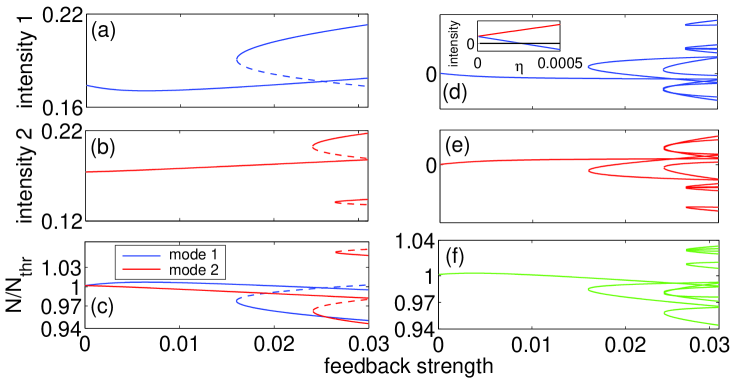
When the above condition is satisfied the single-mode ECMs are stable within the single-mode sub-manifolds of the dual-mode system with respect to the saddle-node bifurcation, while these ECMs are unstable when this condition is greater than zero. Using equations (II) we can study the evolution of the single-mode ECMs while varying the feedback strength, as shown in Figure 1 (a), 1 (b) and 1 (c). Here we have considered an external cavity length of 1 cm and a laser cavity length of the order of few hundred micrometres. Because of the large primary mode spacing, and can be considered free parameters that can be tuned through a relatively small displacement of the external mirror. We have chosen the values and for obtaining the maximum switching speed of the considered device.
In Figure 1 (a) and 1 (b) we plot the single-mode ECM intensity, while in Figure 1 (c) we plot the single-mode ECM normalized carrier-density. In these figures solid and dashed lines denote respectively stable and unstable ECMs in the single-mode sub-manifolds of the dual-mode system. The stability of these ECMs is obtained using equation (3). One can also see the presence of saddle-node bifurcations where stable and unstable branches collide.
A fundamental feature of the dual-mode system we consider is the existence of dual-mode solutions, which are derived from equations (II), assuming the ansatz and non-zero intensity for both modal fields. These solutions are given by the following equations:
| (4) | |||||
Here , plus and minus signs refer respectively to mode 1 and mode 2. dual-mode equilibrium solutions involve two independent detunings which are equal to the values determined by the single-mode ECMs. They can therefore be regarded as ECM pairs obtained from nonlinear combinations of the single-mode solutions. Because the dual-mode solutions are defined with a single common carrier density, they in general involve a redistribution of the intensity from the single-mode values. We have used equations (4) for plotting the intensities and the carrier density of the dual-mode solutions in Figure 1 (d), 1 (e) and 1 (f) as a function of feedback strength with the same parameters as in Figure 1 (a) - (c). In Figure 1 there are regions where the dual-mode solutions are unphysical with negative value of one of the modal intensities. One can also see that for each saddle-node of the single-mode ECMs a corresponding saddle-node of dual-mode solutions occurs. Furthermore for vanishing feedback strength only a single dual-mode solution exists, which corresponds to the stable free running dual-mode equilibrium perturbed by the feedback. This can be seen in the inset of Figure 1, where the intensities of the two modes converge towards the free running dual-mode equilibrium.
III Bistability induced by time-delay
In the dual-mode system described by equations (II) bistability between single-mode ECMs can be observed. This is shown in the bifurcation diagrams of the modal intensities in Figure 2 (a) and 2 (b). Here the feedback parameters are the same as in Figure 1. In these figures one can see that, as the feedback strength is increased from zero, the system evolves into a stable single-mode ECM of mode 2, followed by a Hopf bifurcation and a region of coupled complex dynamics. For a further increase of the feedback strength a single-mode ECM of mode 2 is the only stable state until a pair of single-mode ECMs of mode 1 are generated through a saddle-node bifurcation, labelled SN1. At this saddle-node bifurcation a region of bistability appears where the unique single-mode ECM of mode 2 and the single-mode ECM of mode 1 associated with the stable branch of the saddle-node bifurcation SN1 co-exist. This bistable region is bounded when the single-mode ECM of mode 2 loses stability at a point which we label . Following this, the single-mode ECM of mode 1 is the only stable state of the system. For a further increase of the feedback strength we found a stable dual-mode equilibrium followed by a stable single-mode ECM of mode 2.
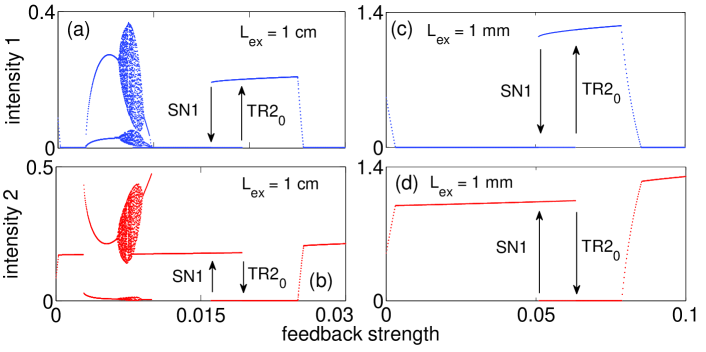
A bistable region between single-mode ECMs can also be found for a system with 1 mm external cavity length, as one can see in Figure 2 (c) and 2 (d). This is a limiting case appropriate to a dual-mode microlaser with a cavity length of order one hundred micrometres Zhukovsky2009 ; Chen2011 . In this case, we have increased by a factor of three to reflect the possibility of increased optical losses in the microlaser system. This leads to an increase of the current threshold density by a factor of three. We also choose a pump current five times greater than the current threshold, which leads to an increase of the relaxation oscillation frequency and of the damping factor of the free running device. The increased relaxation oscillation frequency and damping can lead to faster switching transients for the memory.
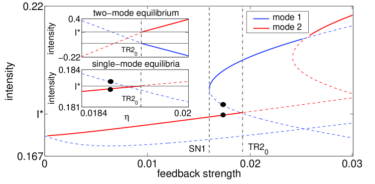
In order to understand the bifurcation at the upper boundary of the bistable region, in Figure 3 we have plotted the intensity of the single-mode ECMs of interest for a device with 1 cm external cavity length. One can see the branches of single mode ECMs of mode 1, which appear at the saddle-node bifurcation SN1. In the upper inset of Figure 3 we plot the modal intensities of a dual-mode solution of the system in a range close to the bifurcation . As indicated by the filled circles in Figure 3, this dual-mode solution is derived from the single-mode ECM of mode 1 associated with the unstable branch of the bifurcation SN1 and from the single-mode ECM of mode 2 associated with the free running solution. The modal intensities of these single-mode ECMs have been plotted in the lower inset of Figure 3. From the two insets we can see that the upper boundary of the bistable region is found where one of the fields associated with the dual-mode solution becomes equal to zero. The upper boundary of the bistable region is then understood as resulting from a collision between a stable single-mode ECM of mode 2 with an unstable dual-mode solution. These solutions exchange their stability in a transcritical bifurcation with the dual-mode solution becoming unphysical with a negative value for the intensity of mode 1 after the bifurcation.
Stability of single-mode ECMs in the larger dual-mode system requires that they be stable with respect to perturbations in the direction transverse to the single-mode sub-manifolds of the system. Here, stability requires that eigenvalues of the zero field part of the single-mode solutions are transversally stable with respect to the carrier density value given by equation (II). As the amplitude of the perturbed field is zero, the problem is linear and leads to the following condition for transverse stability of single-mode ECMs:
| (5) |
Here denotes the real part of the complex eigenvalue , is the Lambert function defined as the solution of the equation Andreas2007 . is defined such that and . is defined such that and . Equation (5) determines an additional stability criterion, which together with equation (3) determines necessary conditions for stability of the single-mode ECMs of the system. Continuous and dashed lines in Figure 3 respectively denote stable and unstable single-mode ECMs obtained in this way.
IV Bistable regions and role of the gain saturation
A complete understanding of the stability of the single-mode ECMs in the dual-mode system considered here can be obtained through equations (3) and (5). We have used these equations to plot the boundaries of the bistable region varying the feedback strength and the feedback phase difference. The results are shown in Figure 4 (a) for a system with 1 cm external cavity length and . In figure 4 (a) only the bifurcation lines related to the boundaries of the bistable regions have been plotted. The bistable regions have been labeled using the notation which indicates bistability between single-mode ECMs of mode m and ECMs of mode j. The label SNm indicates a saddle-node bifurcation of mode m. The label denotes a transcritical bifurcation of mode m between a single-mode ECM associated with the free running solution and a dual-mode equilibrium. The label denotes a transcritical bifurcation for mode m between a single-mode ECM born in the first saddle-node bifurcation of mode m and a dual-mode equilibrium. The integer numbers 1, 3, 5 indicate the number of single-mode ECMs of the system following each saddle-node bifurcation.
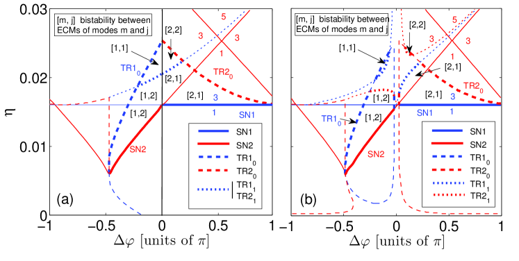
In Figure 4 (a) we observe four bistable regions. For lower values of there are two large bistable regions, labelled and , which are characterized by a structure of the single-mode ECMs similar to the plots of Figure 3. In this case, the label indicates that the ECMs generated by the saddle-node bifurcation are associated with mode 2, while the label indicates that these ECMs are associated with mode 1. For higher values of we found the bistable regions labelled and , where we found bistability between ECMs of the same mode. These regions can be the basis of an optical memory where the wavelength channels are almost degenerate in frequency.
A non-zero gain saturation parameter can influence the position of the bifurcations at the boundaries of the bistable regions. This can be understood by comparing Figure 4 (a) with Figure 4 (b), where the bifurcations at the boundaries of the regions have been plotted for the device with 1 cm external cavity length and . The main effect of the introduction of a non-zero gain saturation parameter is that the four bistable regions become non-adjacent. This separation of the bistable regions is due to the absence of the degeneracy between the bifurcations and and between and . In order to understand the physical mechanism that governs the degeneracy of these bifurcations we study the dual-mode equilibrium of equations (II) for , which can be written as follows:
| (6) | |||||
Equations (6) define a unique value of the excess carrier density and a unique value of the sum of the modal intensities, but do not uniquely define the two individual modal intensities. This means that these equations are solved by a continuous set of values of the modal intensities. Therefore equations (6) define an invariant set of points in the phase space of the dual-mode system. We note also that the two conditions that define the dual-mode carrier density in equations (6) coincide with the expressions for the single-mode carrier densities in equations (II) for . Physically, this means that for the dual-mode equilibrium states exist only when the excess carrier densities associated with the single-mode equilibria are degenerate. Thus the invariant set of dual-mode equilibrium states exist at isolated points where they enable the transcritical bifurcations at the boundaries of the bistable regions.
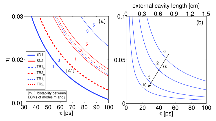
Equations (3) and (5) also enable us to study the width of the bistable region as the delay time is decreased. In this case we have found that although the bistable region remains open for vanishing delay time, the feedback strength required to observe the bistability diverges in this limit. This is shown in Figure 5 (a) where we plot the transcritical and saddle-node bifurcations of the single-mode ECMs for varying external cavity length and other parameters as in Fig. 3. In this figure there is only one bistable region with a structure similar to the bistability presented in Figure 3. The saddle-node line of mode 1 that opens the bistable region plotted in Figure 5 (a) defines the minimum feedback strength and the minimum delay time required for observing this bistablility. It is interesting to note also that these minimum values can be reduced increasing the parameter. This is shown in Figure 5 (b) where the lower boundary of the bistable region has been plotted for different values of .
V Switching dynamics of the optical memory
The dual-mode system described by the equations (II) in the bistable regime can be used as optical memory when optical pulses are injected in this system at frequencies corresponding to the detunings of the external cavity modes. In Figure 6 (a) and 6 (b) we have studied the switching dynamics of a system with external cavity length of 1 cm. We have used the parameters GHz, GHz, , . Optical pulses with a duration of 100 ps have been injected at the instants indicated by the arrows. The memory is switched with a frequency of 500 MHz with a pump current at 35 above threshold. The two modes show transients with the presence of several fast spikes. In Figure 6 (c) and 6 (d) the switching dynamics of the modal intensities have been plotted with an external cavity length of 1 mm. The parameters used are GHz, GHz, , and . The memory is switched with a frequency of 5 GHz using optical pulses with a duration of 10 ps. This increase of one order of magnitude of the switching speed is consistent with the increase of the relaxation oscillation frequency due to the increase of the pump current and of the cavity decay rate.
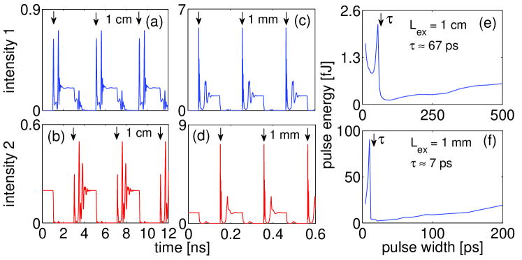
In Figure 6 we plot the minimum pulse energy as a function of the pulse duration for systems with external cavity lengths of 1 cm and 1 mm. We have defined this minimum pulse energy by requiring that the switching transients be strongly damped before the arrival of the next switching pulse. For pulse durations larger than the delay time, we observe that the energy required for switching the system decreases linearly as the pulse duration is decreased. The minimum pulse energy in each case corresponds to a pulse duration close to but greater than the delay time. This result can be understood when we consider that the switching pulse is injected in a mode of the system which has zero field amplitude. If the pulse duration is longer than the external cavity round trip time then the leading edge of the pulse interacts with the system and the output is fed back before the arrival of the trailing edge. The zero field mode is then continuously fed with energy during the switching process. In Figure 6 (e) and 6 (f) the optimal pulse energy we obtain is of a few femtojoules in each case. These results suggest that feedback induced bistability in microlaser systems can lead to compact all-optical memories with switching speeds in the GHz range and injected pulse energies of a few femtojoules.
VI Conclusions
In conclusion, we have presented an analytical and numerical study of the bifurcation structures of the bistability between single-mode equilibria in dual-mode diode laser systems with time delayed optical feedback. We have proposed an all-optical memory based on this bistability, which shows attractive features in the context of in-plane all-optical signal processing, including the short external cavity length, the self-sustained nature of the feedback system, and the symmetry of the memory states. The optimal pulse duration has been shown to be determined by the delay time of the system. With feedback parameters appropriate to dual-mode devices based on conventional edge-emitting diode lasers, switching frequencies of at least 500 MHz with 100 ps pulses should be possible. This would represent a significant improvement on the performance of a memory element based on the injection locking bistability in a conventional device. We also considered the limit of a very short external cavity length equal to 1 mm, which may be appropriate for certain photonic crystal microlaser structures. In this case we obtained memory switching frequencies up to 5 GHz using 10 ps injected optical pulses and with pulse energies of a few femtojoules.
Acknowledgements
The authors wish to thank Science Foundation Ireland for financial support of this work.
References
- (1) F. Ramos, E. Kehayas, J. M. Martinez, R. Clavero, J. Marti, L. Stampoulidis, D. Tsiokos, H. Avramopoulos, J. Zhang, P. V. Holm-Nielsen, N. Chi, P. Jeppesen, N. Yan, I. T. Monroy, A. M. J. Koonen, M. T. Hill, Y. Liu, H. J. S. Dorren, R. V. Caenegem, D. Colle, M. Pickavet, and B. Riposati, “IST-LASAGNE: towards all-optical label swapping employing optical logic gates and optical flip-flops,” Journal of Lightwave Technology, vol. 23, pp 2993-3011, 2005.
- (2) H. J. S. Dorren, M. T. Hill, Y. Liu, N. Calabretta, A. Srivatsa, F. M. Huijskens, H. de Waardt, and G. D. Khoe, “Optical packet switching and buffering by using all-optical signal processing methods,” Journal of Lightwave Technology, vol. 21, pp 2-12, 2003.
- (3) M. T. Hill, H. J. S. Dorren, T. de Vries, X. J. M. Leijtens, J. H. den Besten, B. Smalbrugge, Y. Oei, H. Binsma, G. Khoe, and M. K. Smit, “A fast low-power optical memory based on coupled micro-ring lasers,” Nature, vol. 432, pp 206-209, 2004.
- (4) T. Mori, Y. Yamayoshi, and H. Kawaguchi, “Low-switching-energy and high-repetition-frequency all-optical flip-flop operations of a polarization bistable vertical-cavity surface-emitting laser,” Appl. Phys. Lett., vol. 63, 101102, 2006.
- (5) T. Mori, Y. Sato, and H. Kawaguchi, “10 Gb/s optical buffer memory using a polarization bistable VCSEL,” IEICE Trans. Electron., E92C, pp 957-963, 2009.
- (6) S. Ishii, and T. Baba, “Bistable lasing in twin microdisk photonic molecules,” Appl. Phys. Lett., vol. 87, 181102, 2005.
- (7) M. Raburn, M. Takenaka, K. Takeda, X. Song, J. S. Barton, and Y. Nakano, “Integrable multimode interference distributed Bragg reflector laser all-optical flip-flops,” IEEE Photon. Technol. Lett., vol. 18, pp 1421-1423, 2006.
- (8) S. V. Zhukovsky, and D. N. Chigrin, “Optical memory based on ultrafast wavelength switching in a bistable microlaser,” Optics Letters, vol. 34, pp 3310-3312, 2009.
- (9) K. Huybrechts, G. Morthier, and R. Baets, “Fast all-optical flip-flop based on a single distributed feedback laser diode,” Optics Express, vol. 16, pp 11405-11410, 2008.
- (10) S. Osborne, K. Buckley, A. Amann, and S. O’Brien, “All-optical memory based on the injection locking bistability of a two-color laser diode,” Optics Express, vol. 17, pp 6293-6300, 2009.
- (11) C. H. Chen, S. Matsuo, K. Nozaki, A. Shinya, T. Sato, Y. Kawaguchi, H. Sumikura, and M. Notomi, “All-optical memory based on injection-locking bistability in photonic crystal lasers,” Optics Express, vol. 19, pp 3387-3395, 2011.
- (12) R. Lang, and K. Kobayashi, “External optical feedback effects on semiconductor injection laser properties,” IEEE J. Quantum Electron., vol. 16, pp 347-355, 1980.
- (13) D. W. Sukow, T. Heil, I. Fischer, A. Gavrielides, A. Hohl-AbiChedid, and W. Elsäßer “Picosecond intensity statistics of semiconductor lasers operating in the low-frequency fluctuation regime,” Phys. Rev. A, vol. 60, pp 667-673, 1999.
- (14) J. M. Buldú, F. Rogister, J. Trull, C. Serrat, M. C. Torrent, J. García-Ojalvo, and C. R. Mirasso, “Asymmetric and delayed activation of side modes in multimode semiconductor lasers with optical feedback,” Journal of Optics B: Quantum and Semiclassical Optics, vol. 4, pp 415-420, 2002.
- (15) S. Osborne, A. Amann, K. Buckley, G. Ryan, S. P. Hegarty, G. Huyet, and S. O’Brien, “Antiphase dynamics in a multimode semiconductor laser with optical injection,” Phys. Rev. A, vol. 79, 023834, 2009.
- (16) S. O’Brien, S. Osborne, D. Bitauld, and A. Amann, “Design and applications of discrete mode Fabry-Pérot diode lasers,” Photonics and Nanostructures - Fundamentals and Applications, vol. 8, pp 218-227, 2010.
- (17) J. Mork, B. Tromborg, and J. Mark, “Chaos in semiconductor lasers with optical feedback: theory and experiment,” IEEE J. Quantum Electron., vol. 28, pp 93-108, 1992.
- (18) T. Heil, I. Fischer, W. Elsäßer, B. Krauskopf, K. Green, and A. Gavrielides, “Delay dynamics of semiconductor lasers with short external cavities: bifurcation scenarios and mechanisms,” Phys. Rev. E, vol. 67, 066214, 2003.
- (19) G. A. Acket, D. Lenstra, A. J. den Boef, and B. H. Verbeek, “The influence of feedback intensity on longitudinal mode properties and optical noise in index-guided semiconductor lasers,” IEEE J. Quantum Electron., vol. 20, pp 1163-1169, 1984.
- (20) B. Tromborg, J. H. Osmundsen, and H. Olesen, “Stability analysis for a semiconductor laser in an external cavity” IEEE J. Quantum Electron., vol. 20, pp 1023-1032, 1984.
- (21) A. Amann, E. Schöll, and W. Just, “Some basic remarks on eigenmode expansions of time-delay dynamics,” Physica A, vol. 373, pp 191-202, 2007.