Shock Dissipation in Magnetically Dominated Impulsive Flows
Abstract
The idea that cosmic relativistic jets are magnetically driven Poynting-dominated flows has many attractive features but also some problems. One of them is the low efficiency of shock dissipation in highly magnetized plasma. Indeed, the observations of gamma ray bursts (GRBs) and their afterglow emission indicate very high radiative efficiency of relativistic jets associated with these phenomena. We have revisited the issue of shock dissipation and emission and its implications for the internal shock model of the prompt GRB emission and studied it in the context of impulsive Poynting-dominated flows. Our results show that unless the magnetization of GRB jets is extremely high, in the prompt emission zone, the magnetic model may still be compatible with the observations. First, for the dissipation efficiency of fast magnetosonic shock is still quite high, . Second, the main effect of reduced dissipation efficiency is merely an increase in the size of the dissipation zone and even for highly magnetised GRB jets this size may remain below the external shock radius, provided the central engine can emit magnetic shells on the time scale well below the typical observed variability scale of one second. Our analytical and numerical results suggest that magnetic shells begin strongly interact with each other well before they reach the coasting radius. As the result, the impulsive jet in the dissipation zone is best described not as a collection of shells but as a continuous highly magnetised flow with a high amplitude magnetosonic wave component. How exactly the dissipated wave energy is distributed between the radiation and the bulk kinetic energy of radial jets depends on the relative rates of radiative and adiabatic cooling. In the fast radiative cooling regime, the corresponding radiative efficiency can be as high as the wave contribution to their energy budget, independently of the magnetization. Moreover, after leaving the zone of prompt emission the jet may still remain Poynting-dominated, leading to weaker emission from the reverse shock compared to non-magnetic models. Energetically sub-dominant weakly magnetized “clouds” in otherwise strongly magnetised jets may significantly increase the overall efficiency of the shock dissipation.
keywords:
MHD — relativity — gamma-rays: bursts — ISM: jets and outflows — galaxies: jets1 Introduction
Various astronomical observation indicate, directly or indirectly, the existence of highly relativistic outflows in a variety of cosmic phenomena, such as active galaxies, pulsar wind nebulae, X-ray binary stars, and Gamma Ray Bursts (GRBs). Although the origin of these flows is still a subject of debate, especially in the case of GRBs, and requires further investigation, so far we have identified only one mechanism of jet production which may operate in all these very diverse environments – the magnetic mechanism. This is one of the reasons why this mechanism has attracted so much attention in recent years.
It has been shown that magnetic fields can not only tap the rotational energy of a massive rotator, placed in the “hart” of “cosmic jet engines” in this model, but also accelerate and collimate outflows. In fact, it has been shown that in the case of relativistic steady-state jets, their magnetic acceleration and collimation go hand-in-hand and for this reason this version of magnetic mechanism is called the collimation acceleration mechanism. In order to ensure efficient magnetic acceleration, the jet opening angle should be small compared to the jet Mach angle associated with fast magnetosonic waves (Komissarov et al., 2009a). In the small angle approximation, the Mach angle
where is the fast magnetosonic Mach number. In the case of predominantly asymuthal magnetic field this number can be estimated using Eq.4 and the acceleration condition reads
where . In order to understand where this limitation comes from, consider a freely expanding conical jet. If its magnetic field is predominantly azimuthal than the magnetic freezing yields and the magnetic energy is not utilised to accelerate the flow. The flow geometry has to deviate from the conical one in order for the magnetic acceleration to operate and this requires efficient causal communication across the flow (e.g. Komissarov, 2011). In fact, the above causality condition is a bit too strict and the acceleration may proceed, though at a much lower logarithmic rate, even after it is no longer satisfied. However, the above constraint on remains valid up to a factor of few (Lyubarsky, 2009). For AGN jets with their inferred and observed this yields , whereas for the commonly accepted parameters of GRB jets, and , the last equations implies .
The observed variability of the emission produced in these jets has been traditionally associated with strong shock waves, driven into the jets by their unsteady central engines (see the review by Piran, 2004). Their observed bright knots and spots have also been attributed to such internal shocks. Indeed, shocks are generally known as places of effective dissipation of kinetic energy and acceleration of relativistic electrons, responsible for the non-thermal emission observed in many astrophysical objects. However, in the case of relativistic magnetized flows this interpretation encounters significant problems, particularly in the case of GRB jets (e.g. Narayan et al., 2011).
Indeed, the dissipation efficiency of relativistic shocks in highly magnetized plasma is rather low. This was widely accepted already after the pioneering work by Kennel & Coroniti (1984). To be more accurate, this statement is concerned with fast magnetosonic shocks only. Slow magnetosonic shocks can still have very high dissipation efficiency, because at such shocks the magnetic energy can be dissipated as well (Lyubarsky, 2005). However, fast shocks are much more readily produced, usually via collisions, whereas formation of slow shock requires some rather special conditions.
In contrast, the observations indicate that the jet radiative efficiency, , defined as the fraction of jet energy eventually converted into radiation (usually non-thermal), can be quite high. For example, the observations of the GRB afterglows imply that the radiative efficiency of their jets is often in excess of and sometimes may even reach (Panaitescu & Kumar, 2002; Yost et al., 2003; Granot et al., 2006; Zhang et al., 2007a). According to the more recent study of Swift GRBs the situation is even more dramatic, with the mean radiative efficiency around (Willingale et al., 2007). This difficulty of the shock model has forced many theorists to start looking for alternative models involving direct dissipation of magnetic energy associated with the magnetic reconnection (e.g. Drenkhahn & Spruit, 2002; Zhang & Yan, 2011; McKinney & Uzdensky, 2010; Lyubarsky, 2010). However, these models still remain at a rather rudimentary level of development due to difficulties of their own.
In most of the previous theoretical studies of magnetized relativistic jets it was assumed that they were more or less homogeneous, just for sake of simplicity. The strong observed variability and the complex observed structure of some relativistic jets, where high resolution images are available, suggest that this may be not a very realistic assumption. Following the early work by Contopoulos (1995), a number of recent papers explored the implications of highly intermittent jet production on its dynamics (Granot et al., 2010; Lyutikov, 2010; Lyutikov & Lister, 2010; Lyutikov, 2011; Granot, 2011a, b). They have concluded that longitudinal expansion of highly magnetised plasma shells may result in efficient conversion of the Poynting flux into the bulk kinetic energy of the shells and strong reduction of their magnetisation. However, in those papers only the dynamics of a single shell was studied in details, whereas the case of an impulsive jet composed of many such shells was subjected to a much more speculative analysis. The main goal of our study was to reduce this imbalance.
As a first step in studying of the multiple shell case one may assume that the gaps between them are empty. However, if the jet engine does indeed operate in an impulsive fashion then external plasma, presumably of much lower magnetization, is likely to fill the gaps during quiescent periods. Then each time the jet is reborn it has to push this plasma aside. Provided the jet is sufficiently powerful, this can be done quite efficiently by the bow-shock developing at the jet head (e.g. Komissarov & Falle, 1998). Farther out, where the distance between shells becomes comparable to the jet radius, the relativistic effects make impossible for the external plasma to enter the gaps (Lyutikov & Lister, 2010). At the same time it becomes impossible for the entrained plasma to leave the gaps as it is forced to remain within the cone of the half-opening angle . Thus, it seems quite plausible that some of the external plasma will remain in the gaps and become part of the jet, though it is still rather difficult to quantify the effectiveness of this mass-loading process at present.
On one hand, loading Poynting-dominated jets with weakly magnetised clouds complicates the problem. On the other hand, this may play a very important role in their physics. As far as the radiative efficiency is concerned, these clouds could be the locations there most of the shock dissipation and emission takes place. Very much in the same way as in the model of the afterglow emission, where a magnetic piston drives the so-called external shock wave through weakly magnetised interstellar medium (e.g. Lyutikov & Blandford, 2003; Zhang & Kobayashi, 2005; Lyutikov, 2006). Obviously, these clouds may have to be “excited” many times before a significant fraction of magnetic energy is radiated.
A similar repetitive “pumping” action has been investigated by Kobayashi & Sari (2001) in the case of unmagnetized highly variable jets. As individual shells (portions of the jet moving with very different Lorentz factors) collide and heat-up, only a fraction of the dissipated energy is radiated. The rest of it remains initially in the form of heat, but later, when the shells begin to expand, this heat is converted back into the kinetic energy of relative motion. When another collision occurs, a fraction of this energy is dissipated and radiated again and so on. The process continues until the shocks become very weak. Kobayashi & Sari (2001) have demonstrated that this way the radiative efficiency can be increased up to , even if during each individual collision only of the dissipated energy is radiated. However in order to achieve this, they required very strong variations of the jet Lorentz factor, with uniform distribution of between 1 and 4. Since in our case the energy behind this dynamics is of magnetic nature, the name “magnetic pump” springs to mind. In fact, each time the shock-heated gap plasma expands and its components, which are unable to cool radiatively, cool adiabatically their thermal energy is returned back to the “pump” and recycled.
The whole problem of impulsive jet dynamics from its production to its interaction with the interstellar matter is still prohibitively complex. In order to make progress, we will consider much simpler problems hoping to elucidate some of its important aspects. We start with the issue of the dissipation efficiency of fast magnetosonic shocks in highly magnetized plasma as we feel need to clarify few important points. This is done in Section 2 and in Appendix A. Then we consider strictly periodic one-dimensional flows in slab geometry in the framework of one fluid MHD with simple polytropic equation of state. In Section 3 we study oscillations developing in a periodic train of initially stationary magnetic shells, as they expand, collide and radiatively cool. Then we consider moving trains with initially empty gaps, following Granot et al. (2010), first in the adiabatic regime (Section 4) and then in the regime of fast radiative cooling (Section 5). Finally, we study the dynamics of a moving train with gaps filled with weakly magnetised plasma from the start in the fast radiative cooling regime (Section 6). The results and their astrophysical implications are discussed in Section 7. Our conclusions are listed in Section 8.
Throughout most of the paper we use the Heaviside units, where and , but in the Discussion we reintroduce the speed of light.
2 Dissipation efficiency of perpendicular fast magnetosonic shocks.
Here we consider only the perpendicular relativistic shocks, where the flow velocity is perpendicular to the shock front. In addition we assume that the magnetic field is parallel to the shock front. Thus, we restrict our attention to purely one-dimensional flow directed perpendicular to the magnetic field. This constraint prohibits slows magnetosonic waves of any kind and the only non-trivial shocks solutions are the fast magnetosonic ones. Such shocks were first studied by Kennel & Coroniti (1984) in application to the termination shocks of pulsar winds. In order to simplify the shock equations, they only considered the case of cold upstream flow, ultrarelativistic shock speed, and high shock strength, in the sense that the downstream Lorentz factor is much lower compared to the upstream one. All these additional constrains are justified in the case of pulsar wind nebulae. The general case of magnetosonic shocks was analysed by Majorana & Anile (1987) and Apple & Camenzind (1988). Later, Zhang & Kobayashi (2005) expanded the analysis of Kennel & Coroniti (1984) by allowing variable shock strength, which they described by the Lorentz factor of the relative motion between the upstream and downstream states, . Although this parameter can indeed be used to describe the shock strength, the more traditional parameter, unanimously accepted in the non-relativistic hydrodynamics and MHD, is the shock Mach number. The proper relativistic definition of Mach number with respect to the wave mode of speed in the fluid frame is
| (1) |
where is the Lorentz factor corresponding to the wave speed and is the Lorentz factor corresponding to the flow speed (Königl, 1980).


In the limit of cold plasma, where the thermodynamic pressure, , and hence the sound speed are set to zero, the fast magnetosonic speed is the same in all directions
| (2) |
where and are the magnetic field strength and the gas rest mass density as measured in the fluid frame, and
| (3) |
is one of the parameters describing the plasma magnetization. For and the fast magnetosonic Mach number is
| (4) |
In Appendix A we redo the analysis of perpendicular fast shocks of Zhang & Kobayashi (2005) using the Mach number with respect to the fast magnetosonic mode as the shock strength parameter. While in general numerical techniques have to be used to solve the shock equations, in the limit of high shock Mach number, , and high upstream magnetisation, , they allow simple approximate solution where
| (5) |
| (6) |
| (7) |
| (8) |
where is the magnetic pressure. Here index “1” refers to the upstream and index “2” to the downstream state. One can see that for there are strong jumps in the rest mass density and magnetic pressure as measured in the fluid frame. This is what is meant by Zhang & Kobayashi (2005), when they state that high magnetisation does not prevent development of strong shocks. On the other hand, if we consider parameters measured in the shock frame, which will be indicated by prime, then
| (9) |
| (10) |
where is the rest mass, not the inertial mass, density. Eq.9 shows that there is no much decrease in the shock frame volume occupied by plasma as it crosses the shock – the large decrease in the proper specific volume is almost totally compensated by the reduced Lorentz contraction. It is this what is meant when shocks in highly magnetised medium are often described as weak or weakly compressive.
One can define the shock dissipation efficiency in many different ways, some more meaningful than others. We are interested in the fraction of the total energy flux which can be converted into radiation without invoking any additional dissipations mechanisms, like the magnetic reconnection, downstream of the shock. This suggests to define the efficiency as
| (11) |
where is the thermal energy flux density and is the total energy flux density, is the thermal energy density and is the relativistic enthalpy, both defined in the fluid frame. Notice that this definition makes independent on the flow velocity, and hence on the shock speed relative to the observer. For we find
| (12) |
(see Appendix A ).


Equation (12) shows that for only a rather small fraction of the flow energy can be dissipated and then radiated away. In order to see if the same conclusion applies to shocks in only moderately magnetized plasma we solved the shock equations numerically. The results are presented in Figures (1) and (2). The left panel of Fig.(1) shows the dissipation efficiency as a function of for three different values of the shock fast magnetosonic Mach number, and 100. One can see that for the dissipation efficiency does indeed decline as . However, for small magnetization the efficiency actually increases with . The location of the maximum depends on the shock Mach number and for weak shocks is near . However, its magnitude is rather low in this case. As one can see in the right panel of Fig.1 the efficiency monotonically increases with the shock Mach number.
The collimation acceleration of magnetic jets may result in the asymptotic magnetization . For this reason we presented in the right panel of Fig.1 the dissipation efficiency as a function of the shock Mach number for around this value. For very high Mach number the efficiency is 0.3, and 0.05 for 1, and 10 respectively. This shows that for the dissipation efficiency can be already reasonably high. Moreover, Eq.12 gives a rather accurate estimate of the efficiency for and .
The shock solution depends on the plasma equation of state (EOS) but not strongly, at least for the explored range of parameters. In the right panel of Fig.1 the solid lines show the solution for the polytropic equation of state with (), whereas the dashed lines show the solution for the electron-positron Synge gas, which assumes the same temperature relativistic Maxwell distribution for every species (Synge, 1957). One can see that difference is relatively small, particularly for strong shocks. We also experimented with the electron-proton Synge gas and found that the solution was even closer to that with the polytropic EOS.
The result (12) has a straightforward interpretation. First, only the kinetic energy dissipates at the shock. Second, the kinetic energy flux makes only of the total upstream energy flux. Finally, for high approximately one half of the kinetic energy dissipates into heat, and approximately one half is converted into Poynting flux. This is illustrated in Fig.2 which shows fractions of the upstream kinetic energy converted at the shock into the thermal energy, , magnetic energy, , and remaining in the kinetic form, .
3 Chamber oscillations
Collisions between shells will produce reflected shock waves, similar to those created via shock reflection off a conducting wall. So the problem of shell interaction appears analogous to that of a shock bouncing off the ends of a closed tube that contains plasma with very diverse magnetization. Each time it crosses the low magnetisation domain a fraction of its energy is dissipated and radiated away, so the shock weakens bit by bit.
Consider a one-dimensional flow confined within a chamber of length . Suppose that initially the chamber is divided into two sections, of lengths and . The first section, which we will call the “pulse”, is filled with uniform highly magnetized cold plasma and the second section, which will be referred to as the “gap”, is uniformly filled with plasma of lower magnetization and weaker magnetic field. When comparing this configuration with inhomogeneous relativistic jet, one is tempted to identify the length with the separation between two neighbouring shells as measured in the jet frame.
In the purely electromagnetic version of this problem the gaps are empty and the pulses have a uniform distribution of magnetic field with vanishing electric field. The solution to this problem involves two identical electromagnetic pulses bouncing between the perfectly conducting walls of the chamber without decay. When the plasma magnetization is high, , we expect the MHD solution to be close to the electromagnetic one. However, the shock dissipation will gradually damp these oscillations. If the radiative cooling of the chamber plasma is indeed very efficient, it eventually relaxes to an equilibrium with uniform magnetic field and negligibly small temperature. This allows us to compute the total loss of energy from the system, and hence its radiative efficiency.
3.1 Asymptotic state
Denote as , , and the rest mass density, the magnetic field, and the total mass of the pulse respectively, and as , , and the corresponding parameters of the gap. It is convenient to describe the problem by the ratios of lengths, rest masses, and magnetic energies of the gap and the pulse:
| (13) |
The relativistic magnetization parameter of cold plasma, , gives the ratio of the magnetic and rest mass energies in the fluid frame. Given this, it makes sense to define the mean magnetization of plasma in the initial state as
| (14) |
The condition of strong mean magnetization constrains the mass fraction of the system. In particular, if the gap magnetization is really low, , this requires .
From the rest mass conservation and the magnetic field freezing we have
| (15) |
| (16) |
where tilde denotes parameters of the equilibrium state, which is reached asymptotically for . These combine to yeild
| (17) |
Using this result one can derive the magnetic energy of the equilibrium state and hence the radiative efficiency,
| (18) |
which is defined here as the fraction of the initial magnetic energy converted into radiation. This function is shown in Figure 3. One can see that the radiative efficiency increases with and decreases with , which has a very simple explanation. Smaller means stronger expansion of the pulse and hence smaller magnetic energy remaining in the system after its relaxation. For the efficiency is simply the fraction of the volume available for the pulse to fill,
| (19) |
The gap plasma however resists the pulse expansion and its resistance increases with the gap pressure and hence the magnetic energy stored in the gap.
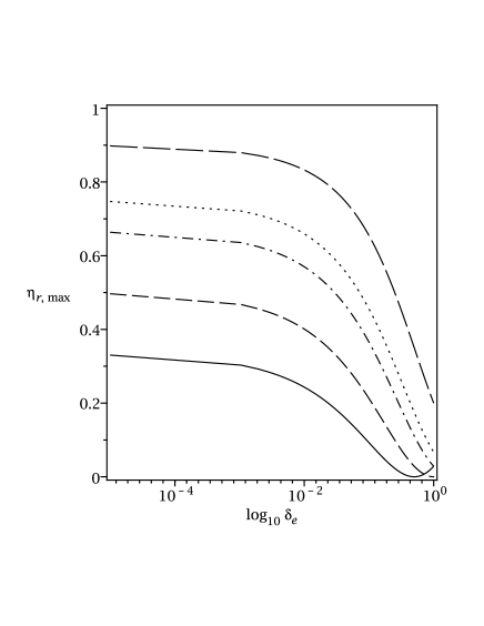
This simple analysis hints that the radiative efficiency of impulsive magnetically dominated flows can be very high. Moreover, the outcome does not even depend on the magnetization. Other important properties of the process however may do. For example the rate of dissipation, and hence the luminosity. In order to investigate this issue a bit further we have carried out numerical simulations.
| X | 30 | 1 | 30 | 15 | 0.5 | 3.5 | |||
| A | 5 | 1.0 | 1 | 5 | 1 | 3 | 1.8 | 0.13 | 3.9 |
| B | 15 | 3.0 | 1 | 5 | 1 | 9 | 5.4 | 0.13 | 8.3 |
| C | 15 | 0.1 | 3 | 150 | 1 | 7.6 | 2.1 | 0.68 | 1.6 |
| D | 30 | 0.1 | 1 | 300 | 1 | 15. | 7.9 | 0.44 | 4.2 |
| E | 30 | 0.1 | 1 | 30 | 10 | 2.8 | 1.6 | 0.32 | 1.6 |
| F | 30 | 1.0 | 1 | 30 | 1 | 16. | 8.9 | 0.32 | 5.62 |
| G | 30 | 0.1 | 3 | 300 | 1 | 15. | 4.1 | 0.70 | 2.2 |
| H | 30 | 1.0 | 3 | 30 | 1 | 16. | 4.9 | 0.58 | 3.6 |
3.2 Numerical simulations


We solve numerically the one dimensional equations of single-fluid relativistic magnetohydrodynamics in plane (or slab) geometry. In order to account for the radiative cooling we introduce a source term in the energy-momentum equation:
| (20) |
where is the stress-energy-momentum tensor of fluid, is its 4-velocity, and is the cooling rate as measured in the fluid frame. The cooling rate used in our simulations is not based on any particular physical mechanism. At this stage, it makes sense only to require for the cooling time to be short compared to the dynamical time scale, as this seems to be required by the observations of GRBs. To be specific, we put
| (21) |
where is the “temperature”
and is the characteristic cooling time. In the simulations we used and , a small fraction of the chamber light crossing time. This cooling function implies that all particles cool rapidly and this may be rather unrealistic, as only relativistic electrons radiate efficiently. However, we do not expect this to change the results by more than a factor of few because the ’thermal pump’ mechanism (Kobayashi & Sari, 2001) is likely to be efficient in re-processing the retained thermal energy. The equation of state describes an ideal gas with the adiabatic index .
The numerical scheme is based on the one described in Komissarov (1999), with few improvements added over the years. The computational grid is uniform with 600 cells. Because of the presence of strong shocks in the solution the scheme is only of the first order accuracy. Our convergence study shows that the typical computational error for most of the parameters discussed below is about few percents.
The units are selected in such a way that the dimensionless chamber length is and the speed of light is . The pulse is initially located in the middle of the chamber. The transition from the pulse to the gap state is smoothed out using the function, with the width of the transition layer .
Table 1 shows the parameters of all models we present here. Following the reasons behind the magnetic pump mechanism, the magnetization parameter of the pulse, , is always high, varying between 5 and 30. The gap magnetization is normally much lower, , but we also included the cases where is above unity. In all cases, the total energy of the initial state is dominated by the magnetic field, corresponding to .


We first discuss the model X, where the gap is basically empty, as this is the closest case to the scenario envisioned in Granot et al. (2010). Figure 4 illustrates the flow dynamics in this model. The first column shows the solution at , when the pulse is beginning to expand for the first time. In both halves of the chamber, the solution exhibits a rarefaction wave, moving into the pulse and ejecting its plasma into the gap. The ejected plasma expands into the gap space and develops very high velocity. In fact, it can reach when the gap is a pure vacuum (Lyutikov, 2010; Granot et al., 2010), but in our simulation it is limited by the numerical resolution and the non-vanishing density of the gap plasma.
The second column shows the solution at , soon after the collision of the flow with the chamber walls, which drives strong shock waves back into the pulse. One can see that behind the shocks both the magnetic pressure and the plasma magnetization are almost as high as initially in the pulse. The gas passed through the shock is heated to a very high temperature and its cooling rate reaches maximum. On the contrary, in the initial location of the pulse a secondary gap is forming behind the two rarefaction waves which have now been reflected off the centre. The gap and the pulse have switched their places almost recreating the initial conditions.
The third column shows the solution at , soon after the reflected shocks have collided in the center of the chamber for the first time. One can see that a region of high magnetic pressure and is formed in the original location of the pulse. This “born again” pulse drives the next round of expansion and shock heating.
The forth column of Figure (4) shows the solution at , which is separated from the solution presented in the first column by exactly one light crossing time of the chamber. Qualitatively, the solutions look very similar, but at the gap is no longer empty and the pulse expansion drives a shock through its plasma. This is why the Lorentz factor is so much lower.
Figure 5 shows for comparison the solution for the model D, where the gap is filled with a significant amount of plasma from the start. One can see that there is a strong similarity between models D and X. The first column shows the solution at , when the pulse is beginning to expand and compress the gap plasma for the first time. In both halves of the chamber the solution exhibits a rarefaction wave, moving into the pulse, and a shock wave, moving into the gap. At the shock, the plasma is heated and then it rapidly cools. An insignificant heating is also seen in the middle of the rarefaction wave, where the velocity gradient is the highest. This heating is entirely due to the numerical viscosity, and represents computational errors. The second column shows the solution at , soon after the shocks reflection off the chamber walls. By this point the gap plasma has been shocked twice, first by the incident and then by the reflected shock. It’s temperature and the cooling rate are reaching maximum. By , the reflected shocks have collided in the center of the chamber for the first time and the “born again” pulse drives the next round of expansion and shock heating. When the shocks reflect of the walls again (see the fourth column of Figure 5) the solution is very similar to that at the time of the first reflection. Thus, the system is undergoing strong oscillations and the gap plasma experiences repeated shock-heating.
Figure 6 shows the integral rate of radiative cooling for all our models, except G. These curves exhibit strong peaks at the time of the shock collisions at the walls and in the middle of the chamber, as this is the time when the shocks cross plasma with lower magnetization. In model X, the amplitude of the peaks decreases with time monotonically. This reflects the fact that in this models the gaps developing in the centre of the chamber have very similar parameters to those developing at the walls. The overall decrease of the cooling rate is caused by the gradual decrease of the shock strength and increase of the gap magnetisation. In all other models, peaks corresponding to the shock collision with the wall are significantly stronger than those corresponding to the shock collisions in the middle of the chamber. This is because the gaps are filled with weakly magnetised plasma from the start.
These peaks are strongest for models C,D,E and G, which have lower gap magnetization, , and much weaker in models A,B,F, and H which have higher gap magnetization, . The integral radiative cooling rate of models with higher gap magnetization is also much lower and it declines slower. This is fully consistent with lower energy dissipation rate in the case of higher magnetization, as explained in Section 2, and with the fact that the overall radiative efficiency does not depend on the magnetization (see Section 3).

Figure 7 shows the total energy radiated by the time . It confirms that even models with high gap magnetization eventually approach the efficiency given by Eq.18, this only takes a bit longer. The last column of Table 1 gives the time required for the system to radiate 50% of , the total amount of energy which will be eventually lost. It spans from one to ten chamber light crossing times, increasing as expected with the gap magnetization. It is interesting that the model X is not much different from models, in spite of the lack of weakly magnetized plasma in the initial state. The explanation for this seems to reside in the ability of strong rarefaction waves to supply such plasma and provide it with much higher fraction of the kinetic energy compared to the rest of the flow (Granot et al., 2010). This agrees with the fact that faster dissipation is found in the models C and G, which have three times wider initial gaps, thus allowing a larger fraction of the ejected pulse plasma to develop low and high . The model E also shows faster dissipation. This is due to the fact that its initial gap, which is already weakly magnetized (), is ten times more massive compared to other models.
4 Adiabatic flow


Although suggesting many interesting hints, the chamber problem may differ from the case of impulsive flow in many respects. For example, in this problem all of the released magnetic energy is converted into radiation. This can not be so in the case of a flow, where not only energy but also momentum is associated with the electromagnetic field of pulses. Some of this momentum can be passed on to plasma, resulting in its bulk acceleration. Considering the dynamics of an isolated pulse, Granot et al. (2010) have found that the pulse develops a very fast “head” and that most of the pulse magnetic energy is converted into the bulk motion kinetic energy of this head. In principle, interaction between pulses may change this outcome. Analysing this issue, Granot et al. (2010) pointed out that the head does not spread much until its acceleration is over and argued that because of this the collisional interaction between individual pulses is delayed until the end of their acceleration phase. However, each pulse also develops a long slow tail and even if the gaps between pulses are completely evacuated initially they quickly become filled with the plasma of these tails. The shock interaction between the heads and the tails may modify the flow dynamics.
The easiest way to address this issue is to consider a periodic train of identical traveling pulses separated by empty gaps. As the pulses interact and the shocks dissipate the kinetic energy of relative motion, the flow gradually approaches a state with uniform total pressure. Provided the radiative cooling is negligible, the parameters of this state can be found analytically from the equations of mass, magnetic flux, energy, and momentum conservation.
4.1 Asymptotic state
These conservation laws are
| (22) |
| (23) |
| (24) |
| (25) |
where is the relativistic enthalpy, , where is the adiabatic index, and are the magnetic field and the plasma speed as measured in the observer frame. Here, the expressions of the type stand for the difference between the final and the initial value of . That is , where the index “0” corresponds to the initial state and the index “1” to the final state. For the initial state is the pulse width, whereas for the final state is the wavelength of this periodic configuration, as measured in the observer frame.
Denoting the cell mass and magnetic flux as and , the equations of energy and momentum can be written as
| (26) |
| (27) |
These equations are to be solved for the thermodynamic pressure, , and the Lorentz factor, , of the final state. Subtracting them and using the approximation , one finds
| (28) |
Since this yields
| (29) |
Next one can simplify Eq.27 by putting , which gives
| (30) |
Elimination of from this equation leads to the quadratic equation
| (31) |
where , , and . This equation has only one physical solution
| (32) |
where . It easy to see that and thus the flow is accelerated. The corresponding increase of the bulk kinetic energy is
| (33) |
whereas the released thermal energy is
| (34) |
both quantities being normalised to the initial magnetic energy, .
For , which implies high initial magnetization and not very narrow gaps, one has
| (35) |
Thus , which is significantly lower compared to , corresponding to the total conversion of magnetic energy into the kinetic one. Hence most of the magnetic energy must be converted into heat. Indeed, from Eqs.(33) and (34) one has
| (36) |

4.2 Numerical simulations
In these simulations, we utilise the spatial grid which moves relative to the inertial frame of our fiducial observer with the initial speed of the pulse. This is similar to the so-called “moving window” approach. Namely, we use the time-like foliation of space-time defined by the time of observer’s inertial frame, but introduce new spatial coordinate via the transformation . This leads to the metric form
| (37) |
The computational domain covers one wavelength of the flow and the initial solution describes a uniform pulse located right in the middle of this domain. The gaps are not absolutely empty but they are so highly rarefied and weakly magnetized that have very little effect on the solution. The initial Lorentz factor is uniform throughout the domain. Both at the left and the right boundaries we impose the periodic boundary conditions.
Figure 8 illustrates the typical evolution of such a flow. In this particular model, the initial magnetization of the pulse is , its thermal pressure is negligibly small, and it moves with the Lorentz factor to the right. The flow is super fast magnetosonic, with the Mach number . The pulse () and the gap are equal in linear size, with . The ratio of specific heat is again ( and ).
At the solution is very much as this was anticipated in Granot et al. (2010). Indeed, it is dominated by two strong rarefaction waves, both originated at the pulse boundaries and moving inside the pulse. However, the one produced at the head propagates through the pulse much faster than the one produced at the tail. As the result, inside most of the pulse the magnetic pressure declines towards the head and the magnetic pressure force accelerates the flow. The other rarefaction gets stuck at the back where it ejects pulse plasma into the tail, which grows in size almost at the speed of light. By the tip of the tail has already crossed the gap and collided with head (of the other pulse). Two shock waves, one forward and one reversed, are produced as result of this collision, they are responsible for the spike observed at .


At the solution already looks rather different from that of an isolated pulse. The reverse shock has moved well inside the pulse and it is now located at . Behind the shock, the flow has almost recovered its initial Lorentz factor, magnetization , and magnetic pressure.
By all the features of the strong rarefaction wave, characteristic for the isolated shell solution, have gone. Now the solution can be broadly described as a flat-top pulse with a tail.
Due to the periodic boundary conditions, when a wave reaches one boundary it re-appears from the other one. The forward and reverse waves do this at a very different rate. Indeed, if the wave Lorentz factor in the flow frame is and the flow Lorentz factor then the observed relative speed of the forward wave is
| (38) |
whereas for the reverse wave we have
| (39) |
which is much faster. This difference must be behind the observed much more rapid decay of reverse waves compared to forward waves. As one can see in Figure 8, at the amplitude of forward waves is much higher and the flow exhibits the characteristic “saw-tooth” profile similar to the one which develops in the problem of nonlinear wave steepening.
Figure 9 illustrates the energy evolution of the flow. It shows the variations of the magnetic, bulk motion, and thermal energies per train wavelength, all being normalised to the initial magnetic energy. Since, in this problem , by the time the system relaxes to a uniform state its magnetic energy decreases by 50 percent. As one can see in Figure 9, this has almost been achieved at . According to the analysis of Sec.4.1, the asymptotic parameters of this flow are , and . These are indeed very close to the values observed at (see Figures 9 and 8).
The characteristic time of relaxation towards the uniform state must be given by the dissipation time scale of the forward waves associated with the saw-tooth structure of the flow. First, the pulse has to pass through the forward fast shock where the dissipation occurs. Given the result (38), the corresponding time, , is actually independent on the shock speed, and hence its strength. Second, each time when a strong shock crosses the pulse it dissipates only a fraction of the available pulse energy (see Eq.12). Thus, the relaxation time can be estimated as
| (40) |
This turns out to be about the same as the time scale of the nonlinear steepening of a fast magnetosonic wave (see Eq.11 in Lyubarsky, 2003). For our numerical model, , if we use the parameters of the initial solution for the calculations, in excellent agreement with the numerical results.
4.3 Comments on the geometrical effects
The results of our study show that the interaction between individual pulses (magnetic shells) becomes important well before the coasting phase of an isolated pulse, significantly reducing the efficiency of impulsive acceleration. However, the dynamics of adiabatic flows is strongly influenced by their geometry. For example, the sideways expansion of conical jets is an efficient way of converting their thermal energy into the kinetic energy of bulk motion. Thus, provided the radiative cooling time is long compared to the adiabatic one, a conical flow can still eventually become kinetic energy dominated. In the context of the pulsar wind acceleration this mechanism has been discussed in Lyubarsky (2003).


In order to find the asymptotic flow parameters in this case we simply notice that because
| (41) |
the kinetic energy
| (42) |
Thus, the asymptotic magnetization parameter should be
| (43) |
We comment here that unless the gap is much wider than the pulse, and hence is very close to unity, the asymptotic magnetization is still not much lower than unity. For example, when , and hence , this equation gives . Eqs.(22) and (23) give us another expression for , namely
| (44) |
Combining the last two equations we find the asymptotic Lorentz factor
| (45) |
Although in this case we almost recover the asymptotic parameters of isolated shells (Granot et al., 2010), the acceleration mechanism is different. Indeed, the key role is played by the shock heating and thermal acceleration, instead of the magnetic pressure acceleration. Moreover, in the context of GRBs, this regime is not very attractive because it implies low radiative efficiency. Indeed, by the time the flow becomes kinetic energy dominated, its impulsive origin is “washed out”, with the remaining shock waves being week and allowing dissipation of only a small fraction of the flow power.
5 Radiatively cooling flow
On the opposite extreme to the adiabatic flow is the case where the radiative cooling time scale is much shorter compared to the time scale of adiabatic cooling. This is the so-called “fast radiative cooling” regime, which has been often discussed in connection to GRB jets. In this case the difference between the plane and spherical geometry is unimportant as all of the released thermal energy is lost to the radiation. Assuming that the total fraction of the utilised magnetic energy is the same as in the adiabatic regime, one would expect very high radiative efficiency,
| (46) |
In fact, this is the same as in the chamber problem with empty gaps (see Eq.19). However, both the radiative cooling and the radiation reaction force may modify the flow dynamics and in this Section we investigate their roles.


5.1 Asymptotic state
In this case, one can still try to determine the asymptotic flow parameters using the conservation laws, just like this was done in Sec.4. While the mass and the magnetic flux conservation laws remain the same, the laws for energy and momentum have to be modified in order to account for the radiative losses:
| (47) |
| (48) |
Here we use the fact that the total energy-momentum of emitted photons can be written as (see Eq.20), where is the averaged 4-velocity of the flow during its relaxation. Its value depends on possible correlation between the rate of radiative losses and the flow speed, e.g. the radiation may come mostly from the fastest parts of the flow. Since this is essentially an unknown parameter, we end up with an under-determined system, which has only four equations and five unknowns, namely , , , , and .
Eliminating , , , and using the usual high speed approximation , we find the equation determining as a function of ,
| (49) |
If we put then this equation yields
| (50) |
where the last step assumes . This is indeed very similar to what we have found in the adiabatic case in the slab geometry (see Eq.35).
On the other hand, when , we have
| (51) |
This implies very efficient flow acceleration with almost total conversion of magnetic energy into the bulk motion kinetic energy for , contrary to what we have anticipated. The reason for this is the strong radiation reaction force, which accelerates the flow. Indeed, implies that most of the time is lower compared to the center-of-momentum Lorentz factor. Because of this, in the centre-of-momentum frame, the photons are emitted mostly in the direction opposite to the flow direction. This seems hardly possible as most of the radiation must come from the immediate downstream of forward shocks and if the flow preserves the structure of adiabatic solution then these are the fastest sections of the flow (see Figure 8). In fact, this argument suggests that the asymptotic Lorentz factor can be quite close to that given by Eq.50. In order to verify this deduction we have carried the numerical simulations described below.
5.2 Numerical simulations
In these simulations we used the same cooling function as in the chamber problem (see Eq.21). In order for the numerical shock structure not to have much influence on the overall effect of radiative cooling, we had to insure that the cooling length scale was significantly higher compared to the shock thickness. If the proper cooling time scale is then in the observer frame this scale is . In this time, a weak forward magnetosonic shock wave moves relative to the flow by the observed distance . Thus in order for the length of the cooling region behind the shock to be a fraction of the flow wavelength, the proper cooling time should be . In these simulations we used .
First we studied the model with the same initial parameters as the adiabatic one described in Section 4: , , , and . Overall, the cooling flow shows a similar deviation from the dynamics of isolated pulse, considered in Granot et al. (2010), as the adiabatic model. Figure 10 compares the adiabatic and cooling flows at later times. As one can see, both flows develop the characteristic “saw-tooth” profiles and apart from the temperature, their parameters are rather similar. The cooling flow is only slightly faster compared to the adiabatic one.

The left panel of Figure 11 compares the energy balance of both flows. It confirms that the cooling flow is slightly more efficient in converting the magnetic energy into the bulk kinetic energy. It also shows that by most of the free magnetic energy has been utilized. Comparing the numerical results with the predicted asymptotic parameters of the cooling flow (see Sec.5.1), we find that Eq.50 does better, with , whereas Eq.51 significantly overestimates the asymptotic Lorentz factor, giving . Figure 10 shows that most of the radiative energy losses are associated with the fastest parts of the flow, just like we have anticipated, and this explains why Eq.50 provides a more accurate estimate.
The right panel of Figure 11 compares the energy budgets of three cooling models which differ only by the Lorentz factor of the initial solution, and 10. One can see that the efficiency of magnetic acceleration grows with , but only slightly. In all these models, more than half of the free magnetic energy is converted into radiation. Supported by the strong arguments presented in Sec.5.1, we conclude that when most of the released magnetic energy is converted into radiation, and the radiative efficiency can indeed be estimated using Eq.46.
6 Radiatively cooling flow with filled gaps


Finally, we investigate a flow with fast radiative cooling and gaps filled with low magnetised plasma from the start. Provided the initial state has the same Lorentz factor both for the gap and the pulse, the fraction of released magnetic energy is the same as in the chamber problem (see Eq.18)
| (52) |
This energy is converted partly into the radiation and partly into the bulk kinetic energy. Although this partition is difficult to estimate analytically, there are no obvious factors that could significantly shift the balance in favour of the kinetic energy, suggesting that most of the magnetic energy should still be converted into the radiation. This is confirmed by numerical simulations
Here we present the results for the model with parameters , , , , and . For this parameters Eq.52 gives . The left panel of Fig.12 compares the energy balance of this model with the empty gap model which has the same pulse parameters and hence . As one can see, in both these models the released magnetic energy does evolve towards the predicted asymptotic values and at approximately the same rate. The partition of this energy between the bulk kinetic energy and the radiation is also similar. This allows us to conclude that in the case of energetically subdominant gaps, the radiative efficiency is similar to what we have for empty gaps, and is well described by
| (53) |
Because the total accelerated mass is twice as higher in the model with filled gaps, one would expect the asymptotic Lorentz factor in this model to be lower compared the corresponding model with empty gaps. The data presented in Fig.13 and Fig.10 show that this is indeed the case. However, the difference is rather small, and this suggests that the asymptotic Lorentz factor is still well described by Eq.50 when the gap mass does not exceed that of the pulse.
The energy curves shown in the left panel of Fig.12 are more ragged for the model with filled gaps. Moreover, their structure suggests a quasi-periodic process. In fact, the curve of radiated energy is similar in shape to those found in the chamber problem, indicating a strong variation of the dissipation rate. This is confirmed by the left panel of Fig.12, which shows the energy loss rate. Just like in the chamber problem, one would expect its spikes to be associated with crossings of weakly magnetised gaps by shocks. This is indeed the case, as illustrated in Fig.14. This plot also shows that, like in other models, the flow develops the characteristic saw-tooth profile. The time separation between these spikes can be explained using Eq.38. According to it, the pulse crossing time by a relativistic forward wave is , where we used . This is indeed very close to the spike separation in Fig.12. The rapid variability inside the first spike is connected to the reverse shock, which crosses the shell much faster (see Eq.39).
7 Discussion
7.1 Dynamics of impulsive magnetically-dominated outflows
In recent years a great deal of progress has been achieved in the dynamics of magnetic steady-state flows but the observations seem to suggest that the central engines of cosmic jets are highly variable. Is this variability only a minor complication or it can actually lead to a qualitatively different jet dynamics? The recent pioneering studies of this issue have suggested the latter (Contopoulos, 1995; Granot et al., 2010; Lyutikov, 2010; Lyutikov & Lister, 2010; Lyutikov, 2011). However, they were mainly concerned with the dynamics of individual shells, presumably ejected by the central engine, and their interaction with the external medium. These issues were studying using rigorous mathematical modelling. On the contrary, the problem of interaction between magnetically accelerated shells has remained until now a subject of only rather speculative semi-quantitative analysis. One of the main objectives of our study was to explore this important issue a bit further.
One of the most important properties of the isolated shell solution is the concentration of energy and momentum in the compact head of the shell formed by the reverse rarefaction wave early on (Granot et al., 2010). This rarefaction wave can be seen in the plots of the left column of Figure 8, where it occupies the domain . The head formation is completed when this rarefaction reaches the back of the shell and gets reflected as a forward rarefaction. The part of the shell located between the leading interface with vacuum and the leading front of the reflected rarefaction wave is what constitutes the shell head. In the source frame, it shows very little spreading in the direction of motion and its mean Lorentz factor increases as .
Granot et al. (2010) and Granot (2011b) argued that this somewhat unusual, but well understood in the relativistic framework, behaviour of the shell head allows us to ignore the interaction between individual shells until their Poynting flux is almost fully converted into the bulk motion kinetic energy. Only after this, during the coasting phase, the shell spreading becomes important and leads to strong collisions between shells, thus allowing internal shocks with high dissipation efficiency. This assertion had apparently given a great importance to the assumption, made in that study, that the gaps between shells were empty, or at least so highly rarefied that their plasma could not influence the shell dynamics. In fact, the authors overlooked the ejection of shell plasma into its tail, which would rapidly fills the gap, and did not explore the possible implications of the head-tail collision for the shell dynamics.
An isolated shell enters the coasting phase at , where is the asymptotic Lorentz factor of the shell (Granot et al., 2010). This is the time required for a fast magnetosonic wave moving relative to the shell head with the observed speed (see Eq.38) to traverse the head. The relative observed speed at which the shell plasma is ejected into the tail can be estimated via Eq.39, which gives us . Thus, one can avoid the head-tail collision only if the gaps between shells are much wider than the shells.
Our simulations have shown that, at least in the case there shells and gaps have comparable widths, the tail-head collision strongly modifies the flow dynamics, making the results for an isolated shell irrelevant. The gaps soon become filled up with significant amounts of plasma, and thereafter we have what is best described as a continuous inhomogeneous flow superimposed with a wave train. A similar outcome is observed when the gaps are filled with plasma already from the start. The subsequent acceleration and radiation of this flow is determined by the dissipation rate of shocks, which form an integral part of the train, the plasma cooling rates, and the flow geometry. In any case, the fraction of magnetic energy that can be converted into either the energy of radiation or the kinetic energy of the flow is set by the energy of the train. Under the condition of magnetic flux freezing, it is simply given by the degree of expansion in the longitudinal direction which the magnetised shells can achieve during the transition to force equilibrium and thus by the amplitude of initial fluctuations of magnetic pressure.
When the radiative cooling can be ignored, the asymptotic flow parameters follow from the basic conservation laws of mass, magnetic flux, energy, and momentum. This way we find that in the case of slab geometry, the asymptotic Lorentz factor is , rather than expected in the case of the total conversion of the magnetic energy into the bulk motion kinetic energy (Here is the relative thickness of the gap .). In contrast to the case of an isolated pulse Granot et al. (2010), the magnetic acceleration is inefficient and most of the free magnetic energy is converted into the thermal energy via the shock dissipation. However in the case of spherical geometry, the sideways expansion of the flow is accompanied by efficient conversion of this thermal energy into the bulk kinetic energy, via the thermal acceleration mechanism. This leads to the asymptotic Lorentz factor .
When the radiative cooling is much faster than the adiabatic one, the difference between flows with slab and spherical geometry is unlikely to be significant, although the presence of poorly radiating components such as protons complicates this issue and requires further investigation. Even without such components, the fast cooling regime is more involved as the conservation laws alone do not determine the asymptotic flow parameters. The outcome now depends on details of the radiative cooling process. The radiation reaction force may both help the flow acceleration and make it more difficult, depending on whether the photons are emitted predominantly in the forward direction in the centre-of-momentum frame or in the backward direction. From the numerical simulations we find that the emission comes from the fastest part of the flow and thus the radiation reaction force is a decelerating one. Most of the utilised magnetic energy is converted into the radiation and the asymptotic Lorentz factor of the flow remains significantly below the value of , characteristic of efficient magnetic acceleration.
7.2 Astrophysical implications
In terms of astrophysical implications, our results are most relevant to the issue of internal shock dissipation and emission from relativistic jets of GRBs and AGN. A detailed test of the shock dissipation model in magnetically-dominated flows against observations is beyond the scope of this paper. Here we only outline few issues to be investigated in future studies.
Just like in the hydrodynamic model, the energy reservoir for the internal shock dissipation in the magnetic model is associated with the variable component of the jet. For Poynting-dominated jets this is the magnetic energy of the fast magnetosonic waves driven into the jet by the variable central engine. Their contribution to the overall jet energy budget depends on the exact details of the central engine operation, and at least in principal it may well be dominant.
Provided the radiative cooling time is sufficiently short, most of the dissipated energy is converted into radiation. In our simplified test problems, the radiative efficiency is given by the Equation 18, which shows that it can be very substantial even for a rather moderate central engine variability. Thus as far as the observed radiative efficiency of GRB jets is concerned, the internal shock model of prompt GRB emission and the magnetically-dominated model of GRB jets are not mutually excluding. However, the dissipation length scale increases with the jet magnetization and may exceed the jet length.
In the hydrodynamical version of the internal shock model, the prompt emission originates from the region where individual ballistic shells collide with each other because of the differences in the ejection speed (Piran, 2004). For strong variation of the Lorentz factor, this occurs at
| (54) |
where is the characteristic time interval between the shell ejections111Such a characteristic time does not have to exist. Instead, the central engine may exhibit a wide distribution for the shell ejection time., and is the Lorentz factor of the slower shell. Each collision gives rise to a pulse of the prompt emission light-curve. Its duration, , is determined by the curvature of the shock front and the Doppler beaming (the so-called “angular spreading effect”), and it turns out to be the same as (Piran, 2004).
In the magnetic model, the prompt emitting region can extend well beyond . According to Eq.40 a forward shock dissipates its energy when it covers the distance . For s, is already dangerously close to the radius of the external shock which seems to rule out . However, the problem arises only if we associate each strong individual pulse of a GRB light curve with an individual shock wave. If instead each such pulse is associated with a whole packet of shocks, so that , this is no longer an issue. Obviously, this explanation implies a secondary central engine variability process, operating on the time , which modulates the output of the primary process, operating on the timescale . In fact, this way one can explain why about of GRBs have rather featureless light curves (Piran, 2004). This may just be the case of weak modulation.
In this model, there are shocks inside the dissipation zone and one may wonder if their emission signals overlap. In the source frame the relative speed of a light signal and a forward fast magnetosonic wave propagating in the radial direction is
| (55) |
The travel time across the dissipation zone is . During this time the distance between these two waves is changed by only . Thus, the overlapping could only be a result of the angular spreading effect, which spreads -shape signals over the time , where is the emission radius. This gives us at the beginning of the dissipation zone () and at the end of the dissipation zone (). One may draw two conclusions from these numbers. First, a micro-pulse from an individual shock must have a long smooth tail of length . Spike-like features on the scale of can be found only at the head of this micro-pulse (They may correspond to shock crossings of contact discontinuities in the jet; see Fig.6 and Fig.11). Second, the tails of individual micro-pulses overlap but their leading spikes do not and can give rise to a pulse substructure. The fact that, shocks are strongest at the beginning of the dissipation zone increases chances of them being detected. This could be the origin of the observed variability of GRBs on millisecond time scale (Walker & Schaefer, 2000).
How short can be? In the Blandford-Znajek model of GRB central engine, the only “easy” way of changing its jet power, , is via changing the flux of open magnetic field lines, , which threads the black hole, as these parameters relate via (Blandford & Znajek, 1977). This magnetic flux may change significantly if the disk drags in an alternating magnetic field, which may even bring about a change of polarity of the black hole magnetosphere222 The effective loss of magnetosphere and its shielding action during a change of polarity may also let weakly magnetized surrounding plasma to enter the jet channel and to become entrained by the jet.. The relevant time scale for this process is probably the disk inner edge “viscous” time scale. For an -disk, this is
| (56) |
where is the black hole mass and is the ratio of the disk height to its radius (Shakura & Sunyaev, 1973). This is almost a hundred times shorter compared to the observed typical separation between GRB pulses (Norris et al., 1996). horizon. The shortest scale for restructuring of the black hole magnetosphere is given by the light crossing time of the ergosphere
| (57) |
A rapid and frequent restructuring of magnetosphere may also be typical for a newly-born millisecond magnetar, due to its ultra-strong magnetic field, lack of solid crust, and active magnetic dynamo. These estimates assume fast magnetic reconnection in the magnetospheres, which has been questioned recently on the basis of collisional nature of reconnection of super-strong magnetic field (McKinney & Uzdensky, 2010; Lyutikov & McKinney, 2011; Uzdensky, 2011), although even the collisional magnetic reconnection can be fast due to the secondary tearing instability (see the discussion and references in Uzdensky, 2011).
As to the modulation process, it should also involve variation of but on a larger time scale. For example, more massive accretion disks could support stronger magnetic field and result in larger magnetic flux trapped by the black hole. Variations of the disk mass could result from unsteady stellar collapse. The typical duration of strong GRB pulses is around the free-fall time from the radius of cm for the GRB progenitor in the collapsar model. Given the total radius of the progenitor, , it does not seem implausible for the GRB jet to perturb the stellar mass distribution on this scale.
Swift observations of early X-ray afterglows have discovered the presence of plateaus as well as strong flares in their light-curves, both unexpected in the original external shock model (Zhang, 2007b). One possible and perhaps the most likely explanation of these features is that they represent the “late prompt emission” of a long-lasting central engine (Ghisellini et al., 2007, 2009). This interpretation is supported by a number of similarities between the X-ray flares and the GRB sub-pulses (Margutti et al., 2010). Such a long-lasting activity, at least up to seconds, is inconsistent with the high mass accretion rate, above s, required by the neutrino annihilation mechanism of jet production and implies the magnetic mechanism.
In addition to the similarities between the X-ray flares and the GRB sub-pulses, there are also few differences (Margutti et al., 2010). For example, the flare duration increases linearly with the flare time since GRB trigger. In our model, the duration of prompt pulses is determined by the duration of strong accretion episodes in the history of the central engine. If the X-ray flares are associated with the fallback accretion, then the flare time is likely to be determined by the location of fallback turning point whereas its duration by the spatial dispersion of falling back material. They may well correlate with each other.
The evolution of individual pulses of GRBs is often described as “Fast Rise Exponential Decay” (FRED, e.g. Piran, 2004). The latest results show that on average both the prompt pulses and the X-ray flares have approximately twice as shorter the rise time compared to the decay time (Norris et al., 2005; Chincarini et al., 2010). Although shorter rise times are expected in the standard internal shock model, it does not really say by how much (Yi-Ping Qin et al., 2004). Perhaps, this tells us that the pulse shape is not determined by the shell collision after all. Other processes may have similar time properties. In fact, FRED mass accretion rate could be a general consequence of the diffusive transport in episodic accretion disks (Wood et al., 2001).
We have shown that, provided the GRB jets are cooled mainly radiatively, they are likely to remain Poynting-dominated even beyond the prompt emission zone. The exact nature of piston driving the external shock into the surroundings of GRB has little effect on the shock dynamics and emission. Provided the total energetics is the same, both the kinetic energy dominated and the magnetic energy dominated ejecta produce the same afterglow emission associated with this shock (Lyutikov & Blandford, 2003; Lyutikov, 2005, 2011; Mimica et al., 2009). However, the reverse shock, which is driven into the ejecta, will be much less dissipative if the ejecta is highly magnetized (Zhang & Kobayashi, 2005; Mimica et al., 2009). This could be the reason behind the paucity of the lower energy, most likely optical, flashes expected from the reverse shock in the non-magnetic models of afterglows (Gomboc et al., 2009).
As to the issue of the jet acceleration, our results indicate that the impulsive magnetic acceleration mechanism, proposed by Granot et al. (2010), is unlikely to operate in its original form. Even if we ignore the entrainment of surrounding plasma, the strong shock interaction between heads and tails of magnetic shells, revealed in the present study, is already sufficient to prevent the conversion of almost all available magnetic energy into the kinetic energy shell heads. Instead, the problem reduces to its more standard form where non-linear waves travel along the jet, interacting with the mean flow. The efficiency of the mean flow acceleration by these waves depends on the efficiency of its radiative cooling, and hence on the photon opacity of the flow. If this cooling is weak then the jet acceleration can be very efficient, with a large fraction of the wave Poynting flux converted into the kinetic energy of the flow. Otherwise, it is converted into radiation. Based only on baryonic electrons the optical thickness of a GRB jet to Thomson scattering is
| (58) |
where is the isotropic jet power. Thus, it seems unlikely for the dissipation zone to be optically thick, unless pairs dominate the opacity. This agrees with the high observed radiative efficiency of GRB jets.
Impulsive jet production provides favourable conditions for entrainment of weakly magnetised plasma that may exist in the vicinity of the central engine. We focused on the implications of this process for the dissipation efficiency of shock waves in magnetically dominated flows. But in addition to this, the presence of weakly magnetised plasma may also help to overcome another difficulty of the shock model, related to the shock acceleration of non-thermal particles. However, for this to work the magnetization may have to be very low, down to (Sironi & Spitkovsky, 2010).
8 Conclusions
In this paper we analysed the potential role of shock dissipation on the dynamics and emission of impulsive Poynting-dominated relativistic jets. The main insights came from analytical and numerical solutions of Relativistic MHD equations in slab geometry. For computational reasons the numerical simulations were limited to flows with Lorentz factors which were much lower compared to those deduced from the observations of GRBs. These and other limitations of this study warn against making firm conclusions and a certain degree of uncertainty definitely remains in many respects, and particularly when it comes to astrophysical applications. Keeping this in mind, our main conclusions are
-
•
The dissipation efficiency of strong shocks in highly magnetized plasma is low , mainly because only the kinetic energy dissipates and it represents only a small fraction of the total energy flowing through the shock. For moderate magnetization, , the shock dissipation efficiency is reasonably high, % of the total energy flux.
-
•
The dynamics of a magnetic shell in a train of shells, all ejected in the same direction and initially separated by empty space, can be rather different from that of an isolated shell in vacuum, studied in Granot et al. (2010). Unless the separation between these shells is very large, they strongly interact with each other. The result of this interaction is best described as an underlying continuous flow superimposed with strong magnetosonic waves travelling in the same direction. The wave Poynting flux provides energy for heating and acceleration of the flow. A similar outcome is observed in models where gaps are filled with energetically sub-dominant plasma from the very beginning.
-
•
For an infinite flow, the reservoir of magnetic energy is given simply by the decrease of the magnetic energy, as dictated by the magnetic flux freezing, during the transition to a wave-free final state. The shock dissipation is an essential part of this transition. The radiative cooling allows to maximise the released magnetic energy. For radially diverging flows, the adiabatic cooling is expected to do the same. In both cases, the fraction of released magnetic energy does not depend on the initial flow magnetization but only on the initial magnetic inhomogeneity of the flow, or in other words on the fraction of energy carried by the waves. However, the flow magnetization determines the tempo and the characteristic length scale of the energy release, which grows for .
-
•
With application to GRB jets, this shows that the internal shocks may still be responsible for the prompt emission even in the case of Poynting-dominated jets. At least, the high observed fraction of the prompt emission in the total energy budget of GRB events is not inconsistent with this model.
-
•
However, the increased size of the prompt emission (internal shock dissipation) zone, compared to that of the non-magnetic model, calls for a somewhat different interpretation of the prompt emission variability. In particular, the observed individual pulses with duration around one second are unlikely to be associated with the emission of individual shocks, as this would push the dissipation zone beyond the external shock radius. Instead, each such relatively long pulse could represent the combined emission from a whole pack of shocks associated with mini-shells ejected by the central engine on a much shorter timescale. The long timescale variability would then be related to some modulation process, determining the energy of emitted mini-shells. In fact, both the magnetar and black hole magnetospheres do allow variability on millisecond, and possibly even shorter, timescales. As to the nature of the modulation, one possible mechanism is the unsteady mass supply to the accretion disk in the collapsar scenario.
-
•
The emission from individual shocks may produce fine substructure, on the timescale of shell ejection. This could be the origin of the observed millisecond spikes in the light-curves of the prompt emission.
-
•
After leaving the zone of internal dissipation, the initially Poynting-dominated jet is most likely to remain Poynting-dominated. This may not effect the dynamics of the forward shock and its afterglow emission, but will result in reduced emission from the reverse shock compared to the non-magnetic model. Yet, the presence of weakly magnetized domains in the jet will increase the radiative efficiency of this shock compared to the value expected for a uniform jet with the same mean magnetization.
Acknowledgments
The author is grateful to J.McKinney, Y.Lyubarsky, M.Lyutikov, the anonymous referee, and particularly to J.Granot for helpful discussions and constructive criticism of the original manuscript.
Appendix A Relativistic Perpendicular MHD Shocks
Here we analyse MHD shock waves in the special case where the magnetic field is parallel to the shock front and the flow velocity is perpendicular to it. In the shock frame, the fluxes of energy, momentum, rest mass, and magnetic field are continuous across the shock
| (59) |
| (60) |
| (61) |
| (62) |
where is the rest mass density, is the gas pressure, is the relativistic enthalpy, , where is the adiabatic index, is the magnetic field as measured in the fluid frame, and is the Lorentz factor. We select the frame where the velocity vector is normal to the shock plane and the magnetic field is parallel to it. We use subscripts 1 and 2 to denote the upstream an the downstream states respectively.
Equations (59),(61) and (62) yield
| (63) |
| (64) |
where
| (65) |
is the magnetization parameter,
| (66) |
is the temperature parameter,
| (67) |
| (68) |
and . Using the definitions of and , Equation (60) can be written as
| (69) |
where . Via substituting the expressions for , , and from Eqs.(63,64) this equation becomes an equation for , which defines it as a function of the upstream state parameters. In general, this is a rather combersome algebraic equation which has to be solved numerically. However, in many astrophysical applications one may assume that the upstream state is cold (), which allows significant simplifications. Then Eq.69 reduces to
| (70) |
where
and . One can see that the solutions of this equation are parametrised only by the upstream magnetization and the shock speed. Instead of the shock speed one can introduce the more traditional shock Mach number, that will be done later.
For any values of upstream parameters Eq.70 must allow the trivial continuous solution, , which describes a flow without a shock. Thus, we have
| (71) |
which can also be written as
| (72) |
where
For this trivial solution both the numerator and the denominator in the above expression for vanish. An additional continuous solution, , may exist when the shock speed relative to the upstream state equals to the fast magnetosonic speed of this state. In order to verify this, one can replace in Eq.72 with its limiting value
and then substitute into the left-hand side of this equation. The result is
| (73) |
which is the fast magnetosonic condition. Indeed, in the limit of cold flow, the fast magnetosonic speed is isotropic and equals to the Alfvén speed
| (74) |
The corresponding Lorentz factor . Thus the condition (73) becomes the condition
| (75) |
on the shock fast magnetosonic Mach number, which is defined as
| (76) |
where . With and as parameters, Eq.72 reads
| (77) |
where
For one can only retain the terms that are proportional to in the coefficients of . This yields
| (78) |
The factor on the right-hand-side term is small, suggesting that this term can be also ignored. This gives us simple quadratic equation which does not involve ,
| (79) |
Since, the physical meaning of dictates , the only suitable solution of this equation is
| (80) |
where
This is the same solution as in the analysis of oblique shocks in Komissarov & Lyutikov (2011) and, for (), in the perpendicular shock solution of Kennel & Coroniti (1984).
Further simplification is possible when . In this case
| (81) |
which for gives us
| (82) |
Using this result one can find
| (83) |
| (84) |
| (85) |
| (86) |
| (87) |
| (88) |
| (89) |
These allow to find how energy is distributed between its different forms in the downstream flow. Denoting as , , and the fluxes of kinetic, magnetic, and thermal energy respectively, we have
| (90) |
| (91) |
and
| (92) |
Thus, approximately one half of the upstream kinetic energy is dissipated into heat, whereas the other half is converted into the magnetic energy. The shock dissipation efficiency can be defined as
| (93) |
where is the total energy flux. From the above results it follows that
| (94) |
Thus, the shock dissipation efficiency is greatly reduced in highly magnetised plasma.
When we have . Substituting this result into Eq.78, one can verify that the right hand side term of this equation is indeed much smaller compared to any term on the left hand side.
We should point out that the condition , stated in Kennel & Coroniti (1984) for their approximate shock solution, is not quite correct. The proper condition which leads to the solution (80) is and it requires . The shock solution does not even exist when whereas the condition may still be satisfied.
Zhang & Kobayashi (2005) use the Lorentz factor of the relative motion between the states on both sides of the shock,
as a shock strength parameter. Using the above results, it is easy to show that for and
and hence this parameter is equivalent to the shock Mach number. However, for lower and the connection between these parameters is more involved. The shock Mach number is a traditional parameter which is rightly recognised as most useful in characterising the shock strength. It describes the state upstream of the shock, leaving all the downstream state parameters to be found from the shock equations, in contrast to , which involves both these states.
References
- Amati ey al. (2002) Amati L. et al., 2002, A&A, 390, 81
- Blandford & Znajek (1977) Blandford R.D., Znajek R.L., 1977, MNRAS, 179, 433
- Chincarini et al. (2010) Chincarini G. et al., 2010, MNRAS, 406, 2113
- Contopoulos (1995) Contopoulos, J. 1995, ApJ, 450, 616
- Apple & Camenzind (1988) Apple S., Camenzind M., 1988, A&A, 206, 258
- Drenkhahn & Spruit (2002) Drenkhahn G., & Spruit H. C., 2002, A&A, 391, 1141
- Gomboc et al. (2009) Gomboc et al., 2009, in Meegan C., Kouveliotou C., Gehrels N., eds., AIP Conf.Proc., Vol.1133, Optical flashes, Reverse Shocks and Magnetization, Amer.Inst.Phys., New York, p.145
- Granot (2011a) Granot J., 2011a, arXiv1109.5314
- Granot (2011b) Granot J., 2011b, arXiv1109.5315
- Granot et al. (2010) Granot J., Komissarov S.S., Spitkovsky A., 2010, arXiv1004.0959.
- Granot et al. (2006) Granot, J., Königl, A., Piran, T. 2006, MNRAS , 370, 1946
- Ghisellini et al. (2007) Ghisellini G., Ghirlanda G., Nava L., Firmani C., 2007, ApJ, 658, L75
- Ghisellini et al. (2009) Ghisellini G., Nardini M., Ghirlanda G., Celotti A., 2009, MNRAS, 393, 252
- Kennel & Coroniti (1984) Kennel C. F, Coroniti F. V., 1985, ApJ, 283, 694
- Königl (1980) Königl A., Phys.Fluids, 1980, 26(3), 1083
- Kobayashi & Sari (2001) Kobayashi S., Sari R., 2001, 1985, ApJ, 551, 934
- Komissarov (1999) Komissarov S. S. 1999, MNRAS, 303, 343
- Komissarov (2011) Komissarov S.S., 2011, Mem.Soc.Astron.Italiana, 82, 95
- Komissarov & Falle (1998) Komissarov S.S., Falle S.A.E.G., 1998, MNRAS, 297, 1087
- Komissarov et al. (2009a) Komissarov S. S., Vlahakis, N., Königl, A., & Barkov, M. V., 2009a, MNRAS, 394, 1182
- Komissarov & Lyutikov (2011) Komissarov S.S., Lyutikov M., 2011, MNRAS, 414, 2017
- Lyubarsky (2003) Lyubarsky Y. E., 2003, MNRAS, 339, 765
- Lyubarsky (2005) Lyubarsky Y. E., 2005, MNRAS, 358, 113
- Lyubarsky (2009) Lyubarsky Y. E., 2009, ApJ, 698, 1570
- Lyubarsky (2010) Lyubarsky Y. E., 2010, ApJ, 725, L234
- Lyutikov & Blandford (2003) Lyutikov M., Blandford R.D., 2003, arXiv:astro-ph/0312347
- Lyutikov (2005) Lyutikov M., 2005, arXiv:astro-ph/0503505
- Lyutikov (2006) Lyutikov M., 2006, New Journal of Physics, 8, 119
- Lyutikov (2010) Lyutikov M., 2010, Phys.Rev.E, 82(5), 056305
- Lyutikov (2011) Lyutikov M., 2011, MNRAS, 411, 422
- Lyutikov & Lister (2010) Lyutikov M., Lister M., 2010, ApJ, 722, 197
- Lyutikov & McKinney (2011) Lyutikov M., McKinney J.C., 2011, Phys.Rev.D, 84(8), 084019
- McKinney & Uzdensky (2010) McKinney J.C., Uzdensky D.A., 2010, arXiv1011.1904
- Margutti et al. (2010) Margutti R., Guidorzi C., Chincarini G., Bernardini M.-G., Genet F., Mao J., Pasotti F., 2010, MNRAS, 406, 2149
- Majorana & Anile (1987) Majorana, A., Anile, A. M., 1987, Phys.Fluids, 30(10), 3045
- Mimica et al. (2009) Mimica P., Giannios D., & Aloy M. A. 2009, A&A, 494, 879
- Narayan et al. (2011) Narayan R., Kumar P., Tchekhovskoy A., 2011, MNRAS, Online Early.
- Norris et al. (1996) Norris J.P. et al., 1996, ApJ, 459, 393
- Norris et al. (2005) Norris J.P., Bonnell J.T., Kazanas, D., Scargle, J.D., Hakkila, J., Giblin T.W., 2005, ApJ, 627, 324
- Panaitescu & Kumar (2002) Panaitescu A., Kumar P., 2002, ApJ, 571, 779
- Piran (2004) Piran T., 2004,Rev.Mod.PHys., 76, 1143
- Synge (1957) Synge J. L., 1957, The relativistic Gas, North-Holland, Amsterdam
- Shakura & Sunyaev (1973) Shakura N.I., Sunyaev R.A., 1973, A&A, 24, 337
- Sironi & Spitkovsky (2010) Sironi L., Spitkovsky A., 2010, arXiv:1009.0024
- Uzdensky (2011) Uzdensky D.A., 2011, Space Sci.Rev., 160, 45
- Walker & Schaefer (2000) Walker, K.C. & Schaefer, B. E., 2000, ApJ, 537, 264
- Willingale et al. (2007) Willingale R. et al., 2007, ApJ, 662, 1093
- Wood et al. (2001) Wood K.S., Titarchuk L., Ray P.S., Wolff M.T., Lovellette M.N., Bandyopadhyay R.M., 2001, ApJ, 563, 246
- Yi-Ping Qin et al. (2004) Yi-Ping Qin, Zhi-Bin Zhang, Fu-Wen Zhang, Xiao-Hong Cui, 2004, ApJ, 617, 439
- Yost et al. (2003) Yost S. A., Harrison F. A., Sari R., Frail D. A., 2003, ApJ, 597, 459
- Zhang & Kobayashi (2005) Zhang B., Kobayashi S.,2005, ApJ,628,315
- Zhang et al. (2007a) Zhang B. et al., 2007a, ApJ, 655, 989
- Zhang (2007b) Zhang B., 2007b, Adv.Space Res., 40, 1186
- Zhang & Yan (2011) Zhang B., Yan H., 2011, ApJ, 726, 90