11email: jeffmcm@umich.edu
2:National Institute of Standards and Technology, Boulder, CO 80305, USA
3: University of Colorado, Boulder, CO 80309
4:Department of Astrophysical Sciences, University of Colorado, Boulder, CO, 80309 , USA
Multi-Chroic Feed-Horn Coupled TES Polarimeters
Abstract
Multi-chroic polarization sensitive detectors offer an avenue to increase both the spectral coverage and sensitivity of instruments optimized for observations of the cosmic-microwave background (CMB) or sub-mm sky. We report on an effort to adapt the Truce Collaboration horn coupled bolometric polarimeters for operation over octave bandwidth. Development is focused on detectors operating in both the 90 and 150 GHz bands which offer the highest CMB polarization to foreground ratio. We plan to deploy an array of 256 multi-chroic 90/150 GHz polarimeters with 1024 TES detectors on ACTPol in 2013, and there are proposals to use this technology for balloon-borne instruments. The combination of excellent control of beam systematics and sensitivity make this technology ideal for future ground, ballon, and space missions.
PACS numbers: 95.75.Hi, 95.85.Bh, 95.85.Fm, 98.80.Es
Keywords:
mm/sub-mm wave bolometers for astronomy, THz applications1 Introduction
Measurements of the CMB are progressing rapidly1, 2, 3, 4, 5, 6, 7, 8, 9, 10, 11, 12, 13, 14, 15 yet many faint signals, containing rich cosmological information, remain unmeasured. Sensitive observations of CMB polarization will provide information about the energy scale of inflation (from the large angular scale power spectrum) as well as tight measurements of neutrino masses and early dark energy (through gravitational lensing). Recovering these signals requires instruments with high sensitivity, excellent control of systematics, and multi-wavelength coverage to deal with foregrounds.
Sensitivity and spectral coverage can be improved by detecting multiple frequency bands in each pixel (multi-chroic detectors). In §2 we describe our efforts to extend the Truce feed horn-coupled polarimeter to accommodate multiple wide bands. This architecture offers excellent control of beam systematic effects and polarization axes that are independent of frequency. In §3 we describe plans to field an array of these detectors as part of the ACTPol experiment. We conclude in §4.
2 Multi-Chroic Detectors
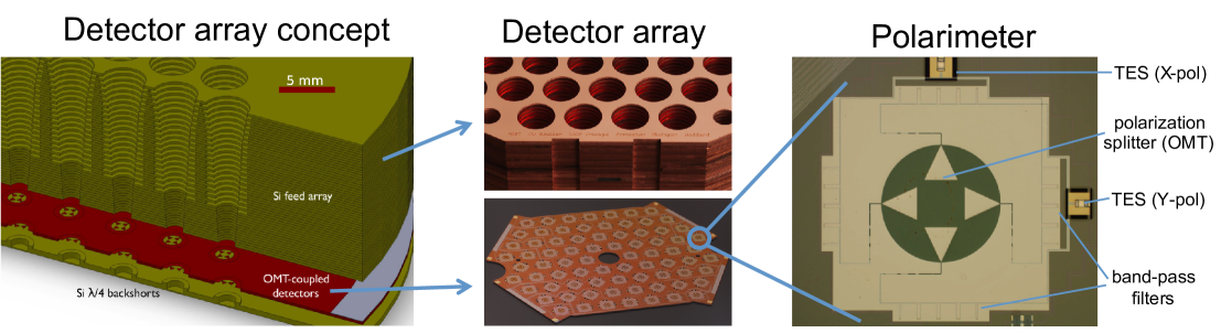
The multi-chroic arrays under development are an extension of the single-frequency Truce detectors 16. (See Figure 1) The optical beam is defined by a corrugated feedhorn, which has a long history of use in polarimeters in radio astronomy and CMB observations. Corrugated horns offer low sidelobes, circularly symmetric beams and a low cross-polarization over a wide bandwidth — ideal characteristics for use in polarimetry. The waveguide output of the horn couples to a planar ortho-mode transducer (OMT) 17 which separates the orthogonal polarization components of the incoming radiation into independent co-planar waveguides (CPW). The OMT defines a polarization axis that is independent of frequency. Each CPW transitions to a microstrip (MS) transmission line using a numerically optimized stepped impedance transformer. The signals then pass through a set of resonant MS stub filters which define the spectral pass-band of the detectors.
Once filtered, the incident power for each polarization is dissipated on a suspended and thermally isolated silicon nitride (Si3N4) island using lossy gold MS terminations, and the corresponding temperature change of this ‘bolometer island’ is detected by a MoCu transition edge sensor (TES). Summing the outputs of the two bolometers yields the temperature of the incoming radiation, and differencing the two yields the Stokes Q parameter. The full linear polarization state of a given location on the sky can be measured by combining measurements of multiple polarimeters rotated relative to each other, or by observing the sky at multiple parallactic angles.
With a few changes these detectors can be extended to octave (1:2) bandwidth. Octave bandwidth is sufficient to allow simultaneous operation at both the 90 and the 150 GHz frequency bands which lie on either side of the polarization foreground minimum, making these the most sensitive frequencies for CMB polarization studies.
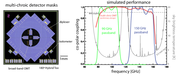
Figure 2 shows the detector layout for a multi-chroic 90/150 GHz pixel using a broader-band OMT based on Knchel and Mayer (1990)18. The four OMT fins feed diplexers that split the 90 GHz and 150 GHz bands into separate MS lines. These diplexers are based on the resonant stub filters that are used in the single frequency detectors which have consistently matched simulations at the percent level. The outputs of the diplexers from opposing arms of the OMT are fed into the inputs of hybrid tee designed following 19, one for each frequency band and polarization state. This tee combines the signals from the two lines to produce a sum and a difference output, with the sum output terminated and the difference output routed to a bolometer island for detection. The hybrid tee is important because circular waveguide is multi-moded over octave bandwidth. The desired TE-11 mode couples to opposite probes with a relative phase shift (selected by the difference output of the hybrid tee), while all other modes over this bandwidth which couple to the probes are in phase (and thus terminated at the sum output). Simulations show the hybrid rejects 99.9% of the unwanted modes with transmission of the desired TE-11 mode. This establishes single mode performance over the full bandwidth (1:2.2), which is crucial to maintaining excellent polarization performance in this system. In total, four bolometers are used to detect both linear polarizations in the two bands.
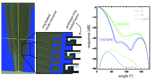
While standard corrugated horns do not offer sufficient bandwidth for these multi-chroic detectors, designs incorporating ring-loaded slots have demonstrated excellent performance for such applications 20, 21. Figure 3 shows the design and simulations for such a horn. It achieves input reflection below 1% and produces symmetric beams with peak cross-polarization below -30 dB over the entire band, from 80 to 160 GHz. This design is similar to a standard corrugated feed, but with the addition of ring-shaped cavities for the first 5 grooves. Prototype ring loaded layers have been fabricated using the NIST deep ion etch process 23 with depths controlled to micron accuracy, comparable to the tolerance of the standard electroforming technique. This silicon platelet array technology may prove to be the most economical method for producing large arrays of ring-loaded horns which are otherwise difficult to manufacture at mm-wave frequencies.
All detector components have been fully characterized using the same simulation tools (HFSS: www.ansoft.com and Sonnet: www.sonnetsoftware.com) used and extensively validated in the single frequency development. These simulations combined with estimates for dielectric losses predict an optical coupling efficiency of , polarization leakage below 1% and excellent cross-polarization from the corrugated horn.
3 Multi-Chroic Detectors on ACTPol
As originally proposed, the ACTPol receiver was designed to use three single-frequency lens-fed arrays of 512 polarimeters (see Niemack et al 2010 22). Each array is mounted in an ‘optics tube’ which contains of a set of three silicon lenses that re-image light from the telescope onto the cryogenic detector array; a cold Lyot stop to control illumination of the primary mirror; and filters to block infrared radiation. The detectors are read out by time-domain multiplexing (TDM) electronics provided by NIST 24, and are controlled by room temperature Multi-Channel Electronics 25, the same readout and control system used for ACT. The ACTPol schedule is to deploy a 150 GHz array in early 2012 followed by a second 150 GHz array and a third array in 2013. We plan to deploy a third array consisting of 90/150 GHz multi-chroic detectors instead of the originally planned 220 GHz array.
The sensitivity of a single detector improves as the horn aperture grows larger. For an array fabricated on a fixed diameter wafer (6′′ silicon in this case), as the horn size grows larger, the number of detectors decreases. This leads to a particular number of horns (and horn size) that maximizes the array sensitivity. Detailed calculations were performed, including a model of the telescope and atmospheric loading, consideration of bandwidth, and conservative estimates for the optical coupling. This calculation, subject to the constraint of using the existing 1024 channel readout, revealed that 256 detectors was the optimal choice. With this choice the array sensitivity is equivalent to an optimal 90 GHz array and 70% of a 150 GHz-only array. This provides a significant boost in sensitivity compared with the originally planned 220 GHz array. We note that the total array sensitivity could be further increased if we were not subjected to the constraint of using the existing readout.
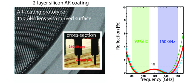
The input to this array must pass through a set of silicon lenses. We are developing a novel anti-reflective (AR) coating for the silicon lenses. This ‘coating’ consists of a two layer simulated dielectric layers constructed by removing grooves in two directions using a dicing saw to leave stepped pyramids on the lens surface. Figure 4 shows a prototype of this coating on a curved surface and its simulated bandwidth. This design offers extremely low loss and reduces reflections from each silicon surface below 1% across a bandwidth of 1:2, which is sufficient for these multi-chroic pixels. Metrology of the fabricated geometry show micron deviations from the design, within the required tolerance.
4 Conclusions
We have described our plans for extending the Truce single frequency horn coupled TES polarimeters to achieve multi-chroic performance. We will initially develop detectors with sensitivity in the 90 and 150 GHz bands where CMB polarization foregrounds are lowest. In the future, this architecture will be scaled to higher and lower frequencies to pursue a variety of science goals. This approach retains the advantages of horn coupled polarimeters including symmetric beams, low cross-polarization, and frequency independent detector polarization angles while enhancing sensitivity and frequency coverage. We plan to deploy an array of these detectors as part of the ACTPol project in 2013. This will serve as a technology demonstration and enhance ACTPol’s sensitivity to CMB polarization and gravitational lensing.
Acknowledgements.
We would like to thank the members of the Truce collaboration for their many contributions to this architecture.References
- 1 C. L. Reichardt, et al. ApJ, 694:1200–1219, April 2009.
- 2 J. Fowler et al. 2010.
- 3 Sudeep Das et al. Astrophys. J., 729:62, 2011.
- 4 H. C. Chiang, et al.. ArXiv e-prints, June 2009.
- 5 F. Piacentini,et al. ApJ, 647:833–839, August 2006.
- 6 T. E. Montroy,et al. ApJ, 647:813–822, August 2006.
- 7 C. Bischoff, et al.. ApJ, 684:771–789, September 2008.
- 8 J. L. Sievers, et al. ApJ, 660:976–987, May 2007.
- 9 E. M. Leitch, et al. ApJ, 624:10–20, May 2005.
- 10 Jiun-Huei P. Wu et al. ApJ, 665:55–66, 2007.
- 11 M. L. Brown,et al. ArXiv e-prints, June 2009.
- 12 C. Bischoff, et al. ArXiv e-prints, December 2010.
- 13 M. Lueker et al. 2009.
- 14 R. Keisler et al. 2011.
- 15 M. R. Nolta, et al. ApJs, 180:296–305, February 2009.
- 16 K. W. Yoon, et al. In B. Young, B. Cabrera, & A. Miller, editor, American Institute of Physics Conference Series, volume 1185 of American Institute of Physics Conference Series, pages 515–518, December 2009.
- 17 J. McMahon, et al. In B. Young, B. Cabrera, & A. Miller, editor, American Institute of Physics Conference Series, volume 1185 of American Institute of Physics Conference Series, pages 490–493, December 2009.
- 18 R. Kn chel and B. Mayer. In IEEE MTT-S International Microwave Symposium Digest, Dallas, pages 471–474, 1990.
- 19 P. K. Grimes, O. G. King, G. Yassin, and M. E. Jones. In Electronics Letters, Vol 43, Issue 21, pages 1146-1147, 2007.
- 20 Y. Takeichi and F. Takeda. In Microwave Symposium Digest, GMTT International, Volume 71, Issue 1, pages 36–37, May 1971.
- 21 Fenn Srikanth, Ruff. EVLA Memo 95, 2005.
- 22 M. Niemack et al. SPIE Conference Series, volume 7741, july 2010.
- 23 J. Bhardwaj and H. Ashraf. SPIE Conference Series, volume 2639, pages 224–233, September 1995.
- 24 P. A. J. de Korte, et al. Review of Scientific Instruments, 74:3807–3815, August 2003.
- 25 E. S. Battistelli,et al. Journal of Low Temperature Physics, 151:908–914, May 2008.