Quantum percolation in quantum spin Hall antidot systems
Abstract
We study the influences of antidot-induced bound states on transport properties of two-dimensional quantum spin Hall insulators. The bound states are found able to induce quantum percolation in the originally insulating bulk. At some critical antidot densities, the quantum spin Hall phase can be completely destroyed due to the maximum quantum percolation. For systems with periodic boundaries, the maximum quantum percolation between the bound states creates intermediate extended states in the bulk which is originally gapped and insulating. The antidot induced bound states plays the same role as the magnetic field in the quantum Hall effect, both makes electrons go into cyclotron motions. We also draw an analogy between the quantum percolation phenomena in this system and that in the network models of quantum Hall effect.
pacs:
73.23.-b, 73.20.Jc, 73.43.-fQuantum spin Hall (QSH) insulators have been known as two-dimensional (2D) topological insulators, which have been studied intensively because of the novel physics they host.Kane_RMP ; Zhang_RMP ; Moore_review The bulk of these systems shows insulating gaps but the system boundaries processes time-reversal symmetry (TRS) protected gapless surface or edge modes, characterized by the topological invariant. KaneMele_05PRL_1 ; KaneMele_05PRL_2 ; BHZ ; HgTe_experiment_1 ; Konig_JPSJ ; HgTe_experiment_2 Disorders are believed not able to cause backscattering of these modes because of their spin-momentum locking. In two dimension, these gapless modes are also known as helical edge states that are responsible for the QSH effectKaneMele_05PRL_1 ; KaneMele_05PRL_2 ; BHZ . In our previous works, we have shown that defects in the form of vacancies in 2D topological insulators can induce bound states that appear within the bulk band gap Shan_defect_BS ; Lu_impurity_BS . Electrons are able to go into cyclotron motions around the vacancies through these bound states, which is caused by the non-trivial underlying topology of the system. In reality, defects inevitably exist in 2D QSH systems. It is however not particularly clear how these bound states affect the QSH phase as well as the transport properties of the helical edge states.
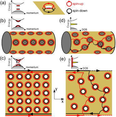
In this paper, we study QSH systems in which vacancies appear as arrays using theoretical models. Such kind of man-made systems have been referred to as antidot arrays.FGK_prl ; Weiss_prl In the well-studied 2D electron systems such as GaAs/GaAs based and InAs based heterojunctions, antidot arrays display intriguing physical properties.Bird_book QSH insulators are ideal platforms for studying antidot systems since they are true 2D materials with exotic physical properties. By defining antidot lattices on the 2D QSH systems, we show that antidots induce extra energy bands which can greatly smear the band gap. When exceeding the critical antidot density, the QSH phase can be completely destroyed. When antidots are randomly distributed, the existence of antidot-induced energy bands and band gap smearing is confirmed by calculating the density of states of the 2D system. We also study the transport properties in these systems under different boundary conditions. It is found that quantum percolation occurs taking the bound states as stepping stones. Physically this happens because of the finite spatial distribution and overlapping of these bound states. In the open boundary condition (OBC), the bound states formed transverse percolation channels allow the backscattering between conducting channels at opposite edges of the sample with the same spin, which then destroys the QSH phase (see Fig. 1e). In the closed boundary condition (CBC), the longitudinal percolation forms new conducting channels between the source and drain in a two-terminal configuration, as illustrated in Fig. 1d, which can be viewed as truly extended states. We found that transition from QSH phase to conventional insulating phase accompanies appearance of these extended states.
Following our previous worksShan_defect_BS ; Lu_impurity_BS , a modified Dirac model is used to describe the 2D QSH insulatorsshen-dirac ,
| (1) |
where is the quadratic correction to the topological mass term , () is the momentum operator. , and have the dimension of speed, mass and reciprocal mass, respectively. The Dirac matrices satisfy the anti-commutation relations (), and . A common representation of the Dirac matrices can be expressed as,
| (2) |
where are the Pauli matrices, is the unit matrix, and represents the Kronecker product. The Hamiltonian (1) preserves time-reversal symmetry , where is the time-reversal operator and is the complex conjugate operator. The topological nature of this Hamiltonian has been discussed in detail in our previous worksshen-dirac . This system is topologically non-trivial (with ) while , and trivial (with )while .KaneMele_05PRL_1
After appropriately reordering the basis, the Hamiltonian (1) can be decoupled into two blocksShan_defect_BS ; Lu_impurity_BS ,
| (3) |
with being the time-reversal counterpart of . Because the system keeps TRS, we only consider the block. When being discretized onto an square-lattice, the tight-binding version of reads,
| (4) | |||||
where is the annihilation operator of electrons at site with up spins but belonging to two different bandsBHZ , is the unit vector displacement (with length ) between two nearest-neighbor sites in the direction, and the on-site energy and hopping matrices in directions reads,
| (5) |
Numerically, the antidot is modeled by leaving the antidot regions as vacancies on the tight binding lattice. The CBC geometry is realized by adopting periodic boundary condition in the direction (see Fig. 1). Transport features are investigated through the combination of the non-equilibrium Green’s functionDatta1 and the Landauer-BttikerLB_formula formalism. During the calculation, the effects of each semi-infinite leads are taken into account by introducing the corresponding self-energy terms. To clearly illustrate the physics, we adopt such model parameters to describe the clean substrate: , , and , which is in the topologically non-trivial regime, i.e., . In the tight binding calculations, the lattice constant is set to be .
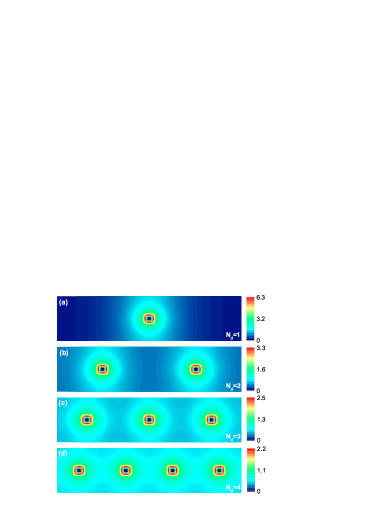
For antidots on a finite size sample, its induced bound state can be identified by directly diagonalizing the total tight-binding Hamiltonian. The bound states are states that have spatially localized wave functions and discrete energy spectrum. The antidot-induced bound states in 2D topological insulators are found both in the bulk band and in the band gap with wave function confined around it (Fig. 2a)Shan_defect_BS ; Lu_impurity_BS . However, those with energies existing in the bulk band gap are of most interest to us since they coexist with helical edge states in the QSH insulator. As an illustration, we plot out the in-gap bound state wave function for a single antidot and a simple antidot array in Fig.2. As is shown, the bound states are indeed localized around the antidots. Away from the center their wave functions quickly decay, which can be approximated in the form . Shan_defect_BS ; Lu_impurity_BS ; shen-dirac The characteristic decay length in Fig.2 in theory is about 11a, which agrees well with our numerical results. For the antidot arrays, as is seen in Fig.2, the in-gap bound states they induce overlap with each other and eventually become connected.
Consider an antidot array with 100-sites in width. The finite-size effect-induced energy gap in the clean system of this size is around ,ZhouBin_PRL_2008 , which is negligible compared with the bulk gap (). The antidots are equally spaced in both and directions with the spacing being sites. We calculate the spectrum of the antidot lattice with under both open and closed boundary conditions. Meanwhile the wave function of the lowest conduction band at (red solid circles in Fig. 3) is taken as an example to demonstrate the emergence of the intermediate states formed by the bound states in the band gap (Fig. 3 insets).
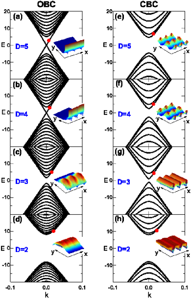
As the antidots become dense, the bulk band gap is found to close up and then re-opens, as is shown in Fig. 3. When and 4, the edge states survive under OBC. Meanwhile the antidot-induced energy bands already appear between where the bulk band gap was, as is seen in the lowest conduction band wave functions in CBC in the inset of Fig.3e. When gradually decreases, the band gap shrinks more. At the edge states in OBC disappear and the band gap is no longer non-trivial (Fig. 3c). In this case, the lowest conduction band becomes a bulk mode, as shown in the inset of Fig. 3(c). Since the antidot size cannot be continuously changed on the lattice model, this implies that there exists a critical point between and where the band gap vanishes and the QSH phase is destroyed. As the antidots become denser, the band gap further opens up and no states can be found in the low energy regime.
After consider the physical picture illustrated in Fig.2, it can be inferred that there is a critical point where the maximum percolation caused by the antidot-induced bound states exists. This can be explicitly demonstrated by calculating the two-terminal transmission coefficient with antidots randomly distributed in the sample. We choose a 2D sample composed by sites. sized antidots are randomly patterned at a density , which is defined as the number of antidot sites divided by . For example, in the antidot array case of Fig.3c and Fig.3g, the antidot density is . The Fermi level is fixed at but carefully avoided from the tiny gap from finite-size effect. The versus curves under OBC and CBC are shown in Fig. 4(a) and (b), respectively. For each , the sample averaging is taken with 100 random antidot configurations. Indeed, when is small, remains one/zero under open/closed boundary condition. But when approaches a critical value , under OBC drops dramatically while under CBC acquires a sharp peak with the peak value approaching 1, which is a signature of maximum percolation in the bulk. When , vanishes under both boundary conditions. The critical point value we find agrees very well with that we inferred from the previous results from the antidot arrays in Fig.3. And thus the physical picture of bound state induced percolation can be confirmed.
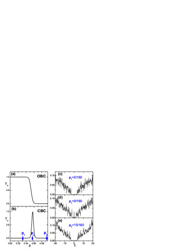
The above picture is further confirmed by calculating the system’s density of states. To eliminate the contribution of the edge states in the bulk band gap, CBC in both and directions are adopted. We choose three typical antidot densities: , and . For each density, the averaged density of states is calculated with 100 random antidot configurations using the kernel polynomial methodKPM . When , the original inverted bulk gap is reduced but still survives to protect the QSH phase, as is shown in Fig. 4(c). For , a sharp peak appears at as is shown in Fig. 4(d), which is from the conducting channel in the bulk formed by the in-gap bound state. The gap seen between the conduction and valence band in Fig. 4(d) is solely due to the finite size effect, because it can be inferred from Fig. 3(g) that in the continuum limit both the valence and conduction band spectrum should become continuous. When , the band gap re-opens and the system becomes a conventional insulator [Fig. 4(e)].
It is well established in the quantum Hall effect that the quantum percolation process is responsible for the transition between the quantized Hall conductance plateausran_network_model ; XiongGang_PRL , which is a direct manifestation of the localization-delocalization quantum phase transition. In the quantum Hall effect, electrons go into cyclotron motions because of the high perpendicular magnetic field in which process the disorders help to pin the cyclotron orbitals locally. The quantum percolation can thus be intuitively understood in the sense that the cyclotron orbitals connect with each other at some critical external conditions (e.g.: magnetic field strength, Fermi surface, etc). Based on this physical picture, the Chalker-Coddington network(CCN) model is developed which gracefully describes the localization-delocalization transition in the quantum Hall effect in the presence of disordersran_network_model ; CCN_model . Upon each of such transition, it is also accompanied by the change of the topological order of the system, namely the Thouless-Kohmoto-Nightingale-Nijs integerTKNN , which changes by 1 at each of these transitions.
In the QSH insulator we studied, the maximum percolation accompanied with destroying of the QSH phase can also be seen as such kind of localization-delocalization quantum phase transition. But in this case, it is accompanied by the change in the topological invariant from 1 to 0.Onoda_prl ; TAI Through our previous papers, it is made clear that the bound states themselves have helical nature (or chiral when considering only or sub-block)Shan_defect_BS ; Lu_impurity_BS , which is similar to the chiral nature of cyclotron orbitals in the quantum Hall effect. By analogy it is possible that at the critical antidot density, the bound states connect and form 2D networks in real space, i.e. the formation of percolation. At this condition, truly extended states exist and the localization length of electrons should diverge. The percolation provides new conducting channels in the bulk, which allows edge states be scattered backward across the sample through the other edge in OBC [as is seen in the drop of in Fig. 4(a)]. Meanwhile, the existence of extended states is proven by the dramatic raise of shown in Fig. 4(b). It is noted that in the QSH insulator, there are always two copies of percolation channels with opposite chirality, one from and the other from .
To conclude, our results indicate that appropriate density of antidots in a 2D QSH insulators can dramatically change the sample’s electronic structure and consequently the transport features. There exists a critical antidot density at which the bulk electrons becomes truly delocalized because of the quantum percolation channels across the sample formed by the antidot induced bound states. This localization-delocalization transition is accompanied by the vanishing of the QSH phase.
This work was supported by the Research Grant Council of Hong Kong under Grant No. HKU7051/11P, and by National Natural Science Foundation of China (Grant No. 11104060).
References
- (1) M. Z. Hasan and C. L. Kane, Rev. Mod. Phys. 82, 3045 (2010).
- (2) Xiao-Liang Qi and Shou-Cheng Zhang, Rev. Mod. Phys. 83, 1057 (2011).
- (3) M. Z. Hasan and J. E. Moore, Annu. Rev. Condens.Matter Phys.2 , 55 (2011).
- (4) C. L. Kane and E. J. Mele, Phys. Rev. Lett. 95, 146802 (2005).
- (5) C. L. Kane and E. J. Mele, Phys. Rev. Lett. 95, 226801 (2005).
- (6) B. A. Bernevig, T. L. Hughes, and S. C. Zhang, Science 314, 1757 (2006).
- (7) M. Knig, S. Wiedmann, C. Brune, A. Roth, H. Buhmann, L. W. Molenkamp, X. L. Qi, and S. C. Zhang, Science 318, 766 (2007).
- (8) M. Knig, H. Buhmann, L. W. Molenkamp, T. Hughes, C. X. Liu, X. L. Qi, and S. C. Zhang, J. Phys. Soc. Jpn. 77, 031007 (2008).
- (9) A. Roth, C. Brune, H. Buhmann, L. W. Molenkamp, J. Maciejko, X. L. Qi, and S. C. Zhang, Science 325, 294 (2009).
- (10) W. Y. Shan, J. Lu, H. Z. Lu, and S. Q. Shen, Phys. Rev. B 84, 035307 (2011).
- (11) J. Lu, W. Y. Shan, H. Z. Lu, and S. Q. Shen, New J. Phys. 13, 103016 (2011).
- (12) R. Fleischmann, T. Geisel, and R. Ketzmerick , Phys. Rev. Lett. 68, 1367 (1992) .
- (13) D. Weiss, K. Richter, A. Menschig, R. Bergmann, H. Schweizer, K. von Klitzing, and G. Weimann ,Phys. Rev. Lett. 70, 4118(1993).
- (14) Jonathan P. Bird, Electron Transport in Quantum Dots. Kluwer Academic Publishers (2003).
- (15) S. Q. Shen, W. Y. Shan, and H. Z. Lu, Spin 1, 33 (2011).
- (16) B. Zhou, H. Z. Lu, R. L. Chu, S. Q. Shen, and Q. Niu, Phys. Rev. Lett. 101, 246807 (2008).
- (17) S. Datta, Electronic Transport in Mesoscopic Systems (Cambridge University Press, 1995).
- (18) M. Bttiker, Phys. Rev. Lett. 57, 1761 (1986).
- (19) B. Kramer, T. Ohtsuki, and S. Kettenmann, Physics Report 417, 211 (2005).
- (20) G. Xiong, S. D. Wang, Q. Niu, D. C. Tian, and X. R. Wang, Phys. Rev. Lett. 87, 216802 (2001).
- (21) J. T. Chalker and P. D. Coddington, J. Phys. C 21, 2665 (1988).
- (22) A. Weie, G. Wellein, A. Alvermann, and H. Fehske, Rev. Mod. Phys. 78, 275 (2006).
- (23) D. J. Thouless, M. Kohmoto, M. P. Nightingale, M. Nijs. Phys. Rev. Lett. 49, 405 (1982).
- (24) Masaru Onoda, Yshai Avishai, and Naoto Nagaosa, Phys. Rev. Lett. 98, 076802 (2007).
- (25) Jian Li, Rui-Lin Chu, J. K. Jain, and Shun-Qing Shen, Phys. Rev. Lett. 102, 136806 (2009).