Mechanical properties of polycrystalline graphene based on a realistic atomistic model
Abstract
Graphene can at present be grown at large quantities only by the chemical vapor deposition method, which produces polycrystalline samples. Here, we describe a method for constructing realistic polycrystalline graphene samples for atomistic simulations, and apply it for studying their mechanical properties. We show that cracks initiate at points where grain boundaries meet and then propagate through grains predominantly in zigzag or armchair directions, in agreement with recent experimental work. Contrary to earlier theoretical predictions, we observe normally distributed intrinsic strength (% of that of the mono-crystalline graphene) and failure strain which do not depend on the misorientation angles between the grains. Extrapolating for grain sizes above 15 nm results in a failure strain of and a Young’s modulus of GPa. The decreased strength can be adequately explained with a conventional continuum model when the grain boundary meeting points are identified as Griffith cracks.
Grain boundaries define the electronic and mechanical properties of polycrystalline materials. Since chemical vapor deposition (CVD) is currently the only way for producing industry-scale graphene membranes, and leads to polycrystalline samples, study of grain boundaries in graphene has become of fundamental importance during the recent years. In a two-dimensional material, such as graphene, the boundaries also have a critical contribution to the chemical reactivity. Because of this, although atomic scale imaging can in principle reveal their exact structure, the boundaries tend to be covered by adsorbates with only short segments available for direct imaging. Nevertheless, experiments Cervenka2009a ; Huang2011 ; An2011 ; Kim2011 ; Kurasch2012 ; Tapaszto2012 have revealed meandering serpent-like boundaries which are typically formed from pentagon-heptagon–pairs in the parts not covered by the adsorbates.
Mechanical properties of graphene sheets have been a topic of intense research already for two decades in the context of carbon nanotubes (see Ref. Yakobson2001 for a topical review). More recently, in 2007 Liu2007 , Liu and co-workers utilized ab initio calculations to study the elastic moduli and fracture characteristic of graphene. Young’s modulus was found to be 1.05 TPa, and failure strain, depending on the pulling direction, 0.194–0.266. Intrinsic strength was estimated to be 110–121 GPa, similarly depending on the pulling direction. The role of pre-existing defects on these properties was also studied Khare2007 . It was noticed that their effect does not depend on the exact atomic structure of the defects but rather on their size. The authors also showed that the intrinsic strength of graphene with crack-like defects can be described with a continuum model using the Griffith formula for defect sizes down to 10 Å. Soon after this, Frank et al. used a tip of an atomic force microscope to obtain a Young’s modulus of 0.5 TPa for suspended stacks of graphene sheets Frank2007 . A year later, Lee and co-workers reported on several mechanical properties of graphene using a similar technique Lee2008 , establishing graphene as the strongest material ever measured. They reported an intrinsic strength of 42 N/m (corresponding to 130 GPa assuming graphene thickness to be the inter-layer distance in graphite, i.e., 0.335 nm) occurring at 0.25 strain. Young’s modulus was estimated to be 1 TPa, in a good agreement with theory Liu2007 . In 2009, Xiao and others reported on their theoretical work Xiao2009 , in which they obtained failure strain of ca. 0.10 for graphene sheets with Stone-Wales defects (one rotated bond) with an intrinsic strength very close to that of the pristine structure (the difference was larger for small-diameter nanotubes). This result would be consistent with the continuum model Khare2007 assuming the defect corresponds to a crack with a size below 5 Å, which seems reasonable for this defect.
These early works concentrated on either mechanically exfoliated pristine graphene or mono-crystalline graphene with point defects. The first experimental studies on mechanical properties of polycrystalline graphene samples were carried out only last year (2011) Huang2011 ; Ruiz-Vargas2011 ; Kim2011a . The experimental results can be summarized as follows: The intrinsic strength for polycrystalline samples is somewhat above one third of that for mono-crystalline graphene (ca. 35 GPa) Huang2011 ; Ruiz-Vargas2011 and cracks propagate through the bulk of the grains Kim2011a mostly along zigzag and armchair directions, not along grain boundaries as could be intuitively expected.
In the meanwhile, also theoretical work on energetics and other non-elastic properties Malola2010 ; Yazyev2010 ; Carlsson2011 ; Kurasch2012 of grain boundaries as well as on their mechanical response Grantab2010 ; Ruiz-Vargas2011 has been carried out. Total energy calculations Yazyev2010 ; Carlsson2011 have established that the idealized low-energy configuration of grain boundaries is a linear tilt boundary consisting of a repeating set of pentagon-heptagon–pairs which act as dislocation cores in a lattice otherwise constructed of hexagonal carbon rings. Intrinsic strength of graphene sheets with infinitely long such boundaries has been estimated to be 50–100 GPa with failure strains in the range of 0.07–0.15 Grantab2010 , depending on the misorientation angle between the adjacent grains. Since a higher misorientation angle yields a higher density of dislocation cores at the linear tilt boundary, but also to higher intrinsic strength of the model structures, the authors noted that their results disagree with the fracture mechanics model, assuming the heptagons of the dislocation cores correspond to Griffith cracks, which would predict graphene sheets to become weaker with an increasing defect density. If the grain boundaries themselves are indeed the weakest point in the lattice, this can be argued to be a reasonable comparison since also Stone-Wales defect consists of pentagons and heptagons and it has been shown to weaken graphene Xiao2009 . However, despite similarities between the theoretical models Yazyev2010 ; Carlsson2011 and short segments of the actually observed non-decorated boundaries Cervenka2009a ; Huang2011 ; An2011 ; Kim2011 ; Kurasch2012 , it remains unclear whether such infinitely long linear arrangements of dislocation cores can serve as a realistic model for studying mechanical properties of polycrystalline graphene.
Theoretical calculations presented along the experimental work in Ref. Ruiz-Vargas2011 assumed that voids would exist in polycrystalline graphene samples and that they could explain the apparent discrepancy between the experimental results of GPa and the theoretical estimates of 50–100 GPa. However, it is questionable how well this model corresponds to actual polycrystalline graphene samples. Moreover, the inherent difficulties in assessing the mechanical properties of a membrane suspended on a hole by applying force with a tip of a microscope necessitate theoretical confirmation with a realistic model system.
Here, we describe an automated method for creating polycrystalline graphene structures with realistic misorientation angle and carbon ring size statistics as well as serpent-like boundaries similar to those observed experimentally. Using atomistic simulations, we then subject our samples to a study of their mechanical properties. We show that close to the failure strain, cracks appear typically at the points where grain boundaries meet, and in agreement with the recent experimental studies, then propagate through grains predominantly in zigzag or armchair directions. Contrary to earlier theoretical predictions Grantab2010 , neither intrinsic strength nor failure strain of our samples depend on the misorientation angle between the grains, but are normally distributed similar to recent experimental studies, Huang2011 ; Ruiz-Vargas2011 where intrinsic strength of GPa was reported. We obtain a slightly higher value (46 GPa) which is still in a reasonably good agreement with the experimental one. At the large grain size limit ( nm) the failure strain is about 0.09 and Young’s modulus is close to 600 GPa. The formation of cracks at the meeting points of grain boundaries, completely neglected in the previous theoretical studies, resolves the discrepancy between the experiments and the theoretical results and shows that the Griffith model can after all be used to describe the mechanical properties of polycrystalline graphene samples when a realistic atomistic model is used.
Without pre-patterned seeds for growth, CVD growth of graphene is initiated at several nucleation sites simultaneously. On a substrate such as Cu, which doesn’t offer epitaxiality, the lattice orientations of the growing grains are random Yu2011 . To mimic such growth, we first wrote a computer code which creates a pre-selected number of randomly placed nucleation sites on a plane with pre-defined dimensions. For each such nucleation site () a random orientation is selected for the lattice. In order to obtain approximately uniform size distribution for the grains, the sites are required to be at least 5.0 Å apart from each other (5 Å was selected arbitrarily). Next, we carry out an iterative process in which any of the missing neighbors of the already inserted atoms can appear with the same probability. When two grains approach, we use the following condition for deciding whether a lattice site is available for another atom: if Å or ( is the distance between the lattice site and the closest existing atom, is the number of atoms created closer than Å to the present site, where is the length of the graphene lattice vector) the site is not free and will thus be disregarded for further growth. Upon testing, this condition was found to minimize the dangling bond density at the boundaries.
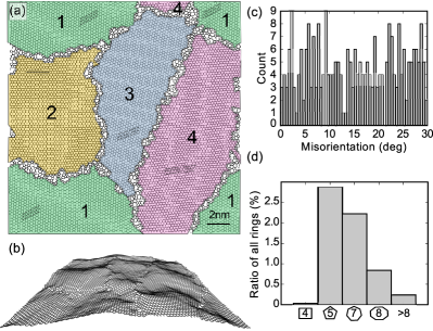
To equilibrate thus created polycrystalline samples, we first annealed them at 3000 K for 50 ps after which the system was quenched during a 10 ps run allowing the lattice to obtain its equilibrium size (pressure driven to zero). At this point the lattice appears somewhat crumpled even after pressure relaxation since we did not restrict relaxation in the out-of-plane direction. All simulations were carried out with the classical molecular dynamics (MD) code parcas Nordlund1995 ; Nordlund1998a ; Ghaly1999 with a reactive bond order potential developed by Brenner et al. Brenner2002 . Due to the large number of atoms in the structures (up to almost 10000) and large number of structures (385 in total), this is the only feasible method for carrying out the simulations. A similar simulation setup has been used in earlier theoretical studies of mechanical properties of graphene Grantab2010 , where a good agreement with ab initio methods has been noticed. Temperature and pressure control were handled using the Berendsen method Berendsen1984 . The equilibration procedure leads to grain boundary structures similar to the 20 nm 20 nm model presented in Fig. 1a,b.
After establishing a method for creating model structures for polycrystalline graphene, we applied it for creating 385 bicrystalline structures with grain sizes between –16 nm. Two randomly placed seeds were used for each structure to obtain exactly one misorientation angle () per structure. The resulting distribution of is presented in Fig. 1c, where if and otherwise (for graphene any ). As expected for two randomly selected orientations, the distribution is uniform with fluctuations resulting only from the finite sample size. In Fig. 1d, we plot the relative occurrence of carbon rings other than hexagons within the created structures. The combined likelihood for tetragons and pentagons is similar to that of heptagons and octagons indicating mostly saturated bonds at the boundaries. The significantly lower probability for rings with more than eight atoms is a sign of an existing but small local density deficit at the boundaries. Overall, the ring statistics seem reasonable. We noticed only very rarely if ever four-coordinated atoms which would indicate problems with the interaction model (such coordination is never observed in -bonded graphene even when it is heavily amorphized under an electron beam Kotakoski2011 ; Meyer2012 ). However, almost all structures contain a few under-coordinated atoms which could serve as reactive sites for covalently bonding adsorbates on the grain boundaries. Thus, the experimentally observed high coverage of grain boundaries gives further credibility for our model structures.
Next, we subjected the created sample structures to extensive tensile testing. The simulations were carried out at 300 K as follows: we applied uni-axial strain in a step-by-step fashion always equilibrating the structure for 5 ps before increasing the strain (much slower pulling was also tested with no apparent change in the results). We employed periodic boundary conditions for all simulations in the in-plane ( and ) directions. For this part of the simulations we modified the cutoff of the interaction model to remove the unphysical softening at longer inter-atomic distances (above Å), which is crucial for many MD simulations, but in the present case only affects at high strains by leading to nonphysical features in the stress-strain curve. For inter-atomic distances below Å, the interaction model remained unchanged. Modifying the cutoff has also before been noticed to be required for properly addressing the mechanical properties of graphene close to the fracture strain Grantab2010 . The continuity of atomic trajectories and conservation of energy were monitored during the simulations to avoid any problems resulting from this modification. We also carried out test simulations to check that the differences caused to the stress-strain curves – either in pristine graphene or our bicrystalline samples – were limited to the unphysical features near fracture.
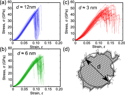
The stress during deformation was calculated from the Virial expression as explained in Ref. Grantab2010 assuming a thickness of 0.335 nm for the graphene membrane. The resulting stress-strain curves for grains with three different average sizes are presented in Fig. 2. For pristine graphene, our method yields an intrinsic strength of 90–100 GPa at a failure strain of 0.15–0.20, depending on the pulling angle, in a good agreement with the ab initio results Liu2007 . As can be seen in Fig. 2, the presence of grain boundaries leads to approximately a 50% reduction of the strength of the material independent of the grain size (intrinsic strength corresponds to the maximum stress before the failure). For grain sizes above nm, the average fracture strain is close to 0.10 (Fig. 2a), whereas for the smaller ones it increases gradually (see Figs. 2b,c) up to ca. 0.15 for the smallest reasonable grain sizes ( nm). This is because the grain boundaries are more flexible than the bulk of the grains, and their role is pronounced at small grain sizes allowing higher overall strains. We point out that the Poisson effect has not been taken into account in the presented data. However, we checked whether it would affect the results by carrying out a subset of the simulations also without periodic boundaries in the -direction. The observed deviations were within the uncertainties stemming from the finite sample size (that is, those seen in Fig. 2).
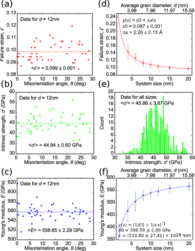
To better understand how the different measured properties depend on the grain size () and misorientation between the grains (), we plot in Fig. 3 the failure strain, intrinsic strength and Young’s modulus as functions of and . For the data plotted as a function of (Fig. 3 a-c), we used only one grain size ( nm) to ease the interpretation of the results. What can be readily observed is that none of the calculated properties depend on . Instead, they are normally distributed over an average value, in a stark contrast to the earlier theoretical prediction based on infinitely long linear grain boundary structures Grantab2010 . However, when the failure strain is plotted as a function of (Fig. 3d), a clear size-dependency emerges, as was qualitatively described above. For intrinsic strength (Fig. 3e) we observe no -dependency at all. Instead, the data is normally distributed for all around a value of GPa. While Young’s modulus is defined as the change in stress divided by the change in strain for the linear part of the stress-strain curve (Fig. 2), its -dependency is determined by that of the strain (Fig. 3f). For the strain, we can describe the different contributions of the bulk of the grain and the grain boundary with a constant describing the large-grain-size-limit and term inversely proportional to the grain size () to obtain . Fitting this equation to the data for the failure strain yields a very good agreement as can be seen in Fig. 3d. Through the fit we obtain failure strain for large grains of . A similar fit for the Young’s modulus (Fig. 3f) gives a value of GPa similarly for large grains.
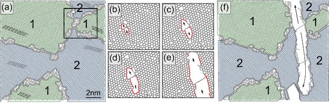
To further understand why the breaking stress is -independent, we visually analysed the evolution of the atomic structure of our samples upon fracture. An example is presented in Fig. 4. What we noticed is that the crack formation often occurs at the points where the grain boundaries meet (marked with a square in Fig. 4a). After the crack is formed, however, it propagates typically along the armchair or zigzag lattice directions in the bulk of the neighboring grains, similar to what has been recently suggested based on experimental observations Kim2011 . While the atomic structure of the boundaries, and that of their meeting points, are independent on the grain size, the fracture properties must also be grain size-independent, which is exactly what we observe in our results. Moreover, the characteristic size of these meeting points in our structures (as can be seen in Fig. 1a and Fig. 4a) is nm, which can be compared to the Griffith model data from Ref. Khare2007 . The data would indicate that such a crack size would result in roughly 50% reduction in the strength of the material, in agreement with our data.
As a conclusion, we established a method for creating realistic polycrystalline graphene samples for atomistic simulations. We applied this method for creating a representative set of samples for mechanical testing, and showed that the presence of grain boundaries reduces the strength of graphene by about 50% (down to GPa), in a reasonable agreement with experiments Huang2011 ; Ruiz-Vargas2011 . However, we observed no misorientation-dependency on any of the mechanical properties of the created samples which was recently suggested based on a theoretical study on graphene structures with infinitely long linear grain boundaries Grantab2010 . Furthermore, we showed that crack formation occurs at points at which the boundaries meet and that the cracks propagate through the bulk of the neighboring grains typically along armchair and zigzag directions, similar to recent experimental findings Kim2011 . The failure strain for polycrystalline graphene with grain sizes nm was found to be with a corresponding Young’s modulus of GPa. Overall our results show that the mechanical properties of polycrystalline graphene can be reasonably well described using the continuum model if the grain boundary meeting points are identified as the Griffith cracks in this material.
References
- (1) J. Červenka and C. F. J. Flipse, Phys. Rev. B 79, 195429 (2009).
- (2) P. Y. Huang et al., Nature 469, 389 (2011).
- (3) J. An et al., ACS Nano 5, 2433 (2011).
- (4) K. Kim, Z. Lee, W. Regan, C. Kisielowski, M. F. Crommie, and A. Zettl, ACS Nano 5, 2142 (2011).
- (5) S. Kurasch, J. Kotakoski, O. Lehtinen, V. Skakalova, J. Smet, C. E. Krill, A. V. Krasheninnikov, and U. Kaiser, under consideration (2012).
- (6) L. Tapaszto, P. Nemes-Incze, G. Dobrik, K. Jae Yoo, C. Hwang, and L. P. Biro, Appl. Phys. Lett. 100, 053114 (2012).
- (7) B. I. Yakobson and P. Avouris, in Carbon Nanotubes, Topics Appl. Phys., edited by M. S. Dresselhaus, G. Dresselhaus, and P. Avouris (Springer-Verlag, Berlin, Heidelberg, Germany, 2001), No. 80, pp. 287–327.
- (8) F. Liu, P. Ming, and J. Li, Phys. Rev. B 76, 064120 (2007).
- (9) R. Khare, S. L. Mielke, J. T. Paci, S. Zhang, R. Ballarini, G. C. Schatz, and T. Belytschko, Phys. Rev. B 75, 075412 (2007).
- (10) I. W. Frank, D. M. Tanenbaum, a. M. van der Zande, and P. L. McEuen, Journal of Vacuum Science & Technology B: Microelectronics and Nanometer Structures 25, 2558 (2007).
- (11) C. Lee, X. Wei, J. W. Kysar, and J. Hone, Science 321, 385 (2008).
- (12) J. Xiao, J. Staniszewski, and J. Gillespie Jr., Composite Structures 88, 602 (2009).
- (13) C. S. Ruiz-Vargas, H. L. Zhuang, P. Y. Huang, A. M. van der Zande, S. Garg, P. L. McEuen, D. A. Muller, R. G. Hennig, and J. Park, Nano letters 11, 2259 (2011).
- (14) K. Kim, V. I. Artyukhov, W. Regan, Y. Liu, M. F. Crommie, B. I. Yakobson, and A. Zettl, Nano letters 12, 293 (2012).
- (15) S. Malola, H. Häkkinen, and P. Koskinen, Phys. Rev. B 81, 165447 (2010).
- (16) O. V. Yazyev and S. G. Louie, Phys. Rev. B 81, 195420 (2010).
- (17) J. M. Carlsson, L. M. Ghiringhelli, and A. Fasolino, Phys. Rev. B 84, 165423 (2011).
- (18) R. Grantab, V. B. Shenoy, and R. S. Ruoff, Science 330, 946 (2010).
- (19) Q. Yu et al., Nature Mater. 10, 443 (2011).
- (20) K. Nordlund, J. Keinonen, and A. Kuronen, Physica Scripta T54, 34 (1995).
- (21) K. Nordlund, M. Ghaly, R. S. Averback, M. Caturla, T. Diaz de la Rubia, and J. Tarus, Phys. Rev. B 57, 7556 (1998).
- (22) M. Ghaly, K. Nordlund, and R. Averback, Phil. Mag. A 79, 795 (1999).
- (23) D. Brenner, O. Shenderova, J. Harrison, S. Stuart, B. Ni, and S. Sinnott, Journal of Physics: Condensed Matter 14, 783 (2002).
- (24) H. Berendsen, J. Postma, W. Van Gunsteren, A. DiNola, and J. Haak, J. Chem. Phys. 81, 3684 (1984).
- (25) J. Kotakoski, A. V. Krasheninnikov, U. Kaiser, and J. C. Meyer, Phys. Rev. Lett. 106, 105505 (2011).
- (26) J. C. Meyer, F. Eder, S. Kurasch, V. Skakalova, J. Kotakoski, H. J. Park, A. Chuvilin, G. Benner, A. V. Krasheninnikov, and U. Kaiser, Phys. Rev. Lett. in press (2012).